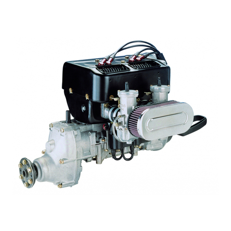
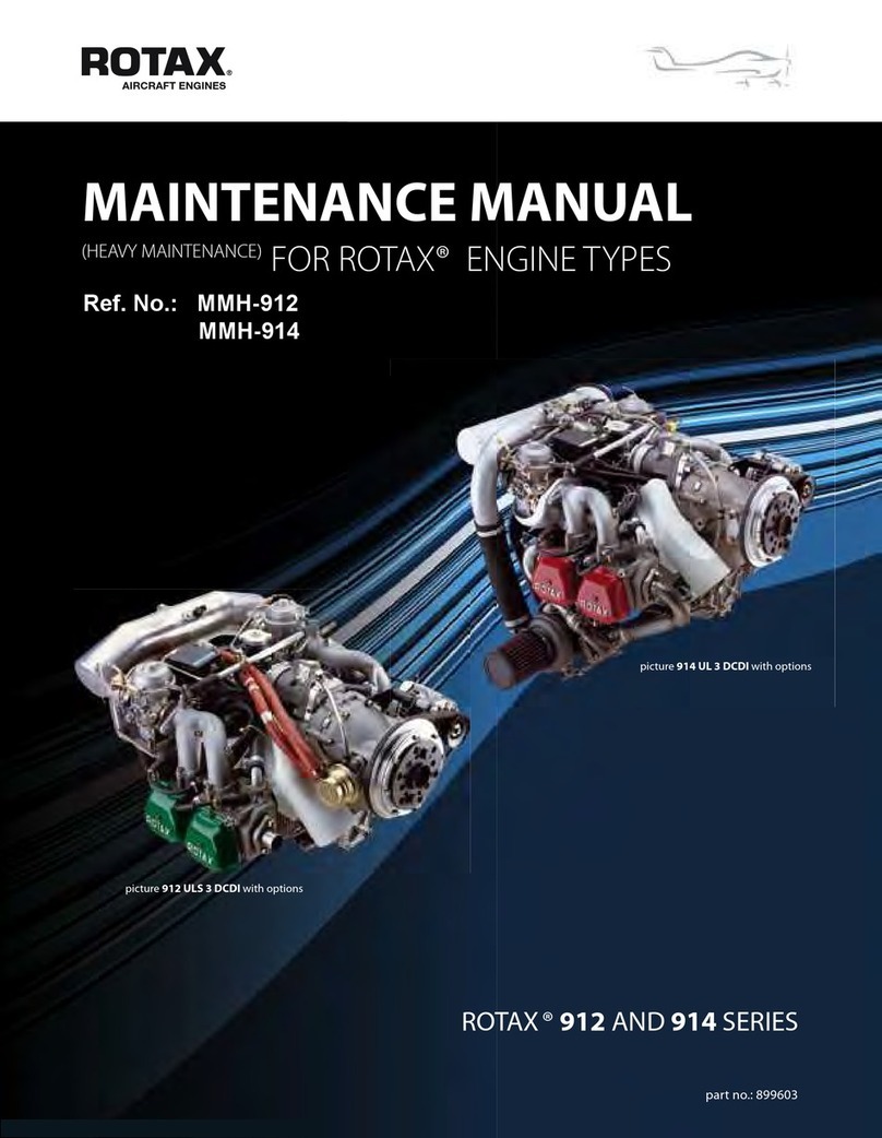
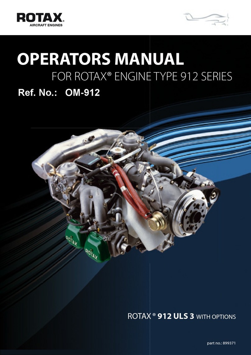
Rotax 503 UL User manual

ROTAX.
f
I
l
OFERATORIS
IWANUA-L
ENGINE TYPE
SosuL
equipped
with breakerless
dual ignition system
and BING carburetor
EDITION: 12
1990
This
manual
contains
i-po"t ffi
infolmation concerning
your engine.ft mustremain
with
the engine
at time of resale.
rl
I

Modifications
or spccial
applications
i
ri

Section
l. Importantprefacc,
genelalsafetypoints...............,..........
2. Forcword.......
3, Fuel&oi1.........................
Mixing
procedure.....
4, Sbrting
proccdurc,pre-st!-n
check
procedure
.................
5. Break-inDroccdure...................-.....
Index Page
5
6
6
7
8
9
ll

Danger!
Thisengine,byitsdesign,
issubjecttosuddenstoppage!
Engine
stoppage
canresult
incrash
landings.Suchcrashlandingscan
lead
toserious
bodily
injuryor death.
Neverfly theaircraft equipped
with thisengine
at locations,
airspeeds,
altitudes,
orother
circumstances
frorn
whichasuccessfulno-powerlanding
cannotbe
made,aftersudden
engine
stoppage.
Warning!
Although
these
enginetypes
have
undergoneconsiderabledurabilityte-
sting,thisengine
isnot a certifiedaircraftengine.Ithasnotreceived
any
individual safetyor durabilitytestingandconformstonoaircraftstan-
dards.
It isfor usein experimentalandultralightuncertifiedaircraftand
vehicles
only,
in whichanenginefailurewill notcompromise
safety.
Userassumes
allriskofuseandacknowledgesbyhisusethatheknows
this
engine
issubject
tosuddenstoppage.

.
I
1) Important
preface:
Safcty
i6everyone'sbusiness.Wehaveincludedsomeof theimportant
safetytipshere,
butthe
lisris
notcomplete.It wouldbe
impossible
tolist every
wayin whichonemaybeinjured. Please
notedre
followingsymbols
throughour$e book.
- S,A.FETY
WARNING: Failureto obeyasafety
warningmayresultin injury toyouorothers.
- INFORMATION vital to the operationor maintenance
of your product (this shouldalsobe
considercdnecossaryfor safety).
Generalsafety
points:
- Nevermixfuelin anenclosed
alea,orwherefumes
couldrcachanignitionpoinr.
- Makesureall enginecontrolsareoperative,thatyouknowonandoff positions
of throttle
andignition, thatthey areeasilyaccessible,andrhatyou canoperaletheminstinctively
withouthesitation.
- Nevcrrefu€l
iffuelcouldbespilled
on
hotenginecomponenrs.
Useonlysafery
applovedfuel
containe$and ever
Eansportfuel
inanunsafemanner.
- Checkengine
suspensionfaequentlyaswellas
fle driveconrponenrs,
fuellines,wirtlg,and
flrel arrdair fllters.
- Checkforfuelcontamination,airvents,
etc.
Prcte{tengine
whilenotin
useftornany
contami-
nationentering
fuel or cmburetion
systembut besureto rcmovestorageuotection befoe
startingengine.
- Maintain
yourengine
intopconditionandassumeit'sgoing
to
quitrunning
atanydme.I-eave
yourself
awry outin lheevent
of unexpectedfailure.
- Neverruntheeogineonthegrcund
withfte gopeller tuming,unless
youaredoingsoin a
runupareanndcarobserveanyoneorarythilg enteingthedutgerarea.An observerin asafe
place
isadefinite
asset.
- Neverleave
your
aircraftorothervehicleunattendedwhilctheengineisrunning.Ifoperated
by someoneelse
youcouldbesuedeven
if theuse
was
unauthorized
byyou.
- Keepanengine
1og
andenteranyunusualengine
behaviour.
Donotfly unless
you
have
corectedagivenproblem
andrccordedthecorrection
in thelog.
Lr)
'
^'
A
^.

I
2) Foreword:
TheROTAXengineisanair-cooledz-strokeengine,
Carefuland
extensivelytested
design
andrugged
consEuction
aswell astheuse
of highqualityparrs
increasoreliabiliry and
durabiliry,Wirh proper
maintenanceandcareandwiththeuseofsuitablefuelandoil dreengine
should
give
yougoodservice
for manyyears.
TheROTAX designincorporatesthelatesttechnical
developments.In
orderto tate advantage
of
futue developmentswercseNerhedghrromake
modificationsintheROTAX design
withoutnorice.
NOTE:All fasrenersaremetricwiththeexceptioooftheinternal
thread
ofthe
p.T.
O_cankshaftwhich
is1/2
"narionalfineftread.Itisto
your
advantage
to
read
thismanual
carefullyforthe
ptotection
ofyour
engine.Theremaybesigrficant
differencesfrom
othettypes
offwocycle
engines
you
mayhaveworkedon.
Alwaysuse
genuine
ROTAX pafis.
I A Neue.r,raenginewirhoutproperloading,
e.g.corect propeller.
Refersection17.
Section
3
Fuelandoil:
Fuelcoltamination
isa
najorcauseofenginefailure.The
bestplace
toavoidcontamination
is
atthe
source.Once
inyorufuel
container',averyharzadouspotendal
edsts.
Use
aclean
safety
approved
storage
corltainer.
Filter all fuelenteringandleavingthiscontainer.
Do
nol
over- conlainer.allowforexparrsion.
WARNING: Gasolineisflan]mableandexplosive
undercertain
conditions.Alwaysperform
pioce-
dDresin awellventilatedarea.
Donot
smokeorirllow
openflames
orspaJksin tie vicillity.
Neve'raddfuel while engineisnuudDg.
Refertoteclmicaldata-TheengineisdesigdedtooperateafuelfiitI.yJith
2Eaoil. Beswetouse
ploductsof atleastthestandardshownin thetechnicfll
datasectioD.
Ifthe
engioeistobeusedinverted
(with
spark
plugspointing
down)
selectalubricant
whichfeatures
lowcarbondeposits.Oilresidueteidsrodrain
to
lowpoints,
i.e.
spark
plug
cavities.
If rhisresidue
fails to burn cleanduring normad
operation,
plug tbuling will occur,possible
prc-ignirion also.
Manufacturersof suitablelubricanrswill guariurtee
theirproducts
in writing.
Do notusefuel whichhasbeenstorcdfor alongperiod
of time.
Do flotleavefuel exposedto sunlightin translucentcontaine$.
1)
A
3.1)Mixing procedure:
STEPno.1:
Useacleanapproved
container
ofknown
volume.Tohelp
predilute
tle oil,pour
a
bit of fuel intocontainer.
STEPno.2: I FiI k ro*r, urnoontof oil intocon-
tainer.
Oilmusr
beapprovedforaircooled
enginesat 50:1mi;cing
ratio.Agitate
slighdyto diluteoil with gasotine.
STEPno.
3:Addgasoline
toobtaindesired
mixture
ratio
(use
hne mesh
screen).
Fueimust
beofminimum
M.O.N.
83orR.O.N.
90octane
nting.
STEPro.4:
Replacecontainer
cap
and
shakerhe
con-
tainer
thoroughly.
Then
using
afunnel
withafinemesh
screen
toprevent
the
entry
ofwaterandforcignparticles,
trans-
fer mixturefrom containerinto thefuel
tank.
?
?
ffi
?
=
ffi

4) Startingprocedure:
4,1) Pre-startcheck:
Beforcstartingenginereadsectiondcaling
withstaning
and
cngine
htak-in thoroughly.The
servicelifeofthca[gine
islargelydeteminedbyhowwcllyou
followtheseinstsuctioqs.
Before
starting
enginebesure
your
installationiscomplet€,eosurethatallcontolsopffatc
easilyandsmootbly,and
that
you
caaoperatethem
instinctively.
Alwaysensuethat
you
areinasafc
run-upa!ea-
Ensurctluottlc
link.ge
allows
piston
valveincarbEetor
tobofiominidle
position,
Screwout
idle specdadjustmcntsclgw(no.14,
scction7) until carburcor
pistod(no.3)bottoms.
Carefullytum
inadjustment
scrcwuntilit engages
pisto[andtumh afudrer3to31/2full
tums.Checkif fuelline
isconrlertedardtankvetrtisoDen.
4,2)Procedure;
Oncoldengineapplychoke
fully.Ensureidle
position.(Opening
throtdewill gready
rcducc
chokeeffectlesultinginhard
stardng).
Make
sure
ignition
switchisonandthat
you
can
shut
itoffinstandyifnecessary,Pullstarterurtil firDllyengagsdandthen
pullthroughvigolously.
Above
plocedue
should
berepeateduntilenginebegins
to
firc.As
soonaselginestafis,shift
the
tbrotde
slowly
tolowspeedandrcmovechokeassoonas
possible(prolonged
useofchoke
can
causeenginetoflood,)
Ifthc engine
fails
tostart
oroperatesonlyononecylinder,chcckwhcthertheignition
wiring
isdisconnccted
orincore{dyconncctedto thespark
plug
connectorsorto th€
spark
plugs
or
theignitiol s]vitchisinoffposition.
If Feceding
checksdonotsolvethe
problem,
rcmovethespark
plugs
andinspecLwet
spart
plugs
indicateafloodedengine.
Tocorpct,replacewithdryplugs
anddiscontinueuseofchokc,Switchofrignition.Craok
engine
withfully opendrotdo toclcarthcexcess
fucl.
Repeatstan
proccdurc.
Dryspark
plugs
indicatcnofuelinonginc.Toinspect,reEovefloatbowl
and
cnsue
fuelis
present
in suficietlt
quantity,
If not,inspectfuellevelintank,fuelvalyeand
tank
ycnt,
I-ook
forblockage
orobstruction.
Corcat8ndrcpeatst{t proceduc,
A
I

Section 5
5) Break-in
procedure:
for aircraft installation (in otherapplications
prcceed
accoldingly)
Thobreak-inhas
tobepcrtbrmed
withdrccngineinstalled,
properlyloaded, i.e. propeuer
installed,
matched for max. r,p.m.In caseof anaircraft,anchorthcplaneto theground.Rutrtheengine
according
to thefollowing graph:
Engine
r.F.m,
H|000
,nta, fp.m.
(rcferpage
32)
20 50
sec sec l2 5
mlnmin min
t0
sec t5
sec
5,5
I
4,5
4
5,5
5
I
In.6
^'
.
^'
T
0 r0 20 30 40 s0 60 illHi
h caseof a
f&g3L!!g:i!c it ispossible
thatthe
coolingairflow onground
isnot cnoughtoprovide
thenecessarycoolingfor alongcrperiod.
Therefoleit is necassary
toobservecarcfullythe
cylinder
hggl temperaturc
(CHT) during breal in procedure
to avoidoverbearing.
Beforc exceeding
tie
maxiorumallowedCHT of 250
oC/ 480o
F intenupttherunandcooldownthcengine atidlc for
approximately
oneminuteand
continuewhere
youhaveintefiupted.
Be sureto usea saferun-rp area-to anchor
aircraft at those
points approved
by the airframe
manufacturer,andtohavesomeone
present
who
isabletoshut
off lheengineinstandy
andtoprcvent
unauthorizerl
people
entcring
the
duDger
area.
Proper
clorhing,ear
plotection etc, shouldbeusedonanyenginerun-uptest.
After thisprocedure
theidlehastobeadjusted.Thenshort
take-offs
canbeconducted.
After afew
short
full-load take-offs,but
notlaterthan2hourstotalrunning
rime,
thecylinderheadnuts
haveto
be
rc-torquedto22Nm(195
in.lb.). Forthis
procedurc
thecylindercowl(if any)hastobe
takenoff.
I r I r | | ll 2
Engine
mustbecoolfor re-torquingof head.

DiagramJor torquesequencewhen
manifold,sarcin
place s-q
n
,v,
/T\ /T\
3\-/ \r 5
.7
NOTE: Consider
bothcylindersasoneunitbecausetheyare
joinedbyexhaustandintakemanifolds.
Useacrosssequence
for tightening
the
nuts,
startingfiom thecenter.EnsurE
thalcowlscrcws
aretoroued
less
than
headnuts.
6) Operation
in flight:
It is rc{ommended
to usefull duottleduring uke-off climb. Slightthrctdereducion maycrcare
a
lealer mixtureaadmustbeavoided.Selectacruisingspeed
where
theengineis runningsmooth.
Donotexceed
rraximunengine
rpm(refer
section18technicaldata).
During cruiseanddescending
it is veryimponant
not tocreatealeanconditionwirhhighrym and
lowtluottleopedng.
Thglessfreshchargetheelgine
gets,
themorehotrcsidual
gas
rcmainsin the
cylinder.This
raisesdretemperaturestoacdticallevel. For this reason,
you
ncay
alsoexpedence
higherexhaust
gas
amdcylinderheadlempentures
atreduc€dthrottleopenings.
Idlingr.p.m.is2000minimum.Highidleseftingwill rcduceenrichment
actionof startingsystemin
carburcto!
(choke),
makingcoldstartingdifficult.
kior toshutdown,
engineshouldbe
runforafewminutes
atthelowestsmoothrunning
r.p.m.
tocool
down,depending
on
previous
power
selring.
Do|otidlgforFolonge.dpe
odsas
nomul chcondition
atthis
power
settingcancausg
u necessary
carbondeposits
and
spurk
plug
fouling.Avoidrunningconditions
whele
gearbox
shakingoccurs.

Section7
7) Carburetionr
7.1)
BINGCarburetor
- typicaldescription:
(Note:thisisnotapafislist)
B
a;\
n
tl
U
E
EI
n
ll16
E-<-1 III.9
1)
2)
3)
4)
5)
6)
7)
8)
ol
10)
11)
12)
r3)
14)
15)
16)
17)
18)
BING-doubleflo
atcarburetor
carburctor
hausing
carburetor
piston
jet needle
idlerjet
needle
jet
miring tube
mqitr
jet
sieve
sleeve
floatneedle
valve
float
Jloatchomber
atrscrew
adjustnErrt
screw
vefi ntbe
starting
piston
rtd pwtp asa. (rype
503singlecarb.)
fuelpuntp
assy.0!pe
503two
carb.)
.g -o{
%
:%
14
n
I to
EI
ti
€a
7
IA
0'o
@
\_l
tg 12

A
'
TheBING carburetor
isapistontypecarbuetorwi$ floatchamb€r.
Thecarburetor
canbeadjusted
by
jetreplacementofvaiious
approvedsizes,byadjustingidleair/fuelmixtulescrew,carb
piston
stoD
adjustment,
needle
sizes,andneedle
position.
In nocaseshould
jet changesbemadeby unqualifiedpeNons
or thosewhodonot haveROTAX
technical inforDation to doso.
Theairlfuelmixtur€atidlespeedisadjusted
bytheaaadjusting
screw
(see
ill. no.13).Theidler.p.m.
isadjustedbythe
carburetor
pistor
adjustment
screw
(ill.no.14).
NOTE- these
idle
adj[stm€nrsinreract,soadjusting
onemay
rcquir€minor
adjustment
oftheothe!.
NOTE - Onsingle
carb
enginesthecarburctorrnust
bein anexacrright angle
positiot in relation
to
thecrankshaftin bothviewsfromtopandfromtheintake
sidetoensure
anequalmixRle disEibution
tobothcylinde$
(see
ill. below).
Changing
parts
should
bedore only afterall othe!itemshave
be€nchecked,
andthen
bv an
experienced
twocyclemechanic.
Ensurethatthrotdecableandlinkagedonotstickandthatcarbpistonvalvecan
befitlly opeoedand
closed. Minorcablebacklashcanbeadjusted
atcableadjustment
screwandlock
nur.
Becertain
thatthottlelinkage
isnotaffecred
byengineorairframe
movemenr.This
could
change
throttlesettings.
Airintake
filtrationand/ornoisereductiondevices
mus!bein
place
forpropercarburction.
Seesection
onspecialoperatingcondidons.
Specialoperatingconditions,
such
as
severeclimate
oraltitudechange
maylequiredifferentjetting.
Contact
your
dealer.
Ill.13

I
A.
8.) Exhaustsystems:
Considerable
effort hasgone
into thedesignof theROTAX exhaust
systems.Any changesmay
seveElydetedonteperformance,
rcliability, enginelife, fuel economy,
andthesystem's
ability to
reduce
noise
toacceptable
levels.Donotuseotherexhaust
systemsclairrd toimprove
overthestock
components.Donotmakeanychangesto theexhaustsystemsupplied.
Vibotiou duetoimprcper
suspcnsionisany
exhaust
system'swont enemy,
Prcperlymounted
and
maintained,
yourexhaustsystemwill providealong servicelife.
Never
remove
couplingspring
with asharpobjectwhichcouldDtark
thespriDgmaterial.
A rounded
scrcw-drivershank
or ahookfashionedfroDl1/8"bar
is idea.l.Safety-widng
of springsishighlyre-
cornmended.Exhaustballsocketsshouldbekeprlubdcated
byaheatFsistaot
grease
toallowfor
movementbelweenensineandnuffler.
9.) Propeller
gear
type
"B":
9.1.)Mounting
instructions:
CarefuUycleancontactareasbetweenoankcase
and
geatbox
housing.
Clean
andde-grease
taper
and
1/2"interiorthreadofp.t.o.crankshaft,
andinteriortaper
ofdrive gear.
Install
drive
gear
andlock washer,applyLOCTITE 221onhex.screwl2'- 20UNF x 50and
toroueto
60 No (530in.lb.).Do notapply LOCTITE rothetaper!
Apply LOCTITE 648
ongearbox
housing,insertnewO-ringandkeepit in irslocation
wirh
some
grease.
ApplyLOCTITE221
on4studdrcadsM8andsqewrhemintocrankcas€.
Install
gealbox
assemblyandrighterit with 4hex.nutsM8.All 6nutsM8 tobotoqued to22Nm
(195
in.lb.).
Inspect
conEct
position
ofoil&ainplug
(bottom)
ondvetrt
plug
(top).
Securedrain
plugwith
approvedlockingwhe.
Only applicablefor configuration
with separate
gopeller flange:Degrease
gear
propshaft
taper,drcad andboltMl2 x 1,5LH (lefthand)-Fit prope cr hubandapplyI-octire
221
(vio-
let)ontaperandthread.
ATTENTION: left hardthlead!Toque: 60No (530
in.lb.)
T
^'

NOTE: Prcpellerhubisrlreadedfor 6x l/4" 28UNF-
28 bolts(or 6 x M8). Forproperboltsfollow
propeller
manufacrurer's
specifi
cations.
A fi[ appropriate
gearoil cL 5 or cL 6 (refer
technicaldatasection17)into gearbox(for both
posi-
tionsof propollershaft,aboveandbelowcrankshaft
axis) up to lower oil level plug.
Securcventplug
withapproved
sa-
fetywire.
LOCTITE
221
0
oillevel
plugs
Crarkshaft
p,
t o. side
NOTE
:Gearbores
for above
engine
rypes
can
be
fitted.
alternatively
with
propshg below
or
above
crankshaft
axis
(see
akoparagr.9.1).
9.2)PreflightInstructions:
A lrrgi'rnoN, essupplied
byrhetacrory,
irespecrive
whether
gearbox
is separate
raom
or rrtted
toengine,there
isno
oilinthe
gearbox.
Tightcn
drair
plug,
filtwith
specified
oilto
proper
level.
Insta ventplug
and
oillevel
screws.
Securewithapproved
safetywfue
before
use!
Checkrightness
of bolrsand
nuts.
9.3)Maintenance:
drain
plug
-- Ill. 14
l. Everyl0 operxti
ghours:
Check
oil levelonrcspective
oil levelscrewarld
securc
againwith wire.
Chang€oil after1st10hours
of opcration.
Check
plopellerhacking cleararcc.
At everyoilchange
cleanmagneticplug.
Chang€
oil every100
hours
orevery2years(whichoccurs
hrst).
' NOTE:
Mounting
andmaintenance
opelations
must
b€
doneby
skilled
personnol
only.

10)IgnitionSystem:
10.1)
General:
The engineis equipped
wirh a breakerless12V 170WDUCAII capacito!-discharge
dual
ignition. It consistsof aflywheelmagneto
generato!,
2doubleignition coilswidr integrated
control-circuirand2externaltriggers
(pick-up).
The12-poleflywheel
genentor
isanouterrotortype
with
12
integated
permanent
magnetos.
The
stator
isequipped
with12coils.
8ofthemareusedforfeeding
auxiliaryequipment
and
4 areusedfor thedualignition.Thegrey
cableisforeseent'orconnection
of atachomerer.
10.2)Function
oftheignition
unit:
Twochargingcoilpairsfifted
onthe
g€neratorstatorand
independautfromcach
otherfeed
one
eachignition
circuit.
The
energy
suppliedisstoredintheignitioncapacitor.
AttheEoment
of
ignitiontheexternalniggers
supplyanimpulseto
theconfolcircuirs
andtheignirion
conden-
sors
arc
discharged
viathe
primarywindingof rheignitioncoil.Thesecondarywindingsup-
plies
tle highvohagefortheignition
spark.
ATTENTION:Whenflying
balb
ignirion
sysremsmusrb€swirched
ON!
10.3)Checkingofignitionunit:
BeforeeverystaJtthefunction
oftherwoiglition systemshastobechecked.For
checking
the
ignition
unitrheenginemusrbe
operatedat3000to
3500
ymin
andalrernately
ignirion
system
1and2must
beswitchedoff.TheRPM-dop
mustnorexceedmax.
300l/min.
I ATTENTION:Withenginerunning
thetriggercable
(red)
musttrot
b€disconnecredfiom
rhe
electronicbox.Thiscoulddesroy theelectronic
box.
I gnitionsvitclres
circuit I
^A
shortingcable
10
(black/yel.) qJ
circuit 2

10.4)Wiring diagram:
NOTE: When
replacing
widngontheignirionsystem,coDnections
must
beas
per
widng diagram
below. 5
6
7
8
9
l0
t1
4
Electrontcbox
(ignition circuit I)
Electronicbox
(ignitiorl circuit 2)
eightlighing coils
four chargingcoils
pickup(ignition circuit l)
pickup(ignition cficuit 2)
triggercable,red
chargiagcable,green
chargingcable,white
Shortingcables,
blacHyellow
lighting cables
,
tellow- yellodblack
rc\)
.countef
cable
,
Sray
mass
cable,
brown
ignitloa cables
sparkplugconnectors
spark
plugs
shrinktube
t2
13
14
l5
l6
17
na971s
-
Afterinstalling,all thecon-
nections
have
to be
prctec-
ted
withthe
supplied
shdnk
tubes. 17
r1l.17
\ l7i
I[. 16

10.OSpark
plugs:
Duetovaryingfuelpropetiesetc.,checkevery10hours
of operation.Replace
asrequiied
or
annually, provided
thatspark
plugheat
range
andthecarburgtor
calibration
arecolrect,the
spark
plugswill have
ahownish tingeartheelectrodes
of betrLspa* plugsafterfull load
operation.
Onengineswithsinglecarbuetor,
onesootyspark
plug
byitsefusually
indicares
abad
plug
orfaultyignirionsystemtothat
plugi[ asoundengine.If both
plugs
are
sooty
withoiIdeposits,
carburationandair systemshouldb€checked.
Onengineswith two carbuetorsyoushould
switchthecarburetortotracethe
problem.
t Alwayschangeboth
plugs.
Nevclinterchangeplugs
from
onecylindertothe
other.
If borhplugshave"white" electrodeswirh "melt" droplers,first suspecrlean mixrure.If
calibrationiscorect andthereisnoeviderrceof rnanifoldloaks,lackoffuel,orincorect float
s€ttings,don'tchargethe
plugs
to acoldermnge.Checkif cooling
systemis operaring
correcdy.
Al ef'rgr.,"ItOu: Heavy
oitdepositsontheelectrodes
andinsularormay
causeengineproblems,
exchangeregula.rlyevery20hours,or atanyindications
of trouble.
If, afterclcaningorchanging
thespark
plugs,youstill have
anignitionproblem,
checktosee
if onlyo ecylinderisaffectedorboth.Some
thoughttowhatis
commontoboil systems
or
onlyone
willisolate
the
problen
moreeffrciently.Ifnoexrernalfautt
isfound,
theignition
unit
mustbechecked.
Never
cleanspark
plugs
withan
abrasivecleaner.
Remembq
tocorrecrly
gap
yourplugs
withawircgauge(see
technical
dara,secrion17).
Spark
plugsmustbetorqued
(see
maintoquing specifications,
section18).
If problems
occur
too
frequently,causemust
b€deteminedand
rcctilied.
Overheated
(light grey)
'i --= z-,-',;
$e..,,.^^l -7)
i=-,""'
',r""tt|
,-7,
\*".,, ,,,r7
Normal
.r9 (broi'niEh)
m.18

10.Q Lighting circuit:
In dre$atq 8lighting coilsareincorporated.Theoutputis 170W
A.C. and13,5
V effective
at6000
Vmin.Thisaltematilg c'urlsntcanbcus€ddir€cdytofeedA.C. consume$,
orvia a
rcctificr-rsgulatorfor losdingabatteryand
feedingdirectcurent consumon,
I To avoidthevolragctoriseabove
permissible
levels,avoltagercgulatormustbeuscd
Tooperateloadsrcquiringdirectcurrent
(e.g.
chargingbattery),
a
rcctifier-regulator
isrequi-
red-
A rectifier-rcgulator,
part no. 866080,is available.For feedinglights only, thisrcatifrer-
regulatorcarlalsobeusedwithoutbattery. In thiscase
thE
regulared
RMS voltagcwill be
betweon
l1 and12Volts aslongasaminimumloadof I amp
isgovidcd.
Ifa ban€ryisusedit hastobecapablo
toabsoftapprox.I aDp.Drfuimum
continuous
charging
load,evenwithfull battery
(suggestedminimumbatt€rycapacity:9
amp,h,resp.
16
amp.hwith
olectic starcr). Regulatedvoltage
is 13.5
!o 14.5volts.

10,7)Wiringdiagram
forrectifier-regulator
866080
ATTENTION: @ To avoidexcessive
vollageir conjunctionwith the
rectifireregutator
866080,aconstantnfnimumballast
loadofI amp
islequircd
(example:
lamp
12v 15
W).
wiring
iliagraminscircuitwitho t battery
Il.2l
viring .liagrumin conjurrction vjtLLbaftery
f{.. t6n
\E'
E.+
E
€
-_ T
'r
.r
T
T
I
yeUblack
ground
yel,/black
brown
Sround
\1.22
see
page
---
---
-l-
u.23.2
-l
wiringdiagramfor€lectric
starter

10.8)Wipingdiagramforrectifier-regulator
264
870
(notlimited tominimumof 1Amperccon$r$ption)
\1.27
gr-een
rihite
wiing diagram
in acircuit ta,ithoLt battery
rlt.24
viri g diLgrami cot
junction v_i.JLL
abottery
see
page
2l
jn
E
yel./black
ground
Jel./black
ground
I
-';
--
T
-r
I-
wiring didgram
fot
elecbicsttrter tgg
nF ---
I
rx.%.2
L
Table of contents
Other Rotax Engine manuals

Rotax
Rotax 915 i A SERIES User manual

Rotax
Rotax OM-912 User manual

Rotax
Rotax 912 Series User manual

Rotax
Rotax 912 Series User manual

Rotax
Rotax 447 UL SCDI User manual

Rotax
Rotax MMH-912 Series User manual

Rotax
Rotax 912 i series User manual

Rotax
Rotax 912 Series User manual

Rotax
Rotax 915 i A SERIES User manual

Rotax
Rotax 24-30-00 Original operating manual

Rotax
Rotax 915 iSc 3 A User manual

Rotax
Rotax 125 MAX evo Operation and maintenance manual

Rotax
Rotax Leonardo 120 Instruction manual

Rotax
Rotax OM-912 User manual

Rotax
Rotax 914 series User manual

Rotax
Rotax 914 series User manual

Rotax
Rotax 912 Series User manual

Rotax
Rotax 277 User manual

Rotax
Rotax 915 i A SERIES User manual

Rotax
Rotax 914 F User manual