manuals.online logo
Brands
  1. Home
  2. •
  3. Brands
  4. •
  5. Rotax
  6. •
  7. Engine
  8. •
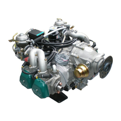
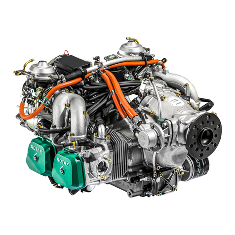
  9. Rotax 912 Series Operating and installation instructions

Rotax 912 Series Operating and installation instructions

SERVICE INFORMATION
SERVICE INFORMATIONSERVICE INFORMATION
2 UL 95-D/E
Aug. 1995
Seite/page 1 of 5
SERVICE INFORMATION
SERVICE INFORMATIONSERVICE INFORMATION
1) Wiederkehrende Symbole
Nachstehende wiederkehrende Symbole und Warnhinweise sind im Handbuch
enthalten. Diese Warnhinweise sind wichtig und unbedingt zu beachten.
▲WARNUNG: Vorsichtsregelnund-maßnahmen,derenNichtbeachtungzuVerletzungen
oder Tod führen kann
■ACHTUNG: Besondere Hinweise und Vorsichtsmaßnahmen, deren Nichtbeachtung zu
Beschädigungen des Motors oder anderer Bauteile führen kann.
◆HINWEIS: Besondere Hinweise zur Ergänzung oder zum besseren Verständnis einer
Instruktion.
2) Einführung:
Diese Informationen sollen dem Flugzeugbauer und Betreiber helfen, korrekte
Betriebsbedingungen und Installation zu gewährleisten und dadurch optimale Lei-
stung und Zuverlässigkeit zu erzielen.
3) Technische Daten und allgemeine Information über den Motor:
Ergänzend zu dieser Information ist folgendes zu beachten:
➪gültiges Motor-Handbuch
➪Technisches Datenblatt
➪Leistungs-, Drehmoment- und Verbrauchskurven
➪Aktuelle Ersatzteileliste
➪Einbauhinweise und -checkliste für den Motor
➪alle Service-Informationen über die betroffene Motortype
➪Reparaturhandbuch
Die Erfahrung hat gezeigt, daß bei Versäumnis von vorbeugender Wartung und
ungünstigen Betriebsbedingungen, es zu Funktionsstörungen am Vergaser kom-
men kann.
Nach eingehenden Untersuchungen wurde festgestellt, daß gewisse Faktoren,
einzeln oder in Verkettung, zu den nachfolgend angeführten Motorproblemen
beitragen können.
4) Gegenstand
Mögliche Vergaserverunreinigung
Schmutz im Vergaser, ROTAX 912-Serie
NUR ZUR INFORMATION.
ÄNDERUNGSDIENST NICHT VORGESEHEN.
1) Repeating symbols:
Please, pay attention to the following symbols throughout the service info. emphasiz-
ing particular information.
▲WARNING: Identifies an instruction, which if not followed, may cause serious injury or
even death.
■ATTENTION: Denotesaninstructionwhichifnotfollowed,mayseverelydamagetheengine
or other components.
◆NOTE: Information useful for better handling.
2) Introduction:
This information is intended to assist the aircraft designer, manufacturer and builder
toachievecorrectoperatingconditionsandassemblyfortheengineandconsequently
optimum performance and reliability.
3) Technical data and general information:
In addition to this technical reference please refer to:
➪current issue of the Operator´s Manual
➪engine data sheet
➪power, torque and fuel consumption curves
➪current issue of the spare parts list
➪engine installation instruction and installation check list
➪all service information regarding your engine
➪Repair Manual
Experiencehasshownthatpoorpreventivemaintenanceandunfavourableoperating
conditions might lead to operational trouble of the carburetors.
Extensive investigations have indicated that certain factors individually or in conjunc-
tion can contribute to the following engine problems.
4) Subject
Possible contamination of carburetors.
Contamination of carburetors, ROTAX-series 912
FOR INFORMATION ONLY.
WITHOUT COMMITMENT TO ADVISE MODIFICATIONS.
d02973
SERVICE INFORMATION
SERVICE INFORMATIONSERVICE INFORMATION
2 UL 95-D/E
Aug. 1995
Seite/page 2 of 5
5) Anlaß
Bei einigen Vergasern wurde Verunreinigung (Schmutz, Gummireste von Benzinlei-
tungen, Loctitereste, harzähnliche Substanz, Ablagerung usw.) in der Schwimmer-
kammer festgestellt.
▲WARNUNG: Diese Ablagerungen können möglicherweise Leerlauf- oder Haupt-
düsesowieanderefunktionswichtigeKanäleteilweiseoderkomplett
blockieren und zu Leistungsverlust oder Motorstop führen.
Alle Konstrukteure und Hersteller, Besitzer und Benützer von Flugzeugen, in denen
ROTAX-Motoren912eingebautsind,müssenalleEinbauhinweisefürdieseMotoren
befolgen, besonders die Einbauhinweise für das Kraftstoffsystem. Nichtbeachtung
der ordnungsgemäßen Installation und Mangel im Kraftstoffsystem kann zu Motor-
schäden führen. Nachstehend finden Sie Hinweise wodurch solche Schäden entste-
hen können.
5.1) Mögliche Fehler im Kraftstoffsystem (siehe auch Kapitel 5 in den Einbauhin-
weisen):
—Schmutz im Kraftstoffsystem
—Fehlender oder ungeeigneter Kraftstoffilter
—Verschmutzter Kraftstoffilter
—ungeeignete Kraftstoffleitungen
—Schmutz im Kraftstoffverteiler
—Ungeeignete Schwimmerkammerbelüftung
—Unzureichende Spülung des Kraftstoffsystems vor der Erstinbetriebnahme.
—Kraftstoffdruck zu niedrig bzw. zu hoch
5.2) Mögliche Fehler im Kraftstoff
Vorgeschriebene Qualitäts-Kraftstoffe verwenden.
—unverbleiter Tankstellen Normalbenzin, Minimum ROZ 90
—EN 228 Normal, EN 228 Super, EN 228 Super plus oder
—Benzin Mindestqualität 1, AKI 87.0 entsprechend kanadischer Norm CAN/
CGBS-3.5 (unverbleiter Automotiv-Kraftstoff) oder
—Kraftstoffe für Otto-Motoren entsprechend ASTM D 4814 oder
—AVGAS100 LL. AVGAS belastetdurch hohen BleianteildieVentilsitze höher
und bildet erhöhte Brennraumablagerungen. Es sollte daher nur im Falle von
DampfblasenproblemenoderwenndieanderenBenzinsortennichtverfügbar
sind, verwendet werden.
5) Reason
Severalcarburetorshavebeenfoundwithcontamination(dirt,remainsofrubberfrom
fuel lines and Loctite, resin-like substance, sediments etc.) in the float chamber.
▲WARNING: This contamination could possibly cause a partial or complete
blockage of the idle or main jet or of other ducts vital for operation,
leading to poor performance or stalling of engine.
Designers and builders as well as owners and users of aircraft powered by the
ROTAX 912 engine must follow all guidelines for the installation of these power
plants,especiallythedirectivesforthefuelsystem.Noncompliancewithdirectivesfor
proper engine installation and shortcomings in the fuel system might cause engine
failure. Statements about conditions which might cause problems in the fuel system
are listed below.
5.1) Possible shortcomings in the fuel system (consult also chapter 5 in the
installation instructions):
—dirt in the fuel system
—missing or unsuitable fuel filter
—soiled fuel filter
—unsuitable fuel lines
—dirt in fuel manifold
—poor float chamber venting
—insufficient flushing of the fuel system prior to initial engine operation
—fuel pressure too low or too high
5.2) Fuel criteria
Use only quality fuel as specified.
—regular gasoline, unleaded, minimum RON 90
—EN 228 regular, EN 228 premium, EN 228 Super plus or
—gasoline min. quality, AKI 87.0 in accordance to Canadian standards CAN/
CGBS-3.5 (unleaded automotive fuel) or
—fuels for spark ignition engines according to ASTM D 4814 or
—AVGAS 100 LL. Due to higher lead content in AVGAS, the wear of the valve
seats and deposits in the combustion chamber will increase. Therefore, use
AVGASonlyifyouencounterproblemswithvapourlocksorifotherfueltypes
are not available.
SERVICE INFORMATION
SERVICE INFORMATIONSERVICE INFORMATION
2 UL 95-D/E
Aug. 1995
Seite/page 3 of 5
6) Fristen
Unverzüglich Schwimmerkammer auf Verschmutzung überprüfen. Wird Schmutz
festgestellt ist das gesamte Kraftstoffsystem nach Angaben des Zellenherstellers zu
überprüfen.
7) Durchführung
Dieser Ratschlag beschreibt die Kontrolle und Reinigung des Vergasers und ist an
jedemderbeidenVergaser durchzuführen. Die IllustrationendazusindaufSeite4zu
sehen.
▲WARNUNG: Arbeiten nur bei kaltem Motor und geerdetem Fluggerät durchfüh-
ren.
— Batterie abschließen
— Tropftasse entfernen
— Federbügel Qnach vorne klappen und Schwimmerkammer Wsamt Dichtung E
vom Vergaser abnehmen
— Beide Schwimmer Rherausheben und sorgfältig auf Verunreinigung untersu-
chen.SchwimmerkammerentleerenundbeihellemLichtuntersuchen,davermu-
tete Ablagerungen am Boden schwierig erkennbar sind.
— Mit Druckluft ca. 5 bar beim Entlüftungsnippel Teinblasen und mit Fingern den
Luftaustritt unterhalb des Vergasers aus 2 vertikalen Bohrungen prüfen. Bei
Unsicherheit über freien Durchtritt sind die Bohrungen von Hand z. B. mit einem
Bohrer Ø 3 zu öffnen.
— Leerlaufdüse Uherausschrauben und auf freien Durchgang prüfen.
— Beide Schwimmer Rauf Leichtgängigkeit im Führungsstift Iüberprüfen. Wenn
derSchwimmerandertiefstenStelleliegt,mußdiesernochradialSpielhabenund
darfnichtanderAußenwandderSchwimmerkammerklemmen.Kontrollieren,ob
beideAbstandhalterOvorhandensind.EinhängengebliebenerSchwimmerführt
zum Überlaufen des Vergasers.
Die im Schwimmer eingepreßten Führungshülsen P auf Verschleiß prüfen. Die
Haltestifte {und die Schwimmerauflage }auf Verschleiß, hervorgerufen durch
übermäßigeVibrationen,kontrollieren.BeifeststellbaremVerschleißbeideSchwim-
mer und gegebenenfalls die Schwimmeraufhängung q erneuern.
— Parallelität der Schwimmeraufhängung überprüfen. Dazu die Hauptdüse w
demontieren und die Lehre e
TNr. 877 730
mit einer Sk-Schraube r auf den
Düsenstock schrauben.
6) Compliance
Inspectfloatchamber for contamination withoutdelay.At detection of contamination
examine the complete fuel system to directives of the aircraft builder.
7) Remedy
This advisory describes inspection and cleaning procedures which have to be
performed on each of the two carburetors. Refer to gage 4 for illustrations.
▲WARNING: Examinationto be carried out onthecoldengineandwithgrounded
aircraft only.
— disconnect battery
— remove trip tray
— fold out spring clip Qand remove float chamber Walong with gasket E.
— removebothfloatsRandinspectcarefullyforcontamination.Drainfuelfromfloat
chamber and inspect at bright light as the suspected residue is hard to detect on
float chamber bottom.
— Injectcompressedair(5bar/73p.s.i.)at ventnippleTandverifyairexit byfinger
on the two vertical bores at underside of carburetor. If free passage is doubtful
clear bores by hand e.g. with a Ø 3 drill.
— Remove idle jet Uand check for free passage.
— Check both floats Rfor easy movement on the guide pin I. With the float in its
lowest position it must be still clear and must not stick on wall of float chamber.
Check if both distance pieces Oare in position. A float stuck will cause the
carburetor to flood.
Check wear of guide sleeve P inserted in the float. Inspect the float pins {and
the float support }for wear caused by excessive vibration. At noticeable wear
replace both floats and float bracket q as required.
— Check if float bracket acts in parallel position. To verify remove main jet w and
attach gauge e
part.-no. 877 730
with a hex.hd. screw r to the mixing tube.
SERVICE INFORMATION
SERVICE INFORMATIONSERVICE INFORMATION
2 UL 95-D/E
Aug. 1995
Seite/page 4 of 5
I
O
Bild 3
0,5
-0,1
e
r
t
Bild 4
Bild 6
gut
good schlecht
bad
0,5 mm
i
o
po
Bild 1
Bild 5
Bild 2
SERVICE INFORMATION
SERVICE INFORMATIONSERVICE INFORMATION
2 UL 95-D/E
Aug. 1995
Seite/page 5 of 5
In geschlossener Nadelventil-Position müssen beide Schenkel der Schwimmer-
aufhängung einen gleichmäßigen Abstand von ca. 0,4 ÷0,5 mm haben. Bei
erkennbaremFehlerkanndieSchwimmeraufhängungentsprechendnachgebogen
oder erneuert werden. Nach erfolgter Prüfung Lehre wieder demontieren und
Hauptdüse einschrauben.
■ACHTUNG: Bei geschlossenem Schwimmernadelventil liegen die Schenkel
tparallel zum Vergaserkörper.
— Kontrolle des Schwimmernadelventiles.
Stift yaus der Lagerung ziehen und Schwimmernadelventil uherausziehen.
Vitonspitzeiprüfen.BeisichtbaremVerschleißder Bördelung obeim gefeder-
ten Stift pist das Ventil zu erneuern.
◆HINWEIS: Das Schwimmernadelventil ist nicht zerlegbar.
Wird der Abstand von 0,5 mm kleiner, beeinflußt dies auch das Schwimmer-
niveau, eventuell bis zur Sperre des Kraftstoffzuflusses.
— Hohlschraube [herausdrehen und Ringschlauchnippel ], Dichtung A und
Distanzhülse rentfernen. Kraftstoffkanal durchspülen und auf freiem Durch-
gang prüfen.
Klemmbügel Din der Schwimmeraufhängung Fund im Nadelventil einhängen.
Schwimmernadelventil in Position bringen und Schwimmeraufhängung mit Stift
yfixieren.
— Nach erfolgter Reinigung, Korkdichtung kontrollieren, Schwimmerkammer auf-
setzen und mit Federbügel fixieren, Vergaser wieder komplettieren.
— Kraftstoffleitungen anschließen.
— Batterieanschließen,elektrischeBenzinpumpeeinschalten, Schwimmerkammer
mit Benzin füllen und Schwimmerventil auf richtige Funktion überprüfen.
— Funktion der Vergaserbetätigung prüfen.
— Prüflauf durchführen.
▲WARNUNG: Wenn Sie eine Passage dieser Information nicht verstehen, oder wenn Sie
aus anderen Gründen die erforderlichen Überprüfungen oder Reparaturen
nicht durchführen können, wenden Sie sich, bitte, an Ihren nächsten autori-
sierten ROTAX Vertreter für Flugmotoren.
▲WARNUNG: Nichtbeachtung dieser Empfehlungen kann zu Motor- und Personen-
schaden führen!
In the closed position of the float valve both arms of the float bracket must be of
equaldistanceof0,4-0,5mm(.016-.02")Atnoticeableerror,thefloatbracketcan
be bent accordingly or be replaced. After the check remove the gauge and refit
main jet.
■ATTENTION: In the closed position of the float valve the arms tof the float
bracket have to be parallel to the carburetor body.
— Check of the float valve.
Removepinyfrommountingandwithdrawfloatvalveu.Inspectvitontipi.At
visiblewearofthe beaded edge othevalvehastobe renewed at the sprungpin
p.
◆NOTE: The float valve can´t be taken to pieces.
If the distance becomes less than 0,5 mm the float level will be affected too,
possibly to a complete interruption of the fuel flow.
— Remove banjo bolt [and hose nipple ], along with gasket A and spacer r.
Flush fuel duct and check for free passage.
Engage float needle clip Don float bracket Fand needle valve, place needle
valve in position and fix float bracket with pin y.
— Aftercleaningprocedure,inspectcorkgasket,fitfloatchamberandsecureitwith
spring clip; complete carb assembly.
— Connect fuel lines.
— Connect battery, switch on electric fuel pump, fill float chamber with fuel and
check float valve for proper operation.
— Check carburator actuation.
— Conduct test run.
▲WARNING: Ifany part ofthis information isnot fully understood orif for somereason the
required checks or repair work can´t be performed under personal control
please contact your next authorized ROTAX dealer.
▲WARNING: Non-compliance with these recommendations could result in engine
damage and personal injury.
Translation has been done to best knowledge and judgement-in any case the original text in German language is authoritative!
Other manuals for 912 Series

10

Other Rotax Engine manuals

Rotax 912 Series User manual

Rotax

Rotax 912 Series User manual

Rotax 912 Series User manual

Rotax

Rotax 912 Series User manual

Rotax 912 i series User manual

Rotax

Rotax 912 i series User manual

Rotax 503 UL User manual

Rotax

Rotax 503 UL User manual

Rotax 582 UL series User manual

Rotax

Rotax 582 UL series User manual

Rotax 915 i A SERIES Original operating manual

Rotax

Rotax 915 i A SERIES Original operating manual

Rotax 915 i A SERIES User manual

Rotax

Rotax 915 i A SERIES User manual

Rotax OM-912 User manual

Rotax

Rotax OM-912 User manual

Rotax 914 UL Series Operating and installation instructions

Rotax

Rotax 914 UL Series Operating and installation instructions

Rotax 377 User manual

Rotax

Rotax 377 User manual

Rotax 912 i series User manual

Rotax

Rotax 912 i series User manual

Rotax 912 Series User manual

Rotax

Rotax 912 Series User manual

Rotax 277 User manual

Rotax

Rotax 277 User manual

Rotax 125 MAX evo Operation and maintenance manual

Rotax

Rotax 125 MAX evo Operation and maintenance manual

Rotax 912 iS Sport User manual

Rotax

Rotax 912 iS Sport User manual

Rotax Leonardo 120 Instruction manual

Rotax

Rotax Leonardo 120 Instruction manual

Rotax 912 i series User manual

Rotax

Rotax 912 i series User manual

Rotax 125 MAX evo Troubleshooting guide

Rotax

Rotax 125 MAX evo Troubleshooting guide

Rotax 914 series User manual

Rotax

Rotax 914 series User manual

Rotax 912 i series Operating instructions

Rotax

Rotax 912 i series Operating instructions

Rotax 122 Operating instructions

Rotax

Rotax 122 Operating instructions

Rotax 912 i series Operating instructions

Rotax

Rotax 912 i series Operating instructions

Rotax 912 iSc Sport User manual

Rotax

Rotax 912 iSc Sport User manual

Rotax 912 Series User manual

Rotax

Rotax 912 Series User manual

Popular Engine manuals by other brands

Zenoah G230PU owner's manual

Zenoah

Zenoah G230PU owner's manual

Lincoln C Series owner's manual

Lincoln

Lincoln C Series owner's manual

Advantech AMAX-3245 user manual

Advantech

Advantech AMAX-3245 user manual

Neodrives Z20 user manual

Neodrives

Neodrives Z20 user manual

Perkins 4.2482 Workshop manual

Perkins

Perkins 4.2482 Workshop manual

brel-motors MJE24S quick start guide

brel-motors

brel-motors MJE24S quick start guide

Man B&W S80ME-C7 Project guide

Man

Man B&W S80ME-C7 Project guide

Danfoss EM-PMI540-T1500 user guide

Danfoss

Danfoss EM-PMI540-T1500 user guide

O.S. engine FSA-81 Owner's instruction manual

O.S. engine

O.S. engine FSA-81 Owner's instruction manual

Belimo VRD3-RE2-SET Installation

Belimo

Belimo VRD3-RE2-SET Installation

IAME Parilla Norswift 60cc user manual

IAME

IAME Parilla Norswift 60cc user manual

Bukh DV24 RME Owner's handbook

Bukh

Bukh DV24 RME Owner's handbook

Vetus M3.28 SOLAS Operation manual

Vetus

Vetus M3.28 SOLAS Operation manual

Stihl EVC 4000 instruction manual

Stihl

Stihl EVC 4000 instruction manual

Barrus SHIRE 70 WB manual

Barrus

Barrus SHIRE 70 WB manual

Hitachi SH7750 series Programming manual

Hitachi

Hitachi SH7750 series Programming manual

Assun AM-PI45115AN Series product manual

Assun

Assun AM-PI45115AN Series product manual

Omron MicroHAWK Integration guide

Omron

Omron MicroHAWK Integration guide

manuals.online logo
manuals.online logoBrands
  • About & Mission
  • Contact us
  • Privacy Policy
  • Terms and Conditions

Copyright 2025 Manuals.Online. All Rights Reserved.