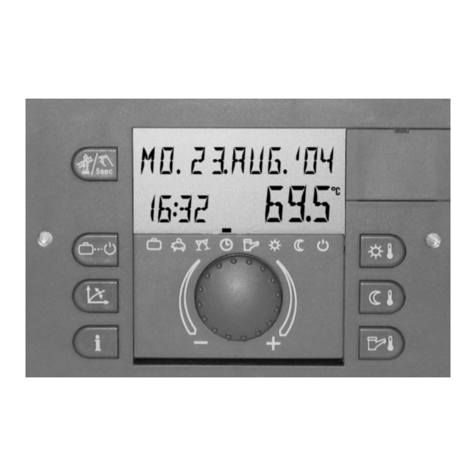
Rotex HPSU compact 304 User guide

ROTEX RoCon HP
Control System Instructions
Electronic controller for heat pumps
For the types
HPSU compact 304
HPSU compact 308
HPSU compact 508
HPSU compact 516
GB
Output03/2013
For certified companies

List of contents
2FA ROTEX RoCon HP - 03/2013
1 Safety . . . . . . . . . . . . . . . . . . . . . . . . . . . . . . 3
1.1 Observing instructions . . . . . . . . . . . . . . . . . . . . 3
1.2 Warning signs and explanation of symbols . . . . 3
1.2.1 Validity. . . . . . . . . . . . . . . . . . . . . . . . . . . . . . . . . . .3
1.3 Avoid danger . . . . . . . . . . . . . . . . . . . . . . . . . . . 3
1.4 Proper use . . . . . . . . . . . . . . . . . . . . . . . . . . . . . 3
1.5.1 Before working on the hydraulic system . . . . . . . . .4
1.5.2 Electrical installation . . . . . . . . . . . . . . . . . . . . . . . .4
1.5.3 Working on cooling systems (heat pump). . . . . . . .4
1.5.5 Instructing the user/owner. . . . . . . . . . . . . . . . . . . .4
2 Operation . . . . . . . . . . . . . . . . . . . . . . . . . . . 5
2.2.1 Display . . . . . . . . . . . . . . . . . . . . . . . . . . . . . . . . . .5
2.2.2 Operating elements. . . . . . . . . . . . . . . . . . . . . . . . .6
2.3 Basic functions and operating modes . . . . . . . . 6
2.3.3 Operating modes Standby, Reducing, heating,
cooling, Summer, Automatic 1, Automatic 2 . . . . . .8
2.3.4 Temperature setting Daytime room temperature . .8
2.3.5 Temperature setting Setback mode . . . . . . . . . . . .8
2.3.7 Configuration for hot water installation . . . . . . . . . .9
2.3.8 Switching time programme . . . . . . . . . . . . . . . . . . .9
2.3.9 Special functions . . . . . . . . . . . . . . . . . . . . . . . . . .10
2.4.1 Access rights (expert code). . . . . . . . . . . . . . . . . .10
2.4.2 Heat curve. . . . . . . . . . . . . . . . . . . . . . . . . . . . . . .11
2.4.4 Legionella protection. . . . . . . . . . . . . . . . . . . . . . .12
2.4.6 Screed function . . . . . . . . . . . . . . . . . . . . . . . . . . .12
2.4.7 Whisper mode . . . . . . . . . . . . . . . . . . . . . . . . . . . .13
2.4.9 Sensor test . . . . . . . . . . . . . . . . . . . . . . . . . . . . . .14
2.4.10 Remote control, Network function . . . . . . . . . . . . .14
2.5 User-specific settings . . . . . . . . . . . . . . . . . . . . 15
2.5.1 Switching time programme . . . . . . . . . . . . . . . . . .15
2.5.2 Parameter . . . . . . . . . . . . . . . . . . . . . . . . . . . . . . .16
3 Parameter settings . . . . . . . . . . . . . . . . . . 17
3.1 Explanation of the parameter tables . . . . . . . . 17
3.2 Rotary switch setting: Configuration . . . . . . . . 17
3.3 Rotary switch setting: DHW Installation . . . . . 22
3.4 Rotary switch setting: Operating Mode . . . . . . 23
3.5 Rotary switch setting: Set Temp Day . . . . . . . 23
3.6 Rotary switch setting: Set Temp Night . . . . . . 23
3.7 Rotary switch setting: DHW Set Temp . . . . . . 23
3.8 Rotary switch setting: Time Program . . . . . . . 24
3.9 Rotary switch setting: Info . . . . . . . . . . . . . . . . 25
3.10 Rotary switch setting: Basic Configuration . . . 26
3.11 Operating button: Sonderfunktion . . . . . . . . . . 26
4 Faults and malfunctions . . . . . . . . . . . . . . 27
4.1 Troubleshooting . . . . . . . . . . . . . . . . . . . . . . . . 27
4.1.1 Current fault display . . . . . . . . . . . . . . . . . . . . . . .27
4.1.2 Reading the fault memory . . . . . . . . . . . . . . . . . . .27
4.3 Fault codes . . . . . . . . . . . . . . . . . . . . . . . . . . . 31
4.4 Configuration DIP switch . . . . . . . . . . . . . . . . . 34
5 Glossary . . . . . . . . . . . . . . . . . . . . . . . . . . . 35
6 List of keywords . . . . . . . . . . . . . . . . . . . . 36
7 Notes. . . . . . . . . . . . . . . . . . . . . . . . . . . . . . 37

1xSafety
FA ROTEX RoCon HP - 03/2013 3
1Safety
1.1 Observing instructions
This instruction is the >> Original Version << in your language.
All the activities required for operation and setting the parameters
are described in this instruction manual. All parameters needed
for trouble-free operation have been configured at the factory.
ƔPlease read through this manual carefully before operating
the heating system or before adjusting the settings for it.
ƔMake a note of the preset values before you make any
changes to the unit configuration.
Relevant documents
– ROTEX HPSU compact; the associated installation and oper-
ating instructions the operating instructions for the end cus-
tomer and the operating manual for the operator.
– External unit for ROTEX HPSU compact; the associated
installation and operating instructions.
– With connection of a ROTEX Solaris solar system; the asso-
ciated installation and operating instructions.
– With connection of a ROTEX HP convectors; the associated
installation and operating instructions.
The guides are included in the scope of supply for the individual
units.
1.2 Warning signs and explanation of symbols
Meaning of the warnings
Warnings in this manual are classified according into their
severity and probability of occurrence.
Special warning signs
Some types of danger are represented by special symbols:
1.2.1 Validity
Some information in this manual has limited validity. The validity
is highlighted by a symbol.
Order number
Notes related to order numbers are identified by the shopping
cart symbol .
Handling instructions
ƔInstructions on actions are shown as a list. Actions of which
the sequential order must be maintained are numbered.
ÎResults of actions are identified with an arrow.
1.3 Avoid danger
The ROTEX HPSU compact is state-of-the-art and is built to meet
all recognised technical requirements. However, improper use
may result in serious physical injuries or death, as well as
property damage.
To avoid danger, only operate the ROTEX HPSU compact:
– as stipulated and in perfect condition,
– with an awareness of the safety and hazards involved.
This assumes knowledge and use of the contents of this manual,
the relevant accident prevention regulations and the recognised
safety-related and occupational medical rules.
1.4 Proper use
The ROTEX RoCon controller must be used exclusively in the
type HPSU compact. The ROTEX RoCon controller must only
operated only according to the indications in this manual.
Any other use outside the intended use is considered as
improper. The operator alone shall bear responsibility for any
resulting damage.
Use as intended also involves compliance with maintenance and
inspection conditions. Spare parts must at least satisfy the
technical requirements defined by the manufacturer. This is the
case, for example, with original spare parts.
DANGER!
Draws attention to imminent danger.
Disregarding this warning can lead to serious injury or
death.
WARNING!
Indicates a potentially dangerous situation.
Disregarding this warning can result in serious injury
or death.
CAUTION!
Indicates a situation which may cause possible
damage.
Disregarding this warning can lead to damage to
property and the environment.
This symbol identifies user tips and particularly useful
information, but not warnings or hazards.
Electric power
Only valid for ROTEX HPSU compact with heating and
cooling function
WARNING!
This unit is not intended for use by persons (including
children) with impaired physical, sensory or mental
faculties or persons with insufficient experience and/or
expertise unless supervised by a person responsible
for ensuring their safety or are given instruction by this
person on how to use the unit.

4FA ROTEX RoCon HP - 03/2013
1xSafety
1.5 Instructions for operating safety
1.5.1 Before working on the hydraulic system
ƔWork on the ROTEX HPSU compact (such as setup,
servicing, connection and initial start-up) is only to be carried
out by persons who are authorised and who have success-
fully completed qualifying technical or vocational training and
who have taken part in advanced training sessions recog-
nised by the appropriate responsible authorities. This, in
particular, includes heating specialists and climate control
technicians who have experience, as a result of their
technical training and their knowledge of the subject, of
proper and appropriate installation and maintenance of
heating, climate control and cooling installations and heat
pumps.
ƔSwitch off the mains supply before starting any work on the
ROTEX HPSU compact and secure it against unintentional
switch-on.
ƔSeals must not be damaged or removed.
ƔOnly original ROTEX replacement parts may be used.
1.5.2 Electrical installation
ƔElectrical installation may be carried out only by electrical
engineers and in compliance with the valid electro-technical
guidelines as well as the regulations of the relevant energy
supply company (EVU).
ƔCompare the mains voltage (~230 V, 50 Hz or ~400 V, 50 Hz)
indicated on the type plate with the supply voltage before
connecting to the mains.
ƔBefore beginning work on live parts, disconnect them from the
power supply (switch off main switch, remove fuse) and
secure against unintentional restart.
ƔEquipment covers and service panels must be replaced as
soon as the work is completed.
1.5.3 Working on cooling systems (heat pump)
ƔAlways wear safety goggles and protective gloves.
ƔWhen working on the refrigerant circuit, ensure that the
workplace is well ventilated.
ƔNever carry out work on the refrigerant circuit in closed rooms
or work pits.
ƔDo not let refrigerant come into contact with open fire, embers
or hot objects.
ƔNever allow refrigerant to escape into the atmosphere (high
pressure at the point of the leak).
ƔWhen removing the service pipes from the filling connections,
never hold the connections in the direction of your body.
Residual refrigerant could escape.
ƔComponents and spare parts must at least satisfy the
technical requirements defined by the manufacturer.
1.5.4 Operation
The ROTEX HPSU compact:
ƔDo not operate until all installation and connection work is
completed.
ƔOnly operate with a completely full storage tank (Level
indicator) and heating circuit.
ƔOnly connect with a pressure reducer on the external water
supply (supply line).
ƔOperate at a maximum pressure of 3 bar.
ƔOnly operate the with the specified quantity of refrigerant and
the type of refrigerant specified.
Ɣonly operate if the protective cover is installed.
The specified servicing intervals should be adhered to and
inspection work must be carried out.
1.5.5 Instructing the user/owner
ƔBefore you hand over the ROTEX HPSU compact, explain to
the user/owner how to operate and check the system.
ƔHand over the technical documentation (this document and
all supporting documents) to the user and advise him that
these documents must be made available at all times and be
stored in the immediate vicinity of the unit.
ƔMake a record of the handover by filling out and signing the
installation and instruction forms jointly with the user/owner.
For work on stationary refrigeration systems (heat
pumps) and air conditioning systems, proof of expertise
is required in the European Community according to
the F-Gases Directive (EC) No. 842/2006.
– up to 3 kg coolant fill quantity: Stationary equip-
ment qualification category 2
– 3 kg coolant fill quantity or over: expert certifi-
cate category 1

2xOperation
FA ROTEX RoCon HP - 03/2013 5
2 Operation
2.1 General 2.2 Display and operating elements
2.2.1 Display
All the operating steps are supported by appropriate displays in
the clear text display. Menu guiding is available in 6 different
languages (see section 2.3.1).
DANGER!
If electrical components come into contactwith water,
this can cause an electric shock as well as cause
potentially fatal injuries and burns.
ƔProtect the displays and keys on the control
systems from the effects of moisture.
ƔTo clean the display, use a dry cotton cloth.
Using aggressive cleaning agents and other
liquids can cause damage to equipment or lead
to an electric shock.
Maximum energy utilisation
The most effective energy utilisation is achieved by the
unit at the lowest possible return flow and hot water
temperatures.
At temperatures in excess of 50°C, the effectiveness
(COP) of the HPSU compact will be made worse by
the heatingsupport provided by the optional heater
(backup heater).
The safety settings of the HPSU compact hinder the
operation of the heat pump if
– the outdoor temperature is <12°C and simultane-
ously
– the storage tank temperature is <30°C.
Without backup heater:
At an outdoor temperature <12°C, the storage tank
water needs to be heated up by an external heater to
>30°C.
With backup heater (BUH):
At an outdoor temperature <12°C, the backup heater
(BUH) switches on automatically to heat the water in
the storage tank to >30°C.
ƔIn order to accelerate the heating up process with
BUH, temporarily set the
– Parameter [T-DHW 1 des] >55°C,
– Parameter [Function Heating Rod] = "1" and
– Parameter [BOH power] = 9000 W.
1 Clear text display
2 Setting: Configuration
3 Not assigned
4 Rotary switch
5 Setting: Info
6 Setting: Operating Mode
7 Setting: Set Temp Day
8 Setting: Set Temp Night
9 Setting: DHW Set Temp
10 Rotary button
11 Setting: DHW Installation
12 Setting: Time Program
13 Operating button
Fig. 2-1 Arrangement of display and operating elements
1 Date display
2 Status of refrigerant
compressor
3 Display of expert login
4 Display time
5 Current flow temperature
(heating circuit)
6 Status heating circuit
7 Current outdoor temperature
8 Active heating programme
9 Status of hot water genera-
tion
10 Current storage tank temper-
ature
Fig. 2-2 Controller display

6FA ROTEX RoCon HP - 03/2013
2xOperation
2.2.2 Operating elements
If special key combinations or extended key pushes are required
for certain function, a separate note is made in each specific
section of this description.
Rotary switch
The rotary switch is used to gain rapid direct access (main
function level) to frequently required functions and setting possi-
bilities.
Tab. 2-1 Function of rotary switch
Rotary switch
The rotary switch can be used to navigate in the individual levels,
setting values can be selected and these settings can then be
accepted by pressing briefly.
Tab. 2-2 Functions of the rotary switch
Operating button
This button can be used to jump back to the previous display
within a menu display or a function / input can be interrupted.
This button can also be used to call up the special level
(see section 2.3.9).
Tab. 2-3 Functions of the operating button
2.3 Basic functions and operating modes
If the installation is switched on, it regulates the following
operating modes fully-automatically based on the settings in the
controller:
– Room heating or room cooling
– Water heating
The operating mode can be affected by additional functions:
– Interlink Function
– Weather-dependent target value regulation
– Switching time programme
– Setting the temperature target value
– Room thermostat
– Whisper mode
– SMART GRID - Signal
– EVU (reduced cost tariff) - Signal
If the user enter a value manually, this setting remains active until
the user changes it or until the program clock forces another
setting.
CAUTION!
Never operate the operating elements on the
controller with a hard, pointed object. This can cause
damage and can cause the control to malfunction.
Fig. 2-3 Illustration of main function level (rotary switch position)
Independent of the setting of the rotary switch, the
HPSU compact operates in accordance with the
operating mode set in the switch position "Operating
Mode" or which has been activated by a special
programme.
Action Result
Rotating
Direct selection of the main function level allo-
cated to this switch position.
Action Result
Rotating
To the right (+): Increased regulation
To the left (–): Reduced regulation
tap sthing
Confirm, accept, execute selection.
Info
(section 2.3.2)
Basic Configuration
(Not assigned)
Configuration
(section 2.3.1)
Time Program
(section 2.3.8)
DHW Installation
(section 2.3.7)
Operating Mode
(section 2.3.1)
Set Temp Day
(section 2.3.4)
Set Temp Night
(section 2.3.5)
DHW Set Temp
(section 2.3.6)
Action Result
Brief actuation. – Jump back to the previous display or pre-
vious level.
Press for more
than 5 secs.
– Special level is called up.

2xOperation
FA ROTEX RoCon HP - 03/2013 7
Switching the system on and off
The system is switched on and off at the rotary switch in the
position "Operating Mode" (See section 2.3.3 for
procedure).
Water pressure display
When switched on, the controller can be used to display the
system pressure (water pressure) of the internal circuit (heating
circuit) (see section 2.3.2 for procedure).
The water pressure should be between 1.5 and 3.0 bar in heating
mode. If it is less than 1.5 bar, the water pressure must be
increased by refilling the system (see heat generator installation
instructions).
Thawing (automatic function)
At low outdoor temperatures and corresponding humidity values,
the external heat pump unit may ice up. This icing impairs
efficient operation. The system detects this condition automati-
cally and starts the melting operation. After 8 minutes at most, the
system returns to normal mode.
2.3.1 Standard settings
In the rotary switch position "Configuration" , we carry out
setting of the regulation and the system configuration for the
installation environment of the HPSU compact, its integrated
heating circuit, the hot water generation and possibly the option-
ally connected components.
Depending on the login (expert code), various settings are only
accessible by the heating expert.
Language, date, time, summer time
ƔPlace the rotary switch in the "Configuration" position.
ÎAn overview is displayed.
ƔSelect the "Installation" level with the rotary switch.
ÎAn overview is displayed.
ƔUse the rotary switch to select the parameters [language],
[Date], [Time] or [Summertime].
ƔSelect and change the value to be changed within the
individual display using the rotary switch.
ƔConfirm the changes with a brief push of the rotary switch.
ÎChange has been accepted. Jump back to previous dis-
play.
More detailed explanations and possible setting values for this rotary switch setting
can be seen in section 2.4 and in chapter 3.2.
Display settings
ƔPlace the rotary switch in the "Configuration" position.
ÎAn overview is displayed.
ƔSelect the "Installation" level with the rotary switch.
ÎAn overview is displayed.
ƔUse the rotary switch to select the parameters
[LCD Contrast], [LCD Brightness], [LCD Illum Time] or
[RGB Setup].
ƔSelect and change the value to be changed within the
individual display using the rotary switch.
ƔConfirm the changes with a brief push of the rotary switch.
ÎChange has been accepted. Jump back to previous dis-
play.
More detailed explanations and possible setting values for this rotary switch setting
can be seen in chapter 3.9.
Interlink function
This setting allows the facility for the HPSU compact to operate
with 2 different set values, where the second set value is 5 K over
the set value. This applies both to a weather-controlled controller
and for control using a fixed flow temperature.
More detailed explanations and possible setting values for this rotary switch setting
can be seen in chapter 3.2.
Fig. 2-4 Switching the system on and off
Fig. 2-5 Indicating the system pressure
+-
+-
Operating Mode
Standby
Reducing
Operating Mode
heating
cooling
Summer
Operating Mode
Summer
Automatic 1
Automatic 2
+-
+-
Info
T-HS
T-HS des
Info
T-HC Setpoint
Water Pressure
Runtime Compressor
Water Pressure
+2.5 bar
An internal pre-programmed calendar ensures
automatic time reset at the annually recurring
summer/winter time changes. If required, the automatic
time changeover can be switched off.

8FA ROTEX RoCon HP - 03/2013
2xOperation
2.3.2 System information
This rotary switch setting serves exclusively for displaying values
such as the current system temperatures, operational conditions,
consumption values and software information.
No settings can be made to these values.
ƔPlace the rotary switch in the "Info" position.
ÎAn overview is displayed.
ƔSelect the desired information level with the rotary switch.
ÎAn overview is displayed.
ƔSelect the individual information with the rotary switch.
More detailed explanations and possible setting values for this rotary switch setting
can be seen in chapter 3.9.
2.3.3 Operating modes Standby, Reducing, heating,
cooling, Summer, Automatic 1, Automatic 2
In this rotary switch position we stipulate the operating mode that
the HPSU compact should operate in.
ƔPlace the rotary switch in the "Operating Mode"
position.
ÎAn overview is displayed.
ƔSelect the desired operating mode with the rotary switch.
ƔConfirm the changes with a brief push of the rotary switch.
ÎHPSU compact operates in accordance with the set oper-
ating mode.
Standby (Stand-by)
In this mode, the HPSU compact is placed in stand-by mode. This
should only take place if the HPSU compact is not working at the
time. The frost-protection function remains in place. Below the
parameter value [T-Frost Protect] the integrated circulation pump
is switched on in order to prevent the heating system from freez-
ing.
In order to maintain this function, the system must not be discon-
nected from the mains!
Reducing
Reduced heating mode (lower set room temperature) in
accordance with the setback temperature set in the parameter
[T-Reduced] (see section 2.3.5).
heating, cooling
Heating or cooling in accordance with the temperature set in the
parameter [T-Room des 1] (see section 2.3.4).
An outdoor temperature sensor (weather-controlled regulation)
or a connected room station will also influence the set temper-
ature regulation.
Summer
Hot water mode in accordance with the temperature set in
parameter [T-DHW 1 des] (see section 2.3.6) or, if set, a
permanent hot water timer programme:
– [DHW Program 1]
– [DHW Program 2]
Automatic 1
Automatic heating and setback mode in accordance with the
permanent timer programmes (see section 2.3.8):
– [HC Program 1]
– [DHW Program 1]
Automatic 2
Automatic heating and setback mode in accordance with the
permanent timer programmes (see section 2.3.8):
– [HC Program 2]
– [DHW Program 2]
2.3.4 TemperaturesettingDaytimeroomtemperature
In this rotary switch setting we determine the daytime tempera-
tures for the room heating or cooling.
ƔPlace the rotary switch in the "Set Temp Day" position.
ÎAn overview is displayed.
ƔSelect the temperature block to be set with the rotary switch.
ÎSettings are displayed.
ƔSet the temperature.
ƔConfirm the change with a brief push of the rotary switch.
ÎChange has been accepted. Jump back to previous dis-
play.
More detailed explanationsand possible setting values for this rotary switch setting
can be seen in chapter 3.5.
2.3.5 Temperature setting Setback mode
In this rotary switch setting we determine the setback mode
temperatures for the room heating or cooling.
ƔPlace the rotary switch in the "Set Temp Night" position.
ÎAn overview is displayed.
ƔSelect the parameter to be set with the rotary switch.
– [T-Reduced]: Set value for operating mode [Reducing] or
setback by a permanent timer programme.
– [T-Absence]: Set value for a one-off timer programme.
ÎSettings are displayed.
ƔSet the temperature.
ƔConfirm the change with a brief push of the rotary switch.
ÎChange has been accepted. Jump back to previous dis-
play.
More detailed explanationsand possible setting values for this rotary switch setting
can be seen in chapter 3.6.
If a one-off timer programme is started during the
selected operating mode, the regulation will take place
with preference according to the settings of this timer
programme.
CAUTION!
A heating system that is not frost-protected can freeze
in cold weather and be damaged.
ƔDrain the water out of the heating system if there is
a danger of frost.
ƔIf the heating system is not drained, the power
supply must be ensured and the main switch must
remain switched on.
The end figures of the parameter designations (1 - 3)
within this rotary switch setting designate the associ-
ation with each individual timer programme.
The 1st. set value (parameter) is used for one-off timer
programmes and in an operating mode with an
immediate heating/cooling demand as the set value.

2xOperation
FA ROTEX RoCon HP - 03/2013 9
2.3.6 Temperature setting Hot water mode
In this rotary switch setting we determine the temperatures for hot
water generation in the individual timer programmes.
ƔPlace the rotary switch in the "DHW Set Temp" position.
ƔThe rest of the process for temperature setting for hot water
generation is identical to section 2.3.4.
More detailed explanations and possible setting values for this rotary switch setting
can be seen in chapter 3.7.
2.3.7 Configuration for hot water installation
In this rotary switch setting we can make settings for the
incorporation of the optional backup heater with regard to the hot
water mode for the HPSU compact.
Possible setting values for this rotary switch setting can be seen in chapter 3.3.
2.3.8 Switching time programme
In this rotary switch setting we set the time intervals for the heat-
ing circuit, the integrated hot water generation and the optional
circulation pump.
Various different timer programmes are available, that are set in
the factory, but which can be adjusted to suit, to provide
convenient and individual room and hot water temperature
control.
Adjustment
ƔPlace the rotary switch in the "Time Program"
position.
ÎAn overview is displayed.
ƔSelect the timer programme to be set with the rotary switch.
ÎSettings are displayed.
ƔSelect and change the value to be set with the rotary switch.
ƔConfirm the changes with a brief push of the rotary switch.
More detailed explanations and possible setting values for this rotary switch setting
can be seen in chapter 3 "Parameter settings".
Permanent timer programmes
Timer programmes regulate the heating circuit temperatures for
the heating circuit, storage tank charging circuit and the circu-
lation pump, according to the stipulated switching cycles. The
switching cycles are saved in various different timer blocks.
In the switching cycles the heating system is regulated differen-
tiated into day and setback mode.
The temperature settings for this timer programme are carried out
via the set value settings "Set Temp Day" , "Set Temp
Night" and "DHW Set Temp" .
The following switching time programmes are available:
– 2 timer programmes for heating, cooling circuit, each with 3
possible time blocks
– [HC Program 1]
– [HC Program 2]
Fig. 2-6 Menu structure heating circuit timer programme
– 2 timer programmes for the hot water circuit, each with 3 pos-
sible time blocks
– [DHW Program 1]
– [DHW Program 2]
– 1 timer programme for the circulation circuit, each with 3 pos-
sible time blocks
– [Circulation Time]
The end figures of the parameter designations (1 - 3)
within this rotary switch setting designate the associ-
ation with each individual timer programme.
The 1st. set value (parameter) is used for one-off timer
programmes and in an operating mode with an
immediate heating demand as the set value.
The regulation is carried out according to the operating
mode defined in the timer programmes. The hot water
generation operates continuously in accordance with
the hot water temperature set in each case.
Below the frost protection temperature (parameter
[T-Frost Protect]), the heating circuit temperatures are
regulated automatically according to the setback
operating mode. The integrated circulation pump is
switched on in order to prevent the heating system from
freezing.
A separate input for each individual day of the week is
possible, or in blocks of "Monday to Friday", "Saturday
to Sunday" and "Monday to Sunday".
Programme Time period Time block
HC Program 1 Single day of the week
(Monday, Tuesday ...)
1.
2.
3.
06:00 -> 22:00
--:-- -> --:--
--:-- -> --:--
Working week
(Monday to Friday)
1.
2.
3.
06:00 -> 22:00
--:-- -> --:--
--:-- -> --:--
Weekend
(Saturday to Sunday)
1.
2.
3.
07:00 -> 23:00
--:-- -> --:--
--:-- -> --:--
Entire week
(Monday to Sunday)
1.
2.
3.
06:00 -> 22:00
--:-- -> --:--
--:-- -> --:--
HC Program 2 See HC Program 1
1.
2.
3.
See
HC Program 1
Settings of a time block in a time period are also taken
over by other time periods (provided that they refer to
the same days of the week). Examples referring to
fig. 2-6:
a) For the single working day "Monday" the start time
in the 1st. time block is changed from 06:00 to
05:00.
ÎIn the time period "Working week" and "Entire
week", the 1st. time blockis also changed from
06:00 to 05:00.
b) For the time period "Weekend", the start time in the
1st. time block is changed from 07:00 to 08:00.
ÎIn the individual weekdays "Saturday" and "Sun-
day", the 1st. time block is automaticallyis also
changed from 07:00 to 08:00.
c) For the time period "Entire week", the end time in
the 1st. time block is changed from 22:00 to 21:30.
ÎIn all the time periods the 1st. time block is also
changed from 22:00 to 21:30.
The setting and input structure of the timer programmes
are identical to the ones for the heating circuit timer
programme (see also fig. 2-6).

10 FA ROTEX RoCon HP - 03/2013
2xOperation
Saved time switching programs can be changed or deleted at any
time. To have a better overview, we recommend making a record
of the programmed switching times and keeping this in a safe
place (see section 2.5.1).
One-off timer programmes
For a specific situation there are 4 one-off programmes
available, which deactivate the planned timerprogrammes for
the duration of their validity.
The temperature settings for this timer programme are carried out
via the set value settings "Set Temp Day" , "Set Temp
Night" and "DHW Set Temp" .
– 1 timer programme for an immediate one-off extension of
the heating time (room heating, room cooling and hot water).
–[Party]
– 1 timer programme for an immediate one-off setback up to
6 h. The setback temperature is set in the rotary switch set-
ting "Set Temp Night" , in the parameter [T-Absence].
–[Away]
– 1 timer programme for a one-off calendar-controlled set-
back. The setback temperature is set in the rotary switch set-
ting "Set Temp Night" , in the parameter [T-Absence].
– [Holiday]
– 1 timer programme for a one-off calendar-controlled regu-
lation. The setback temperature is set in the rotary switch
setting "Set Temp Night" , in the parameter [T-Absence].
– [Vacation]
2.3.9 Special functions
In this programme the hand mode can be started and saved
faults can be read out.
The following special functions are possible:
– Hand mode (manual regulation of the flow temperature to a
specific value).
– Fault (displays the last 10 faults)
More detailed explanations of these functions can be found in chapter 3.11.
ƔPress operating key for at least 5 s.
ÎMenu "Special Level" is displayed.
ƔSelect the programme to be started with the rotary switch.
ƔConfirm the changes with a brief push of the rotary switch.
ÎThe selected programme starts.
ƔInterruption and jump back with operating button.
2.4 Special system settings
The controller is pre-configured for the HPSU compact but will
need to be adapted to an optionally connected accessory and to
the installation environment before commissioning.
Adaption is carried out via the setting of parameters on the
controller. The setting on the rotary switch determines the main
parameter group.
Navigating with the rotary switch accesses either the next
deepest level or directly to the appropriate parameter, depending
on the setting on the rotary switch.
Certain settings in the controller are restricted by access rights.
In order to gain access to these setting values (parameters), you
need to enter the expert code in this menu.
2.4.1 Access rights (expert code)
The setting and input structure of the timer programmes
are identical to the ones for the heating circuit timer
programme (see also fig. 2-6).
The call-up of special functions does not depend on the
setting on the rotary switch.
Fig. 2-7 Login heating specialist
+-
+-
+-
+-
+-
+-
+-
4x
Installation
System Configuration
Access Rights
User
Access Rights
Expert
Configuration
LCD Contrast
LCD Brightness
Installation
Keylock Function
Access Rights
Interlinc fct
Installation

2xOperation
FA ROTEX RoCon HP - 03/2013 11
2.4.2 Heat curve
With the heating characteristic curve, the heating output is
adjusted to the building conditions in accordance with the
relevant external temperature. Generally speaking, the
steepness of the heating characteristics describes the ratio of the
flow temperature change to the external temperature change.
The heating characteristic curve applies within the minimum and
maximum temperature limits that have been set for the corre-
sponding heating circuit. The room temperature measured in the
living area may differ from the desired room temperature; these
deviations can be kept to a minimum by installing a room
thermostat or a room station.
The controller is set in the factory so that the heat curve does
not adjust itself during operation.
The automatic heat curve adaption can be activated
(parameter [HC Adaption]), if the outdoor temperature sensor
(RoCon OT1, 15 60 70) or the room station (RoCon U1,
15 70 34) are connected (see section 2.4.3).
If an automatic heat curve adaption is not activated, the heat
curve can be set manually by adjusting the parameter [Heat-
Slope]).
More detailed explanations and possible setting values for this function can be seen
in chapter 3.2.
CAUTION WITH UNDERFLOOR HEATING!
In the event of a fault, or in hand mode, damage may
be caused to the screed, the structure of the floor and
the underfloor heating system by overheating.
ƔBefore starting for the first time you must always
install a controller-independent maximum temper-
ature limiter (e.g. a system thermostat where the
control phase of the heating circuit pump is looped
via the switching contacts).
ƔSet the controller-independent maximum temper-
ature limitation (parameter [T vbh1 max]) to the
maximum permissible system temperature.
Setting to suit:
Do not make any corrections to the set values for 1 - 2
days, and then only make them in small increments.
ƔDeactivate additional heat sources (e.g. fireplaces,
direct solar radiation, open windows).
ƔFully open any radiator thermostats.
ƔActivate the "HEATING" mode.
Approximate setting values:
– Radiator and system 70: 1.4 to 1.6 (factory setting
1.5)
– Underfloor heating system: 0.5 to 0.9 (factory set-
ting 1.0)
Fig. 2-8 Manual setting heat curve
TAExternal temperature
TVFlow temperature heat generator
TRRoom temperature set value
Fig. 2-9 Heat curves
+-
+-
+- +-
+-
+-
0.70
0.0 3.00
Installation
System Configuration
Configuration
Configuration
System Configuration
CH Configuration
DHW Configuration
Operating Mode
heating
CH Configuration
CH Configuration
Operating Mode
heating
cooling
heating
T-Outside Limit Day
T-Outside Limit Night
heating
T-Outside Limit Night
Heat-Slope
Room Influence
Heat-Slope

12 FA ROTEX RoCon HP - 03/2013
2xOperation
2.4.3 Weather-dependent set value regulation
If the "weather-controlled set value regulation" is active, the flow
temperature is determined automatically, depending on the
outdoor temperature (outdoor temperature sensor RoCon OT1):
Colder outside temperatures result in warmer water and vice
versa.
If, in addition, the room station (RoCon U1, 15 70 34) is
connected to the ROTEX HPSU compact, the RoCon HP
regulates the set temperature in a weather and room temperature
controlled manner.
The target settings in the parameter settings determine the
specified values to be attained in weather-dependent operation.
Activation and deactivation of this function takes place via the
parameter [HC Function] in the rotary switch position
"Configuration" in level "CH Configuration".
– Parameter [HC Function] = 0: Weather-controlled regulation
– Parameter [HC Function] = 1: Regulation to fixed set temper-
ature value
More detailed explanations and possible setting values for this function can be seen
in chapter 3.2.
2.4.4 Legionella protection
The ROTEX HPSU compact itself does not need this function
because of the small volume of the internal drinking water heat
exchanger.
This function is only required with connected hot water storage
tanks with larger volume drinking water capacities (>400 l). If the
legionella protection function is active, thermal disinfection is
carried out to prevent the hot water storage tank becoming
contaminated with bacteria. This involves heating the storage
tank to a disinfection temperature 1 x a day or 1 x a week. The
legionella protection function is active for 1 hour.
Setting the parameters for legionella protection is carried out in
the rotary switch setting "Configuration" in level "DHW
Configuration".
Using the factory settings, the storage tank is charged at 00:15
hours if the hot water temperature is below 65°C at that time.
More detailed explanations and possible setting values for this function can be seen
in chapter 3.2.
2.4.5 Reset
In certain situations, e.g. if the boiler is not functioning properly
after making a setting, it may be necessary to return the settings
to the factory settings.
The controller offers the possibility of resets in 3 various different
levels and therefore saves having to completely reconfigure all
the parameters.
ƔPlace the rotary switch in the "Configuration" .
ÎAn overview is displayed.
ƔUse the rotary switch to select the level
–"System Configuration" (1st. reset possibility)
or
–"CH Configuration" (2nd. reset possibility)
or
–"DHW Configuration" (3rd. reset possibility).
ÎAn overview is displayed.
ƔSelect the parameter [Reset?] with the rotary switch.
ƔConfirm the changes with a brief push of the rotary switch.
ÎReset is carried out. Jump back to previous display.
More detailed explanations and possible setting values for this function can be seen
in chapter 3.2.
2.4.6 Screed function
The screed function is intended exclusively for specified drying of
newly created screed in underfloor heating systems. Here we
use, as a basis, the recommendation of the Federal Association
Surface Heaters for Curing Heating (heating in accordance with
the stipulated temperature profile).
The heating of the screed is possible differentiated with the
function heating and the curing heating.
The screed function is a special function and is not interrupted
by any other operating mode. It can be activated only by the
heating expert and only for the direct heating circuit.
All weather-guided control functions for the relevant heating
circuit are switched off when the screed function is activated.
The relevant heating circuit operates independently of the
operating mode (switching times) as a constant temperature
regulator. The maximum temperature is determined by the
relevant maximum flow temperature limiter.
An already activated screed function can be deactivated at any
time. At the end of the screed function the parameter is automat-
ically set to "OFF" and the heating circuit once again operates
according to the currently set operating mode.
CAUTION!
If hot water is used during the disinfection phase, there
is a risk of fluctuations in the hot water storage tank
temperature and, thus, of scalding.
ƔIf hot water is required during the disinfection
phase, it must be mixed with cold water.
ROTEX always recommends fitting a scald protection
in the hot water distribution line (e.g. VTA32,
15 60 16).
The maximum hot water temperature set by the user or
the heating technician is ignored when hot water is
heated for disinfection purposes.
The procedure for setting in the parameter level is
described in the installation instructions of the heat
generator, chapter "Commissioning".

2xOperation
FA ROTEX RoCon HP - 03/2013 13
Function heating
Function heating verifies that the installation is fault-free for the
heating engineer. A pre-printed heating up report, referring to
ROTEX underfloor heating can be found at the internet portal at
http://www.rotex.de.
In this case, function heating (identical with "Heating up" in
EN 1264, section 5.2) does not constitute a heating up process
for drying and curing. Normally you need to carry out separate
heating process to cure the floor and/or perform mechanical
drying.
Heating up should be carried out no earlier than after 21 days for
cement screed, and no earlier than after 7 days for anhydrite
screed in accordance with the details provided by the manufac-
turer. The first heating up starts at a feed temperature of 25°C,
which must be maintained for a period of 3 days. Then heating is
carried out at the maximum flow temperature set for the heating
circuit (limited to max. 55°C) and this is then held for a further
4 days.
As a result of the insulating effect of the DUO heating pipe on
System 70, the screed function is carried out at higher tempera-
tures. On System 70, the heating up starts at a temperature of
38°C, which is held for a period of 3 days. After that, the set
maximum heating circuit temperature (limited to 70°C) is held for
4 days.
After the heating up process described, there is no guarantee that
the screed has achieved the moisture content required to cure
the floor.
You must determine the moisture content in the screed by
measurement before laying the floor covering.
Ready-to-apply heating
The drying out procedure for the screed cannot be predicted
exactly in advance. At higher humidity levels in the air this can
come to a complete stop under certain circumstances. The drying
out process may be accelerated by running the underfloor
heating (curing heating) or by using measures such as
mechanical drying.
Every curing heating process must be commissioned separately
by the building owner as an extra service in accordance with
VOB. For the flooring contractor to achieve fault-free installation,
the flooring must be properly cured before work is started on the
top flooring layer.
The standard functions shown in the following illustrations for
curing heating can be adjusted in order to achieve a residual
moisture level in the screed required by the curing process. The
residual moisture level in the screed must, however, always be
checked by measurement before the floorcovering is laid.
More detailed explanations and possible setting values for this function can be seen
in chapter 3.2.
2.4.7 Whisper mode
Whisper mode means that the exterior heat pump unit is
operating at reduced output. This reduces the operating noise
caused by the exterior heat pump unit.
The whisper mode is set and turned off as follows:
ƔPlace the rotary switch in the "Configuration" position.
ÎAn overview is displayed.
ƔSelect the "System Configuration" level with the rotary switch.
ÎAn overview is displayed.
ƔSelect the parameter [Quiet Mode] with the rotary switch.
ƔSelect and change the value to be changed within the
individual display using the rotary switch.
ƔConfirm the changes with a brief push of the rotary switch.
ÎChange has been accepted. Jump back to previous dis-
play.
More detailed explanations and possible setting values for this function can be seen
in chapter 3.2.
Procedure in accordance with EN 1264 part 4:
The heating circuits must be checked for leaks by a
water pressure test once the anhydrite and cement
screeds are completed. The absence of leaks must be
ensured immediately before and during screed laying.
The level of the test pressure is at least 1.3 times the
maximum permissible operating pressure.
If there is a danger of freezing up, you must take suita-
ble measures, e.g. the use of antifreeze or temperature
control in the building. If antifreeze is no longer required
for intended use of the installation, you must remove
the antifreeze by draining it out and flushing the instal-
lation with at least 3 changes of water.
t1Starting temperature 25°C (38°C on System 70)
t2Maximum heating circuit temperature
TVFlow temperature
Z Duration of screed function, in days, after function start
Fig. 2-10 Time sequence of screed function in function heating
Fig. 2-11 Time sequenceof screed functionin curingheating(forlegend
see fig. 2-10)
Fig. 2-12 Time sequence of screed function in combined function and
curing heating (for legend see fig. 2-10)
CAUTION!
The operating mode "Whisper mode" reduces the
performance in room heating and room cooling
operation with the result that it may no longer be
possible to reach the preset target temperatures.
ƔWith outside temperatures below freezing, there is
a risk of material damage caused by frost.

14 FA ROTEX RoCon HP - 03/2013
2xOperation
2.4.8 SMART GRID
You will need a special electric meter with an SG receiver for this
function, and the HPSU compact must be connected to it.
As soon as the function is activated by the parameter [SMART
GRID] = 1, the heat pump is moved to the standby, normal or hot
water operating mode, depending on the signal provided by the
energy supply company.
The SG signals and operating status conditions are differentiated
as follows:
Tab. 2-4 Utilisation of the SG signal
More detailed explanations and possible setting values for this function can be seen
in chapter 3.2.
2.4.9 Sensor test
In the event of fault signals, heating problems or in the framework
of the annual service, it may be necessary to check their values
without removal. The control has its own test programme for this
test.
ƔPlace the rotary switch in the "Configuration" position.
ÎAn overview is displayed.
ƔSelect the "System Configuration" level with the rotary switch.
ÎAn overview is displayed.
ƔSelect the parameter [Sensor Test] with the rotary switch.
ƔSelect the sensor to be tested within the individual display
using the rotary switch.
ƔConfirm the changes with a brief push of the rotary switch.
ÎThe sensor is tested. Jump back to previous display.
More detailed explanations and possible setting values for this function can be seen
in chapter 3.2.
2.4.10 Remote control, Network function
The RoCon HP can communicate with other RoCon controllers or
with the room station (RoCon U1, 15 70 34) and be remote-
controlled.
Using the optional gateway (RoCon G1, 15 70 56), the
RoCon HP controller can be connected to the internet. This
means that the ROTEX HPSU compact can be controlled
remotely via mobile phone (using an App).
Signal Cost of
electricity Effect on
EVU SG Hot water Heating
1 0 none No operating mode No operating mode
0 0 normal Normal operating
mode
Normal operating
mode
0 1 low The switch-on rec-
ommendation and
set value storage
tank temperature is
increased, depend-
ing on the parameter
"Mode SG"
The switch-on recom-
mendation and set
value flow tempera-
ture is increased, de-
pending on the
parameter
"Mode SG"
11 very
low
Switch-on command
and set value of stor-
age tank tempera-
ture is set to 80°C
Switch-on command
for storage tank
charging

2xOperation
FA ROTEX RoCon HP - 03/2013 15
2.5 User-specific settings
2.5.1 Switching time programme
ƔEnter your switching time settings in the table below. Applies to HC Program 1 + HC Program 2:
HC Program 1
HC Program 2
DHW Program 1
[T-Reduced]: ______ °C
Switching cycle 1 Switching cycle 2 Switching cycle 3
Time period On Off Time period On Off Time period On Off
[T-Room des 1]: °C [T-Room des 2]: °C [T-Room des 3]: °C
Temperature setting Temperature setting Temperature setting
Tab. 2-5 Individual settings of the heating-switching time programme 1
Switching cycle 1 Switching cycle 2 Switching cycle 3
Time period On Off Time period On Off Time period On Off
[T-Room des 1]: °C [T-Room des 2]: °C [T-Room des 3]: °C
Temperature setting Temperature setting Temperature setting
Tab. 2-6 Individual settings of the heating-switching time programme 2
Switching cycle 1 Switching cycle 2 Switching cycle 3
Time period On Off Time period On Off Time period On Off
[T-DHW 1 des]: °C [T-DHW 2 des]: °C [T-DHW 3 des]: °C
Temperature setting Temperature setting Temperature setting
Tab. 2-7 Individual settings of the hot water-switching time programme 1

16 FA ROTEX RoCon HP - 03/2013
2xOperation
DHW Program 2
Circulation Time
2.5.2 Parameter
ƔEnter your parameter changes you have made in the table
below and in the operating logbook of the boiler.
Switching cycle 1 Switching cycle 2 Switching cycle 3
Time period On Off Time period On Off Time period On Off
[T-DHW 1 des]: °C [T-DHW 2 des]: °C [T-DHW 3 des]: °C
Temperature setting Temperature setting Temperature setting
Tab. 2-8 Individual settings of the hot water-switching time programme 2
Switching cycle 1 Switching cycle 2 Switching cycle 3
Time period On Off Time period On Off Time period On Off
Tab. 2-9 Individual settings of the circulation-switching time programme
Rotary switch
setting Parameter
level Parameter Old value New value Date Comments
Tab. 2-10 Individual changes made in the parameter level by the user or the heating technician

3xParameter settings
FA ROTEX RoCon HP - 03/2013 17
3 Parameter settings
3.1 Explanation of the parameter tables
The parameter tables listed in the sections 3.2 to 3.11 contain
important information concerning all parameters that are
available in the individual rotary switch setting on the controller
(1st. menu level, 2nd. menu level).
In addition to the parameter designations, the tables contain
details for the setting ranges, factory settings, setting options or
setting step distances and brief function explanations.
In addition, they provide explanation of the access rights for the
operation of the controller. The following abbreviations are
available for appropriate characterisation:
3.2 Rotary switch setting: Configuration
BE Access right for the operator
HF Access right only with expert code (parameters with this
status are only displayed if the expert code has first been
entered before jumping to the parameter level, see
chapter 2.4.1).
N Not visible
E Visible and configurable
S Visible
1. Level
2. Level
Parameter Designation Access Setting range
Min / Max Factory
setting Incre-
ment
BE HF
Installation
LCD Contrast This parameter is used to adjust the display contrast for passive display operation. E E 0 - 10 4 1
LCD Brightness This parameter is used to adjust the light level of the display for passive display
operation.
E E 0 - 100 % 50% 10 %
LCD Illum Time This parameter is used for adjusting the lighting duration of the display. E E 5 - 120 s 30 s 1 s
RGB Setup Setting the display colour (red-green-blue) E E 0 - 100 % 0 % 10%
language This parameter is used for selecting the language of the local country for the indi-
vidual operating unit.
E E German
English
French
Dutch
Spanish
Italian
German 1
Date In this input we can adjust the current date in the form day / moth / year. The cur-
rent day of the week is calculated automatically from the date.
EE
Time Here we can set the current time in the form hours / minutes. E E
Summertime This parameter can be used for setting the automatic changeover between sum-
mer and winter times. The data for the changeover are set to the last Sunday in
March and the last Sunday in October. Changeover to summer time is carried out
at 02:00 (+1 h) and to winter time at 03:00 (-1 h).
0 = Off; 1 = Automatic; 2 = On
EE 0-3 2 1
Access Rights This parameter is used to limit the access to operation-relevant parameters.
0 = User; 1 = Expert
EE 0-1 0 1
Code Reset Time This parameter is used for adjusting the duration of the code validity. N E 5 - 90 min 10 min 5 min
Code-No This parameter can be used th adjust the access rights after entering a code. N E 0 - 9999 - 1
Outdoor type Type exterior heat pump unit
0: No selection
1: 4 kW
2: 6 kW
3: 8 kW
4: 11 kW
5: 14 kW
6: 16 kW
NE 0-6 0 1
INDOOR UNIT Type of interior heat pump unit
0: So far no commissioning has taken place.
1: 304
2: 308
3: 508
4: 516
NE 0-4 0 1

18 FA ROTEX RoCon HP - 03/2013
3xParameter settings
Installation
HP Version Setting the version of the HPSU compact N E 000 - 100 - 1
Function Heating
Rod
Setting as to whether there is an additional heat generator (WEZ) for hot water
generation and heating support.
0: No additional WEZ
1: Electric WEZ
2: Alternative WEZ takes over the hot water generation and heating support
3: Alternative WEZ 1 takes over hot water generation and alternative WEZ 2 takes
over heating support
NE 0-3 1 1
HZU Heating support from hot water tank
0: no heating support
1: heating support activated
NE 0-1 0 1
Bivalence Function The bivalence temperature is relevant for operation of the optional ancillary heater
based on a backup demand (room heating operation).
If the function is activated, the backup heater is only released if the temperature
falls below the bivalency temperature (adjustable in Configuration).
If the "Bivalency Temperature" function is deactivated, the operation of the backup
heater is always possible.
0: deactivated 1: activated
NE 0-1 1 1
SMART GRID Activating the Smart Grid function
As soon as this function is activated, and depending on the signal emitted by the
energy supply company, the heat pump is switched off or operated more.
0: deactivated 1: activated
NE 0-1 0 1
Mode SG Selecting the Smart Grid function
If the parameter "SMART GRID" is activated, it can be used to control the temper-
ature setback in economy mode (hot water generation and heating) and the flow
temperature increase at switch-on command.
0: Comfort (set value elevation of the hot water temperature by 5 K)
1: Standard (set value elevation of the flow temperature by 2 K and the hot water
temperature by 5 K)
2: Eco (set value elevation of the flow temperature by 5 K and the hot water tem-
perature by 10 K)
NE 0-2 0 1
HT/NT Function This parameter sets which heat sources are switched off when the off-peak signal
is received from the energy supply company (EVU).
0: deactivated (no effect)
1: compressor switched off
2: compressor and reserve heating is switched off
3: everything is switched off (no unit function; Stand-By)
NE 0-3 0 1
HT/NT Contact Determination whether it is a NC or NO contact.
0: evaluation of a NO contact
1: effect of a NC contact
NE 0-1 0 1
Room thermostat Activating a room thermostat. When this function is activated the room set temper-
ature is only controlled by the room thermostat.
0: deactivated 1: activated
NE 0-1 0 1
Interlinc fct Can only be used for systems with different set value probes (for example second
room thermostat). This parameter setting offers the opportunity of using 2 set val-
ues. As soon as this function is activated (e.g. when connecting an additional HP
convector) we operate according to 2 set values, depending on the demand. The
second set value corresponds to the normal set value +5 K (in cooling -5 K).
0: deactivated 1: activated
NE 0-1 0 0
Sensor Config
Outside Config Parameter for configuring the external temperature sensor. If this parameter is ac-
tivated and anexternal sensor is not connected, an error message is generated.
0: deactivated 1: activated
NE 0-1 1 1
Storage Config This parameter can be used for setting the sensor for hot water generation. In the
setting 0: "inactive" no sensor is evaluated and the functionality of the hot water
generation is deactivated.
In the setting 1: "Sensor" a sensor is evaluated and the functionality of the hot wa-
ter generation is activated. In the setting 2: "Thermostat" a thermostatic switch (ON
/ OFF) is evaluated for hot water generation, and where "open brackets" are eval-
uated as "no demand". Functionality of hot water generation is activated.
0: inactive; 1: sensor; 2: thermostat
NE 0-2 1 1
Konfig DFS Parameter for configuring the sensor for evaluation of the return temperature that
is evaluated by the temperature sensor in the flow sensor.
0: deactivated 1: activated
NE 0-1 1 1
Pressure Config Parameter for configuring the sensor for evaluating the water pressure in the
system.
0: deactivated 1: activated
NE 0-1 1 1
1. Level
2. Level
Parameter Designation Access Setting range
Min / Max Factory
setting Incre-
ment
BE HF

3xParameter settings
FA ROTEX RoCon HP - 03/2013 19
Installation
Outside Temp Adap This parameter is used for setting the individual adaptation of the measured value
relevant to the outside temperature.
N E -5 - 5 0 0.1
Terminal address Parameter for setting the bus address for system access. N E 0 - 5 0 1
System Config The system configuration of the unit, consisting of the sensor configuration and bus
configuration, can be deleted, activated and deactivated with this parameter. If you
answer "yes" to the enquiry about using the standard configuration when starting
the unit for the first time, the system configuration will be activated automatically.
0: inactive
1: active
2: delete
NE 0-2 0 1
System Configuration
BOH power Heating output of electric auxiliary heater for hot water generation N E 1000 -
40000 W
3000 W 1000 W
BUH s1 power Heat capacity of the ancillary electric heater in Stage 1 heating support N E 1000 -
40000 W
3000 W 1000 W
BUH s2 power Heat capacity of the ancillary electric heater in Stage 2 heating support N E 1000 -
40000 W
3000 W 1000 W
Power BIV Heat capacity of the alternative heat generator. Serves to limit the heating support.
Output at which the heating support is operated until the temperature falls below
the temperature limit parameter [Overtemp CH Support].
NE 4000-
40000 W
5000 W 1000 W
Overtemp CH Sup-
port
Over-temperature (above set hot water temperature) limit up to which the hot water
tank may be discharged by heating support.
NE 2-15 5 1
T vbh1 max Maximum flow temperature (checked by the integrated mixer valve).
Limits the heating support to the set temperature.
N E 5 - 60°C 60°C 1°C
T dhw activ As soon as the storage tank temperature exceeds and holds this value for a spec-
ified period, the heat pump goes to standby mode. Not under 8°C outdoor temper-
ature.
N E 50 - 80°C 60°C 1°C
Bivalence Tempera-
ture
Outdoor temperature from which the optional ancillary heating is activated for sup-
porting the room heating. The bivalence temperature is relevant for operation of
the optional ancillary heater based on a backup demand (room heating operation).
We use the integrated temperature sensor on the external unit of the heat pump
(different from the one shown in the display).
E E -15 - 35°C 0°C 1°C
Quite Mode Mode for low-noise operation:Two modes are available. In certain cases, whisper
mode can become apparent through reduced performance.
0: deactivated
1: activated
2: interval (at night between 22:00 and 5:00 operates in whisper mode)
EE 0-2 0 1
AUX fct Allocation of the switch conditions for the AUX contact.
0: Function deactivated
1: TDHW 1 Min
2: Operating mode
3: BUH
4: Error
5: TVBH1 save
6: BIV parallel
7: BIV alternative
8: BOH
NE 0-8 0 1
AUX time Delay (hysteresis) special function, after this time the AUX contact is switched. N E 0 - 600 s 120 s 5 s
T dhw1min Temperature-dependent switching threshold for AUX contact; see RPS3 (BSK) N E 20 - 85°C 50°C 1°C
PWM MAX Top limit for the modulation of the PWM signal. N E 0 - 100 50 1
PWM MIN Lower limit for the modulation of the PWM signal. N E 0 - 100 0 1
Spread CH Temperature spread modulation upper limit for heating mode N E 2 - 20 7 1
Spread DHW Temperature spread modulation upper limit for hot water heating mode N E 2 - 20 7 1
TIME PD Decay delay in integrated circulation pump for minimization of relay play. N E 10 - 600 s 300 s 10 s
1. Level
2. Level
Parameter Designation Access Setting range
Min / Max Factory
setting Incre-
ment
BE HF

20 FA ROTEX RoCon HP - 03/2013
3xParameter settings
System Configuration
Flow Sensor Status Activation of flow measurement (FlowSensor) in the flow sensor
0: function active; 1: function inactive
NE 0-1 0 1
V min Minimum flow (measured on the flow sensor)
The parameter depends on the set value in parameter (INDOOR UNIT)
N E 3 - 25 3.5 (xx8)
7 (x16)
0.5
V max Upper limit of flow (measured on sensor tR1). The parameter depends on the set
value in parameter [INDOOR UNIT].
N E 8 - 25 12 (xx8)
15 (x16)
5
V var Current minimum necessary volume flow in the system (calculated value, not con-
figurable)
N S INFO VALUE -
0
XXX 0
V hyst Hysteresis for flow sensor N E 0 - 5 0.5 0.1
Relay Test In this context menu we can actuate individual relays or several relays manually. N E 0 - 7 0 1
Sensor Test In this context menu we can manually call up measured values of the individual
sensors. These can deviate from the displayed values in the other menu levels
since here we show the current unfiltered measured values werden. In the individ-
ual menu levels, on the other hand, we show the filtered measured values relevant
for the controller.
NE - - -
Parameter Reset Setting value for resetting all parameters at this level to the individual standard val-
ues.
0: Off; 1: On
NE 0-1 0 1
CH Configuration
Operating Mode Parameter for setting the operating mode of the internal heating circuit.
At the setting "- - - -" the rotary switch applies to the control of the heating circuit.
With setting the operating modes "Readiness/OFF" and "Summer time" on the ro-
tary switch this has a reducing effect on all heating circuits and consumer circuits
in the entire system.
0: ---
1: Readiness
2: Setback
3: Heating
4: Cooling
5: Summer
6: Automatic 1
7: Automatic 2
EE 1-7 0 1
HC Function Various different functionalities can be allocated to the heating circuit.
0: Standard heating circuit regulation
1: Regulating to a fixed set flow value, depending on the heating or setback mode
NE 0-1 0 1
T-Frost Protect If the outdoor temperature falls below the programmed value, the system switches
to the frost protection mode (switching the pumps on).
E E 0 to -15°C 0°C 0,5 K
Insulation This parameter can be used for setting the insulation standard of the building. This
affects the heat curve and the heating and cooling times.
0: off
1: low
2: normal
3: good
4: very good
EE 0-4 0 1
Screed This parameter can be used to activate the function for screed drying. The flow
temperature is regulated according to the parametrised screed programme. The
day on which the screed function is activated does not count towards the running
time of the screed programme. The first day starts as the day changes on the first
day at 00:00. On the day of activation we heat for the remaining time at that for the
programme of the first day.
NE 0-1 0 1
Screed Programme In this input we can parametrise the sequential programme of screed heating up.
We can set an individual flow temperature for each day for the duration of a maxi-
mum of 28 days. The end of the screed programme is defined by the 1st. day at
set value setting "- - - -".
NE - - -
1. Level
2. Level
Parameter Designation Access Setting range
Min / Max Factory
setting Incre-
ment
BE HF
Other manuals for HPSU compact 304
2
This manual suits for next models
3
Table of contents
Other Rotex Controllers manuals
Popular Controllers manuals by other brands

metso automation
metso automation ND800PA Installation maintenance and operating instructions

Daikin
Daikin MicroTech III Installation and maintenance manual

Spid Elektronik
Spid Elektronik MD-01 user manual

Honeywell
Honeywell 900U02-0100 User and installation manual

PCE Instruments
PCE Instruments PCE-WSAC 50W Series user manual

industrie technik
industrie technik CMF10 quick start guide