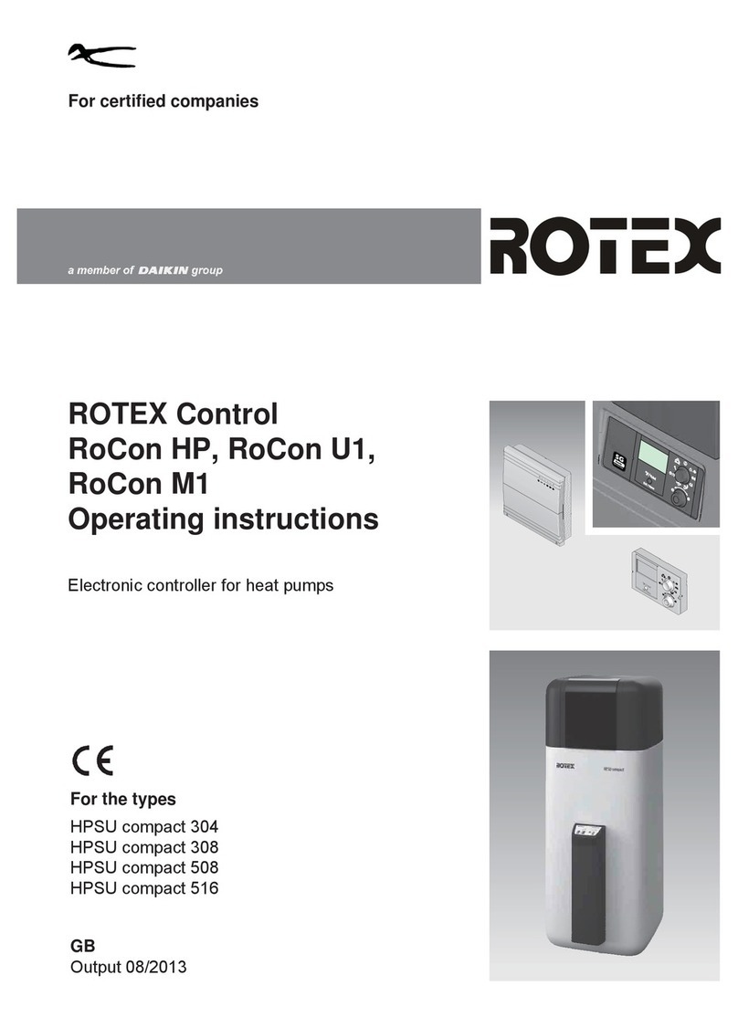
Rotex Controller Series Operator's manual

EbV Product documentation THETA NORM/UNIT
Product documentation
Controller series THETA
NORM, UNIT, RS and RFF types
Standing: Software version 2.3


EbV Product documentation THETA NORM/UNIT
I
1 Softwareversion ..................................................................................................... 1-1
2 General safety instructions .................................................................................... 2-1
2.1 Application .................................................................................................... 2-1
2.2 Conditions for start-up .................................................................................. 2-1
2.3 Safety measures for EMC - conform installation .......................................... 2-2
2.4 Cable dimensions and maximum cable length ............................................. 2-3
2.5 Maximum cable lengths ................................................................................ 2-4
2.6 Grounding and neutralizing ........................................................................... 2-4
2.7 Domestic hot water higher than 60 °C .......................................................... 2-4
2.8 Connecting accessories ................................................................................ 2-5
2.9 Service and cleaning .................................................................................... 2-5
3 Overview ............................................................................................................... 3-1
4 List of abbreviations .............................................................................................. 4-1
5 Operation .............................................................................................................. 5-1
5.1 User interface ............................................................................................... 5-1
5.1.1 Basic display .......................................................................................... 5-1
5.1.2 Operating elements ................................................................................ 5-2
5.1.2.1 Rotary Pushbutton (Press/Turn) ..................................................... 5-2
5.1.2.2 "Daytime Room Temperature" Key ................................................. 5-2
5.1.2.3 "Night-time Room Temperature" Key .............................................. 5-3
5.1.2.4 "Daytime DHW Temperature" Key .................................................. 5-3
5.1.2.5 "Operating Mode" Key (Basic Display) ............................................ 5-4
5.1.2.6 "Heating curve" key ....................................................................... 5-11
5.1.2.7 "Plant information" key .................................................................. 5-11
5.1.2.8 "Emission Measurement / Manual Mode" Key .............................. 5-15
5.2 Code-Input .................................................................................................. 5-17
5.2.1 Installer code and OEM code ............................................................... 5-17
5.2.2 User code ............................................................................................. 5-17
5.2.3 Automatic exit time ............................................................................... 5-18
5.3 Automatic return time .................................................................................. 5-19
5.4 Menu selection level ................................................................................... 5-20
5.4.1 Level and Parameter overview ............................................................ 5-21
5.4.2 "Time - Date" Menu .............................................................................. 5-23
5.4.3 "Time program" menu .......................................................................... 5-24
5.4.3.1 Control Circuit Selection ................................................................ 5-24
5.4.3.2 Program Selection ......................................................................... 5-24
5.4.3.3 Weekday and Cycle Selection ...................................................... 5-24
5.4.3.4 Programming Time Programs and Cycle Temperatures ............... 5-25
5.4.4 SYSTEM level (Parameter) .................................................................. 5-32
5.4.4.1 LANGUAGE .................................................................................. 5-32
5.4.4.2 Time programs .............................................................................. 5-32
5.4.4.3 Control mode ................................................................................. 5-33
5.4.4.4 Summer switch-off ........................................................................ 5-35
5.4.4.5 Reset Parameter ........................................................................... 5-35
5.4.5 DHW level ............................................................................................ 5-35
5.4.5.1 Hot water economy temperature ................................................... 5-35
5.4.5.2 Legionella protection day .............................................................. 5-36
5.4.6 Unmixed Circuit / Mixed Circuit 1 / Mixed Circuit 2 Menu .................... 5-36
5.4.6.1 Reduced Mode .............................................................................. 5-37
5.4.6.2 Heating system ............................................................................. 5-38
5.5 Malfunction messages ................................................................................ 5-39
5.6 Parameter Settings ..................................................................................... 5-40

EbV Product documentation THETA NORM/UNIT
II
5.6.1 HYDRAULIC Level ............................................................................. 5-40
5.6.2 SYSTEM level ..................................................................................... 5-42
5.6.3 DOMESTIC HOT WATER (Type ..B..) Level ....................................... 5-43
5.6.4 Selection levels unmixed circuit / mixed circuit 1 / mixed circuit 2 ....... 5-44
5.6.5 Heat generator level (..2..) ................................................................... 5-45
5.6.6 Raising Return Temperature Level ...................................................... 5-46
5.6.7 Solar Level (..VV..) ............................................................................. 5-46
5.6.8 Solid Fuel Level (..VV..) ...................................................................... 5-47
5.6.9 Buffer Level (..VV..) ............................................................................ 5-47
5.6.10 CASCADE CONTROL Level .............................................................. 5-48
5.6.11 BUS Level ........................................................................................... 5-48
5.6.12 RELAY TEST Level ............................................................................. 5-49
5.6.13 ALARM Level ....................................................................................... 5-49
5.6.14 Level SENSOR ADJ. .......................................................................... 5-49
6 General functions .................................................................................................. 6-1
6.1 Starting up .................................................................................................... 6-1
6.2 Controller configuration ................................................................................ 6-2
6.2.1 Complete reset ...................................................................................... 6-2
6.2.2 Basic settings and parameter preselection ............................................ 6-2
6.2.2.1 Switching Time Program Enabling .................................................. 6-2
6.2.2.2 Suppressing the cycle temperature on Time program level ........... 6-2
6.2.2.3 Eanbling separate operating modes and temperature changes ..... 6-3
6.2.2.4 Selection of Hydraulic Parameter Presettings (..F..) ....................... 6-3
6.2.2.5 Variable adaptation of hydraulic parameters
(variable inputs and outputs) .......................................................... 6-4
6.2.2.6 Temperature display in Fahrenheit ................................................. 6-6
6.2.2.7 Controller type code ........................................................................ 6-6
7 General controller functions .................................................................................. 7-1
7.1 Outside Temperature Measurement ............................................................ 7-1
7.1.1 Determination of long-time value and mean value ................................ 7-1
7.1.2 Building type .......................................................................................... 7-1
7.1.3 Heating Circuit Outside Temperature Assignment (Outdoor Sensor 2) 7-2
7.1.4 Alternative connection of the outdoor sensor to the boiler control (..C..) 7-2
7.1.5 Error display outdoor sensor during MCBA operation ........................... 7-2
7.1.6 Evaluation of the sensor errors MCBA .................................................. 7-2
7.2 Climate zone ................................................................................................ 7-3
7.3 Summer switch-off ........................................................................................ 7-3
7.4 System Frost Protection ............................................................................... 7-4
7.5 Pump and mix valve forced operation (Anti-blocking protection) ................. 7-6
8 Hydraulic components and their functions ............................................................ 8-1
8.1 Heat Generator: Boiler ................................................................................. 8-1
8.1.1 Heat Generator Start-up Protection (..2.., ..22.., ..C..) ........................... 8-1
8.1.2 Heat Generator Minimum Temperature Limit (..2.., ..22.., ..C..) ............ 8-2
8.1.3 Heat circuits minimum temperature limit ............................................... 8-2
8.1.4 Heat Generator Maximum Temperature Limit (..2.., ..22.., ..C..) ........... 8-3
8.1.5 Heat Generator Sensor Mode (..2.., ..22..) ............................................ 8-3
8.1.6 Minimum Burner Run Time (..2.., ..22..) ................................................ 8-4
8.1.7 Multi-stage Heat Generators/ Switching Differential (..2.., ..22..) .......... 8-4
8.1.8 Switching for modulating burners .......................................................... 8-7
8.1.8.1 Modulation P-band (Xp) .................................................................. 8-8
8.1.8.2 Modulation sample time Ta ............................................................. 8-8
8.1.8.3 Modulation integral action time Tn .................................................. 8-8

EbV Product documentation THETA NORM/UNIT
III
8.1.8.4 Modulation running time .................................................................. 8-8
8.1.8.5 Modulation starting time .................................................................. 8-9
8.1.8.6 Modulation starting load .................................................................. 8-9
8.1.9 Control of communicating heat generators (H-GEN type 5) ................ 8-10
8.1.10 Flue Gas Temperature Monitoring ....................................................... 8-10
8.1.11 Charging pump (CHP) ......................................................................... 8-11
8.1.12 Primary pump (PP) .............................................................................. 8-12
8.1.13 Boiler circuit pump ............................................................................... 8-12
8.1.14 Parallel heat generator release (PHR) ................................................. 8-13
8.1.15 Return control ...................................................................................... 8-13
8.1.15.1 Bypass pump (..VV..) .................................................................... 8-14
8.1.15.2 Return control through controlled flow mixing (..3..) ...................... 8-14
8.1.15.3 Indirect return control .................................................................... 8-15
8.1.16 When to activate boiler sensor 2 .......................................................... 8-15
8.1.17 External heat generator disable ........................................................... 8-16
8.1.18 Adjustment of the heat generator according to the common flow
temperature .......................................................................................... 8-16
8.1.19 Features of fuel value heat generator via data bus (MCBA) (..C..) ...... 8-16
8.1.19.1 DHW charging in boiler control MCBA .......................................... 8-16
8.1.19.2 DHW operation in combined devices ............................................ 8-17
8.1.20 Heat generator forced dissipation ........................................................ 8-18
8.1.21 Operating hours counter ...................................................................... 8-19
8.2 Heating circuit ............................................................................................. 8-19
8.2.1 Weather controlled heating operation .................................................. 8-19
8.2.1.1 Heating Characteristic Curve ........................................................ 8-19
8.2.1.2 Heating Circuit Reduced Mode ..................................................... 8-21
8.2.1.3 Heating system (exponent) ........................................................... 8-22
8.2.1.4 Heating Circuit Temperature Limitation ......................................... 8-22
8.2.1.5 Heating Circuit Parallel Shift ......................................................... 8-23
8.2.1.6 Heating circuit pump extended running time ................................. 8-23
8.2.1.7 Screed function ............................................................................. 8-24
8.2.2 Assessment of the Room Temperature / Room Influence ................... 8-26
8.2.2.1 Heating Circuit with Room influence ............................................. 8-26
8.2.2.2 Room factor heating circuit ........................................................... 8-27
8.2.2.3 Room Controller Heating Circuit ................................................... 8-28
8.2.2.4 Heating curve adaptation heating circuit ....................................... 8-28
8.2.2.5 Heating Circuit Room Frost Protection Limit ................................. 8-29
8.2.2.6 Room Thermostat Function (Room Temperature
Maximum Limit) ............................................................................. 8-29
8.2.2.7 Heating Circuit Switch-on Optimisation ......................................... 8-30
8.2.2.8 Optimisation for room controller (RC) ........................................... 8-31
8.2.3 Mixer control ........................................................................................ 8-31
8.2.3.1 Proportional band Xp .................................................................... 8-31
8.2.3.2 Integral action time Tn ................................................................... 8-31
8.2.3.3 Sample time Ta ............................................................................. 8-32
8.2.3.4 Actuator Running Time ................................................................. 8-32
8.2.4 Function Heating Limit ......................................................................... 8-34
8.3 Domestic hot water control (..B..) ............................................................... 8-34
8.3.1 DHW Tank Loading (DHW) .................................................................. 8-34
8.3.2 Circulation pump (CIR.) ....................................................................... 8-39
8.3.3 Electrical Heating Element (ELH) ........................................................ 8-40
8.4 Solar function (..VV..) .................................................................................. 8-40

EbV Product documentation THETA NORM/UNIT
IV
8.5 Function Buffer Loading Pump (..VV..) ....................................................... 8-43
8.6 Solid Fuel Loading Pump (SFP) ................................................................. 8-51
8.7 Tank charge changeover ............................................................................ 8-53
8.8 Heat forced dissipation valve ..................................................................... 8-54
8.9 Hydraulic buffer release (HBR) (..VV..) ...................................................... 8-55
8.10 Heating Circuit Constant Temperature Control (..2.. or ..3..) ...................... 8-56
8.11 Fixed Value Control (..2.. or ..3..) ............................................................... 8-56
8.12 Demand contact ......................................................................................... 8-57
8.13 Global Malfunction Message Output .......................................................... 8-58
8.14 Global Malfunction Message Input ............................................................. 8-58
8.15 Timer .......................................................................................................... 8-58
8.16 External switching modem ......................................................................... 8-59
8.17 External information ................................................................................... 8-60
9 Data bus / Bus Communication / Room controllers .............................................. 9-1
9.1 The data bus system .................................................................................... 9-1
9.1.1 Data bus addresses ............................................................................... 9-1
9.1.2 Control functions via the bus ................................................................. 9-2
9.1.2.1 Boiler corrosion protection .............................................................. 9-2
9.1.2.2 Indirect return temperature control ................................................. 9-2
9.1.2.3 Accumulator mode (accumulator priority mode) ............................. 9-2
9.1.2.4 Heating demand ............................................................................. 9-2
9.1.2.5 Clock synchronisation ..................................................................... 9-2
9.1.2.6 Room temperature information ....................................................... 9-2
9.1.2.7 Errors/ status indications ................................................................ 9-2
9.2 Operation of wall devices ............................................................................. 9-3
9.2.1 Operation of wall devices RS ................................................................ 9-3
9.2.2 Operation with wall device RFF ............................................................. 9-4
9.2.3 Bus priority heating circuit ..................................................................... 9-6
9.3 Expanding the system by several standard units ......................................... 9-7
9.3.1 Examples with several controllers ......................................................... 9-7
9.4 Unrestricted use of Gateway GWK .............................................................. 9-8
10 Cascading of heat generators in the bus system ................................................ 10-1
10.1 General description of cascading of control devices .................................. 10-1
10.2 Functions of the cascade parameter .......................................................... 10-1
10.3 Mode of operation of cascade control ........................................................ 10-3
10.3.1 Switch-on characteristics ..................................................................... 10-3
10.3.2 Switch-off behavior .............................................................................. 10-4
10.3.3 Operation with boiler control (old) ........................................................ 10-4
10.3.4 Operation with conventional heat generators (2-point) ........................ 10-4
10.3.5 Operation with boiler control (new) ...................................................... 10-5
10.3.6 Operation with group reversal ............................................................. 10-7
10.3.7 Behavior during heat generator fault ................................................... 10-8
10.3.8 Behavior for special functions .............................................................. 10-8
11 Help for commissioning, maintenance and problem solving ............................... 11-1
11.1 Automatic Set-Function .............................................................................. 11-1
11.2 Check safety temperature limiter ................................................................ 11-2
11.3 Relay / Function Test ................................................................................. 11-3
11.4 Malfunction messages ................................................................................ 11-4
11.4.1 Error messages basic display / Error stack ......................................... 11-6
11.4.2 OEM-Information for troubleshooting .................................................. 11-7
11.4.2.1 Controller complete reset .............................................................. 11-7
11.4.2.2 Controller time correction .............................................................. 11-7

EbV Product documentation THETA NORM/UNIT
V
11.5 Sensor Calibration ...................................................................................... 11-7
12 Mounting ............................................................................................................. 12-1
12.1 Mounting instructions for NORM type ......................................................... 12-1
12.1.1 Electrical installation ............................................................................ 12-1
12.1.2 Electrical installation ............................................................................ 12-2
12.2 Mounting instructions for UNIT type ........................................................... 12-3
12.2.1 Mounting UNIT ..................................................................................... 12-3
12.2.2 Electrical installation ............................................................................ 12-4
12.2.3 Electrical connection ............................................................................ 12-5
12.3 Mounting instructions for mounting with wall socket MS-K ......................... 12-6
12.3.1 Electrical installation ............................................................................ 12-6
12.3.2 Electrical connection in wall socket MS-K ............................................ 12-8
12.4 Mounting instructions remote unit ............................................................... 12-9
12.4.1 Mounting location ................................................................................. 12-9
12.4.2 Electrical connection .......................................................................... 12-10
12.4.3 Data bus addressing .......................................................................... 12-10
12.5 Mounting instructions wall device RFF ..................................................... 12-11
13 Accessories ......................................................................................................... 13-1
13.1 Outdoor sensor AF ..................................................................................... 13-1
13.2 Immersion sensor KVT ............................................................................... 13-2
13.3 Flow sensor VF ........................................................................................... 13-3
13.4 Flue gas sensor / solar panel flow sensor .................................................. 13-4
14 Technical Data .................................................................................................... 14-1
14.1 General ....................................................................................................... 14-1
14.2 Technical data for sensor and digital inputs ............................................... 14-2
14.2.1 Sensor Resistance Values ................................................................... 14-2
14.2.2 Sensor measuring ranges .................................................................... 14-2
14.2.3 Digital inputs ........................................................................................ 14-2
15 Index ................................................................................................................... 15-1

EbV Product documentation THETA NORM/UNIT
VI

EbV Product documentation THETA NORM/UNIT
1-1
1 Softwareversion
Please use this documentation in conjunction with softwareversion V 2.3 of your controller. The version will
be displayed for about 8 s when the controller is connected to the mains. If you are using an older version,
please contact your heating specialist.

EbV Product documentation THETA NORM/UNIT
1-2

EbV Product documentation THETA NORM/UNIT
2-1
2 General safety instructions
2.1 Application
The controller family THETA is designed exclusively for the control of warm water heating and district
heating systems including domestic hot water control. These systems should not exceed a flow temperature
of 120 °C.
2.2 Conditions for start-up
CAUTION The heating installation must be completed and filled with water in order to prevent
the pumps from running dry and to avoid damage of the boiler.
CAUTION Switch off plant completely before opening boiler control panel! Do not plug or unplug
electrical connectors under voltage. This may damage the controller or cause
dangerous electrical shock.
The controller must be installed according to the installation instructions.
All electrical connections and safety measures have to be carried out by a specialist
according to the valid norms and VDE-guidelines as well as the local instructions.
The electrical connection must be fix (see instructions by VDE 0100).
The electrical connection has to be done according to the wiring diagram of the
respective boiler control panel.
If a floor heating system is connected, a limiting thermostat must switch off the pump
if the flow temperatures are too high.
The heating specialist must check all the above mentioned requirements before
switching on the controller.
IMPORTANT NOTE! The current time and date are already set by the factory and backed up by a battery.
The timer has a basic time program already activated and the control functions for
standard heating systems with low temperature boilers are pre-adjusted.
If this happens the backup battery will be stressed unnecessarily. Also the frost
protection functions of the controller will be shut down.
All electrical connections must be carried out by qualified personnel.

EbV Product documentation THETA NORM/UNIT
2-2
2.3 Safety measures for EMC - conform installation
• Cables with mains voltage must generally be installed separately from sensor and data bus cables. In
this case a minimum distance of 2 cm between the cables must be observed. Crossing of lines is
permitted.
• Controls with own mains connections require a separate installation of mains and sensor or data bus
cable. When using cable ducts, types with internal separators are recommended.
• When installing control or remote units close to other components with electro magnetic emission such
as solid state relays, motors, transformers, dimmers, micro wave ovens, TV-sets, loudspeakers,
computers, radio telephones etc. a minimum distance of 40 cm must be observed.
• Between remote units and standard units, a minimum distance of 40 cm has to be observed. Several
standard units in a data bus connection may be installed side by side.
• The mains connection of the heating plant (standard unit or boiler control panel) must be carried out as
an independent electric circuit. It is not permitted to install fluorescent tubes or other machines that could
produce interferences to the same electrical circuit.
Mains 230 V~
15 cm
2 cm
Data bus line 12V~
Fig. 1
40 cm
Fig. 2
Install fluorescent tubes
and plugs
on separated circuits.
Fuse 16 A
Emergency-switch
Remote
unit(s)
Heat generator
Fig. 3

EbV Product documentation THETA NORM/UNIT
2-3
• All data bus cables must be carried out in shielded version.
Suggested version, see technical specifications on page 14-1
• The shielding of the cable has to be connected with earth potential to one side, i.e. boiler covering,
connecting terminals for earth potential etc. Multiple grounding is not permitted (humming loop).
• In star shaped networks it is not permitted to ground cables on both sides. They should be grounded in
the centre.
• The outside sensor may not be installed close to transmitter- or receiver-equipment (on garage walls
close to receivers for radio-controlled garage door openers, ham operator antennas, radio controlled
alert systems or close to big radio transmission plants).
2.4 Cable dimensions and maximum cable length
• For all 230V~ cables such as power supply, burner, pumps, actuators: 1,5 mm2
Maximum cable length:
Unlimited cable length within house installation.
• Data bus connections: 0.6 mm2
Recommended cables:
J-Y(St)Y 2 x 2 x 0.6 mm2
Maximum cable length: 50 m
Longer distances should be avoided to decrease the risk of interferences.
• For all low voltage cables such as sensors, extern selectors, bus and analogue in- and outputs, heat
requiring by means of extern contact, modem connection cables, etc.: 0.5 mm2
Maximum cable length: 50 m
Longer distances should be avoided to decrease the risk of interferences.
Fig. 4: Single grounding of shielding
Do not ground here!
Heat generator
PE
Shielding
2-wire
data bus line
Distribution terminal
Distribution box
PE
Fig. 5

EbV Product documentation THETA NORM/UNIT
2-4
2.5 Maximum cable lengths
Sensor, selector and analogue inputs
• A maximum cable length of 100 m is recommended. Longer cables are possible but increase the risk of
interferences.
Relay outputs
• Unlimited cable length.
Bus lines
• Maximum length 50 m
2.6 Grounding and neutralizing
• Always observe local guidelines when installing the devices!
2.7 Domestic hot water higher than 60 °C
Please note that in the following cases there is a danger of scalding due to hot water taps (kitchen, bath).
In order to avoid scalding please mix enough cold water.
Anti legionella automatic
If the anti legionella automatic is activated, the domestic hot water will automatically be heated up to a
temperature of 65 °C in order to kill legionella bacteria in the hot water system on the selected day and at
the selected time.
Manual operation / Emission measurement
In the manual mode / emission measurement mode the domestic hot water can be heated up to the
maximum possible boiler temperature because the burner and all pumps are switched on and the valves
will be completely opened. In this case, there is the danger of scalding at all connected warm water taps in
the building. Please mix enough cold water or switch the domestic hot water loading pump off manually (if
there is a switch at the pump). Heating and domestic hot water are not temperature controlled in these
modes. These modes are especially used by the emission measurement specialist or by the installer in case
the controller is defective. However, the high water temperatures can be avoided if the boiler thermostat is
adjusted to a max. boiler tmepertaure of 60 °C.

EbV Product documentation THETA NORM/UNIT
2-5
2.8 Connecting accessories
WARNING According to VDE 0730 the power supply for the controller must have a separate
main switch for life and neutral. Please observe local guidelines for grounding and
neutralizing!
As soon as there is power supply at the terminals 21, 22, 2, 6, 12 and 18 also the
terminal rows X3 and X4 will carry 230 V connections!
If a manual switch function is desired for pumps, even though the DHW charging
pump does not have on/off switches, external switches must be installed. All
accessories (sensors, selectors, etc.) must be connected according to the attached
wiring diagram.
2.9 Service and cleaning
The controller is service free. The unit can be cleaned on the outside with a moist (not dripping) cloth.

EbV Product documentation THETA NORM/UNIT
2-6

EbV Product documentation THETA NORM/UNIT
3-1
3Overview
If the described function is practicable in combination with the controller type, can be seen in the type key.
The description refers to this key. Example: In the description, it says: "(Type ..VV..)". This means that this
function is implemented in controller types that have the designation "VV" in the type key. The following
types can be selected:
Type
2. Burner stage
1. Burner stage
Direct circuit (HC)
MC 1
MC 2
Domestic hot water charging pump
Variable outputs 1+2
H-GEN-bus RS 485
HG-bus OpenTherm
Variable input 1
Variable input 2+3
Inputs for solar
2B X X X X
23B X X X X X
233B XXXXX X
2233BVV XXXXXXX XXX
23BC X X X X X X
23BVVC-OT XXX XX XXXX
233BVVC XXXXXXX XXX
2233BVVC XXXXXXXX XXX
2233BVVC-OT XXXXXXX XXXX
3 X X

EbV Product documentation THETA NORM/UNIT
3-2

EbV Product documentation THETA NORM/UNIT
4-1
4 List of abbreviations
BCP Boiler circuit pump OS 2 Outdoor sensor 2
BOSF Boiler sensor (solid fuel) OT Outside temperature
BU Buffer sensor (top) P1 Time program
BU 2 Buffer sensor 2 (bottom) P2 Time program
BULP Buffer charging pump P3 Time program
BURN1 Burner stage 1 PHR Parallel H-GEN clearance
BURN2 Burner stage 2 PIN Pulse input
BUS System databus (T2B) RBP Return bypass pump
BUSF Buffer sensor (solid fuel) RED Reduced mode
CC Constant control RP Return pump
CHP Feed pump RS Return flow sensor
CIR. DHW circulation pump RU Remote unit for room
temperature measurement
DHW Domestic hot water SD I Switching differential I
DHWS DHW sensor SD II Switching differential II
ECO Eco mode SFP Solid fuel pump
ELH DHW electrical heating
element SLV Solar load switch
EM Extra Module SOL-P DHW charging pump
FGS Flue gas sensor SOP Solar charging pump
FSC Fixed set-point control SPBU Solar panel /
buffer sensor
HC Direct circuit SPFS Solar panel flow sensor
HC Heating circuit (general) SPRS Solar panel return sensor
HC-P Pump for direct heating circuit SSLS Sensor solar load switch
HG-BUS Heat generator-data bus
(RS485) SZV Solar forced discharge
H-GEN Heat generator VF1 Flow sensor MC1
H-GENS/BS Boiler sensor VF2 Flow sensor MC2
MC Mixing circuit VI Variable input (general)
MCP Mixing circuit pump VI1 Variable input 1
MIMO Mixer motor VI2 Variable input 2
OHC1 Operat. hours counter
Burner stage 1 VI3 Variable input 3
OHC2 Operat. hours counter
Burner stage 2 VO Variable output
OS Outdoor sensor

EbV Product documentation THETA NORM/UNIT
4-2
This manual suits for next models
4
Table of contents
Other Rotex Controllers manuals
Popular Controllers manuals by other brands

FASTRON.
FASTRON. Meridian MEC-110 operating instructions

Sol
Sol SolCon-016 Operation manual

LOVATO ELECTRIC
LOVATO ELECTRIC ATL600 instruction manual

Honeywell
Honeywell T775R 2000 Series installation instructions

HTW
HTW HTW-KJR86A1E Installation and operation manual

Honeywell
Honeywell HCE 60 Installation and operation