metso automation ND800PA Operating and maintenance manual

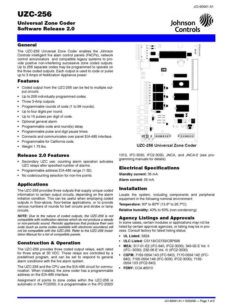
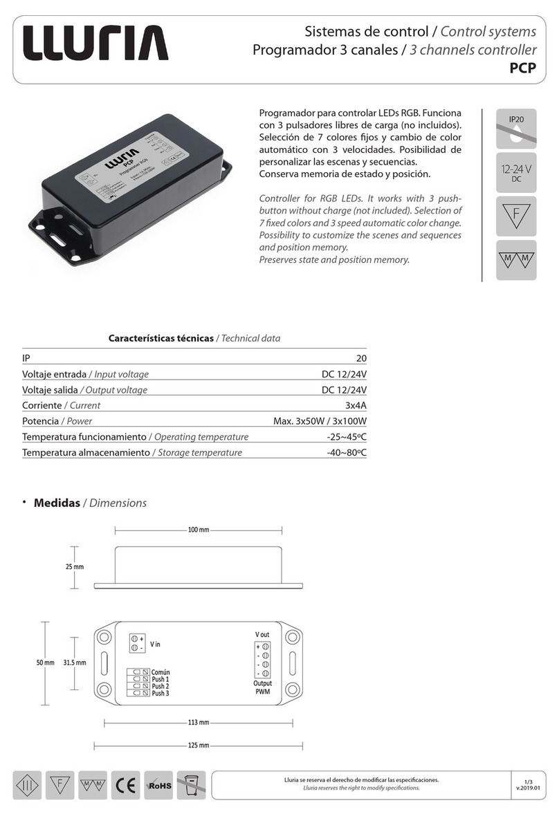
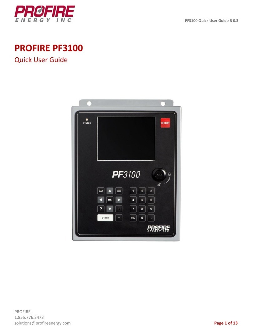
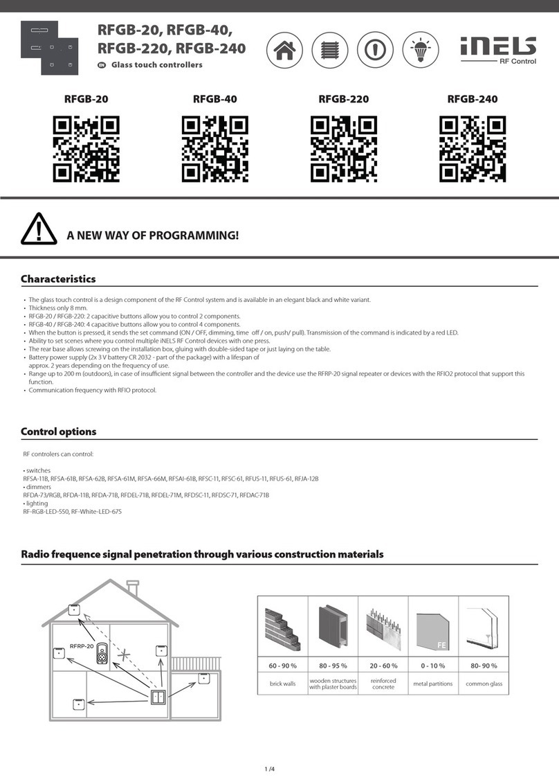
VALVE CONTROLLER
ND800PA
Rev. 1.0
Installation, Maintenance and
Operating Instructions
7 ND 72 en
4/2001

Table of Contents
1 INTRODUCTION . . . . . . . . . . . . . . . . . . . . . 3
1.1 General . . . . . . . . . . . . . . . . . . . . . . . . . . . . . . . . 3
1.2 Principle of operation . . . . . . . . . . . . . . . . . . . . 3
1.3 Markings . . . . . . . . . . . . . . . . . . . . . . . . . . . . . . . 3
1.4 Technical specifications . . . . . . . . . . . . . . . . . . . 3
1.5 Safety precautions . . . . . . . . . . . . . . . . . . . . . . . 5
2 MOUNTING . . . . . . . . . . . . . . . . . . . . . . . . . 5
2.1 General . . . . . . . . . . . . . . . . . . . . . . . . . . . . . . . . 5
2.2 Mounting on Metso Automation actuators
with VDI/VDE mounting face (S1) . . . . . . . . . 5
2.3 Mounting on Metso Automation actuators
with old mounting face (S2). . . . . . . . . . . . . . . 5
2.4 Mounting on linear actuators withMetso
Automation or IEC 60534 mounting face . . . 6
2.5 Piping of supply air. . . . . . . . . . . . . . . . . . . . . . . 7
2.6 Electrical connections . . . . . . . . . . . . . . . . . . . . 7
3 USER INTERFACE . . . . . . . . . . . . . . . . . . . . 9
3.1 Keyboard and display . . . . . . . . . . . . . . . . . . . . 9
3.2 Keyboard functions . . . . . . . . . . . . . . . . . . . . . . 9
3.3 HW write protection . . . . . . . . . . . . . . . . . . . . 9
4 CONFIGURATION. . . . . . . . . . . . . . . . . . . 11
4.1 Zero and range . . . . . . . . . . . . . . . . . . . . . . . . 11
4.2 Position control . . . . . . . . . . . . . . . . . . . . . . . . 11
4.3 Control valve related settings. . . . . . . . . . . . . 12
5 MAINTENANCE . . . . . . . . . . . . . . . . . . . . . 13
5.1 Prestage. . . . . . . . . . . . . . . . . . . . . . . . . . . . . . . 13
5.2 Spool valve . . . . . . . . . . . . . . . . . . . . . . . . . . . . 14
5.3 Circuit board pack . . . . . . . . . . . . . . . . . . . . . . 14
5.4 Position sensor. . . . . . . . . . . . . . . . . . . . . . . . . 15
5.5 Pressure sensor . . . . . . . . . . . . . . . . . . . . . . . . 15
6 ERROR MESSAGES. . . . . . . . . . . . . . . . . . . 16
7 TROUBLE SHOOTING . . . . . . . . . . . . . . . 17
8 TOOLS . . . . . . . . . . . . . . . . . . . . . . . . . . . . . 17
9 ORDERING SPARE PARTS . . . . . . . . . . . . 17
10 ND800/K00 (WITH LIMIT SWITCHES) . 18
10.1 Introduction. . . . . . . . . . . . . . . . . . . . . . . . . . . . 18
10.1.1 General description . . . . . . . . . 18
10.1.2 Markings . . . . . . . . . . . . . . . 18
10.1.3 Technical specifications . . . . . . . 18
10.1.4 Safety precautions . . . . . . . . . . 18
10.2 Installing ND800/K00 on a valve controller . 19
10.3 Electrical connections. . . . . . . . . . . . . . . . . . . . 19
10.4 Adjustment . . . . . . . . . . . . . . . . . . . . . . . . . . . . 19
10.5 Removal of the limit switch ND800/K00
for accessing the valve controller . . . . . . . . . . 19
10.6 Circuit diagrams . . . . . . . . . . . . . . . . . . . . . . . . 19
10.7 Maintenance . . . . . . . . . . . . . . . . . . . . . . . . . . . 19
10.8 Ordering spare parts . . . . . . . . . . . . . . . . . . . . 19
11 DRAWINGS AND PARTS LISTS . . . . . . . 20
11.1 Exploded view and parts list . . . . . . . . . . . . . . 20
11.2 Mounting parts for B1C/B1J 6-20 actuators . 21
11.3 Mounting parts for B1C/B1J 25-50,
B1C 502 and B1J322 actuators. . . . . . . . . . . . 21
11.4 Mounting parts for Quadra-Powr®, ST,
SP and Valv-Powr®actuators. . . . . . . . . . . . . 22
11.5 Mounting parts for D/R linear actuators . . . . 23
11.6 Mounting parts for linear actuators
with IEC 60534 mounting face . . . . . . . . . . . . 24
11.7 Connections . . . . . . . . . . . . . . . . . . . . . . . . . . . 25
11.7.1 Connection diagram for ND800/K05
and ND800/K06 . . . . . . . . . . . 25
11.7.2 Device gland receptacles . . . . . . 26
12 DIMENSIONS . . . . . . . . . . . . . . . . . . . . . . . 27
12.1 ND800/K00. . . . . . . . . . . . . . . . . . . . . . . . . . . . 28
13 TYPE CODING . . . . . . . . . . . . . . . . . . . . . . 29
READ THESE INSTRUCTIONS FIRST!
These instructions provide information about safe handling and operation of the valve controller
If you require additional assistance, please contact the manufacturer or manufacturer’s representative.
Addresses and phone numbers are printed on the back cover.
SAVE THESE INSTRUCTIONS!
Subject to change without notice.
All trademarks are property of their respective owners.
2

1INTRODUCTION
1.1 General
These instructions describe the digital Metso Automation
ND800PA valve position controller. The ND800PA can be used
with either cylinder or diaphragm type pneumatic actuators for
rotary or linear valves.
1.2 Principle of operation
The ND800PA is a fieldbus powered microcontroller-based valve
controller. The ND800PA configuration can be done either using
local push buttons, Simatic PDM (Process Device Manager) or some
other suitable Profibus PA configurator.
Using push buttons or PDM the configuration parameters can be
set according to the actuator and valve in question. Then auto-cali-
bration can be started via push buttons or PDM.A three-digit display
with text labels describes the operation.
In control service the microcontroller (µC) reads data from the input
signal (Profibus PA), position sensor (α) and pressure sensor (p). A
change in input signal will be detected by control algorithm inside
the µC. The microcontroller will change the pilot current to one of
the prestage (PR) coils. A prestage valve lowers the pilot pressure
at the end of the spool valve (SV). The spool moves in the direction
of low pressure to open the flow in to the top of the actuator
cylinder and out from the other side of the piston. The increasing
pressure difference over the piston moves the piston and rotates
the feedback shaft. A position sensor ( a) measures the rotation for
the µC. Using a control algorithm the microcontroller adjusts the
pilot current until a new position of the actuator proportional to the
input signal is reached. In the steady state, the spool valve (SV) and
prestage (PR) valves are closed.
1.3 Markings
The valve controller is equipped with an identification plate
sticker (Fig. 2). Identification plate markings from top to bottom are:
Type designation of the valve controller
Revision number
Enclosure class
Input signal
Maximum supply voltage
Supply pressure range
Operational temperature
Manufacturing series number
CE mark
Alternative markings on the optional plate (Fig. 3):
Filter-regulator (-K)
Operational temperature of regulator
Conduit entries (-L, -I or -NJ)
1.4 Technical specifications
General
The ND800PA valve controller is suitable for rotary and slid-
ing stem valves.
Actuator connection In accordance with VDI/VDE 3845
standard (S1) or as an option
compatibility with other NE-series (S2).
To replace an existing NE/NP positioner,
specify existing valve assembly
Action: Double or single acting
Turning angle: min 45°, max 95°
Environmental influence
Operational temp.: -20 - +85 °C (-4 - +185 °F)
option -40 - +85 °C (-40 - +185 °F)
Influence of temperature on valve position
< 0.05%/°C
Influence of vibration on valve position
< 1% under 2g 5-150 Hz and
1g 150-300 Hz
0.5g 300-2000 Hz
C
SV
C2
C1
PR
Profibus PA
14
3
2
P
α
µ
S
Fig. 1. Schematic diagram
Fig. 2. Identification plate
Fig. 3. Optional plate
3

Enclosure
Material: Anodized aluminium alloy
Protection class: IP65, NEMA 4 and 4X
Mechanical position
indicator: on cover
Pneumatics ports: 1/4 NPT
Electrical connection: Screw terminals internals for 2.5 mm2
and 1 PG 13.5 conduit entry
(1/2 NPT, M20x1.5 and R 1/2 as option,
see optional plate)
Weight: 2.1 kg (4.6 lbs)
Pneumatics
Supply pressure: 2.5-8 bar (36-115 psi)
Effect of supply
pressure: < 0.2 %/10 kPa (0.14%/psi)
Air quality: As defined by ISA S7.3 standard
Capacity: Max 30 Nm3/h (18 scfm)
at 4 bar (60 psi) supply
Consumption: 0.4 Nm3/h (0.24 scfm)
at 4 bar (60 psi) supply
Electronics
Power supply: Taken from bus
Bus voltage: 9 to 32 VDC
Reverse polarity protection permits
connection of the bus cables in any order
Power consumption: 23 mA
Electronic current limitation:
Imax ≤24 mA in case of fault
Performance with moderate constant load actuators
Hysteresis + dead band:< 1 %
Linearity error: < 2%
Local keypad functions
Calibration: Automatic / Manual
Control feedback: 0.0-3.0 (d and b)
Gain configuration: 0.1-3.0 (gain)
Mode Selection: Auto/Man/Off
Positioner Fail Action, PFA:
- close (default)
- open
Position Sensor Rotation, ROT:
- clockwise (default)
- counterclockwise
Dead Angle Compensation, A0:
acc. to valve (0 % default)
Valve Type Selection, TYP:
- rot (rotary valve), default
- lin (linear valve)
Setpoint Cut-off CLOSE, CLO:
- 0-100 % (2 % default)
Setpoint Cut-off OPEN, CHI:
- 0-100 % (100 % default)
Lower Limit Valve Position, RLO:
- 0-100 % (0 % default)
Upper Limit Valve Position, RHI:
- 0-100 % (100 % default)
Profibus slave address, ADR:
- 0-126, default 126
Electrical connections
Input signal: Profibus PA
according to IEC 61158-2
Approvals
Temp. ≤ +75 °C (+67 °F):
Cenelec EEx ia IIC T5/T6 (pending),
Temp. ≤+50 °C (+122 °F):
CSA Class I, Division 2, Groups A, B, C
and D (pending)
Sensors
Position sensor
linear range: 110 °
Actuator pressure
sensor linear range: 7 bar (100 psi) (differential pressure)
User interfaces
Local: 3 keys + LCD display
Simatic PDM functions:
Flow characterization: Linear, equal percentage, quick opening,
custom
Identification information:
HW/SW rev., serial numbers, actuator type etc.
Monitoring: Valve travel setpoint, actual travel,
actuator pressure and device temperature
Diagnostics: Travel deviation, travel duration, load factor,
operation time, valve/actuator travel counters,
failure information
Testing: Step response, hysteresis loop
Module calibration: Position sensor, pressure sensor, tempera-
ture measurement
Electromagnetic protection
Protection standards: EN50081-1 and EN50082-2
IEC 801-2 ESD, level 4,
IEC 801-3 Electro Magnetic Field, level 3
IEC 801-4 Fast Transients, level 4
CE marking
Electromagnetic
compatibility: 89/336/EEC
4

1.5 Safety precautions
CAUTION:
Do not exceed the permitted values!
Exceeding the permitted values marked on the valve control-
ler may cause damage to the controller and to equipment
attached to the controller and could lead to uncontrolled
pressure release in the worst case.
Damage to the equipment and personal injury may result.
CAUTION:
Do not remove or dismantle a pressurized controller!
Removing or dismantling a pressurized prestage, spool valve
or pressure sensor of an ND800PA leads to uncontrolled
pressure release. Always shut off the supply air and release
the pressure from the pipelines and equipment before re-
moving or dismantling the controller.
Otherwise personal injury and damage to equipment may result.
CAUTION:
During automatic or manual calibration the valve oper-
ates between open and closed positions. Make sure that
the operation does not endanger people or processes!
NOTE:
Avoid earthing a welding machine in close proximity to an
ND800PA valve controller.
Damage to the equipment may result.
NOTE:
The display may become unreadable in ambient temperatures
below -20 °C/-4 °F.
Warming up the display, for instance with thumb, may be
necessary in such conditions.
2MOUNTING
2.1 General
If the ND800PA is supplied with valve and actuator the tubes are
mounted and the ND800PA adjusted in accordance with the
customer’s specificatons. If the controller is ordered separately, the
mounting parts for the assembly must be ordered at the same time.
Sample order: (B1C13)-Z-ND826/S1.
The controller is equipped with both the new Metso Automation
mounting face, for connection according to VDI/VDE 3845 (S1),
and the old Metso Automation mounting face (S2).
Shaft alternatives for the controller for Metso Automation rotary
actuators are shown in Fig. 4.
For mounting parts for Metso Automation actuators, see Sections
10.2-10.6.
2.2 Mounting on Metso Automation actuators
with VDI/VDE mounting face (S1)
See Sections 10.2, 10.4
Run the actuator until the piston is in the top position
(spring return actuators in the position determined by the
spring).
Set the direction arrow in the direction of the valve closure
member and attach the draught piece (2) to the indicator
cover in the position shown in Fig. 4. Secure the screw of
the draught piece e.g. with Loctite and tighten it sufficiently.
Attach the bracket (1) to the ND800PA.
Attach the bracket (1) to the actuator. The shaft (40) of
the ND800PA must fit into the draught piece (2) shown
in Fig. 5. See also drawings in Section 10.2.
Note the differences in installation between the B1C, B1J and B1JA
actuators.
2.3 Mounting on Metso Automation actuators
with old mounting face (S2)
See Sections 10.2, 10.3
Run the actuator until the piston is in the top position (spring
return actuators in the position determined by the spring).
Set the direction arrow in the direction of the valve closure
member and attach the draught piece (2) to the indicator
cover in the position shown in Fig. 5. Secure the screw of
the draught piece e.g. with Loctite and tighten it sufficiently.
Attach the bracket (1) to the ND800PA.
Attach the bracket (1) to the actuator. The shaft (40) of
the ND800PA must fit into the draught piece (2) shown
in Fig. 5. See also drawings in Sections 10.2 and 10.3.
Note the differences in installation between the B1C, B1J and B1JA
actuators.
C2
S
C1
The mark on the shaft must
stay in this sector
Fig. 4. Mounting on Metso Automation actuator with
VDI/VDE mounting face
draught piece (2)
coupling
coupling
bracket (1)
bracket (1)
B1C, B1J
B1JA
Fig. 5. Mounting on Metso Automation actuator with old
mounting face
40
40
mark
Shaft alternatives
mark = yellow dot
S2
S1
5

2.4 Mounting on linear actuators withMetso
Automation or IEC 60534 mounting face
See Sections 10.5, 10.6.
Connect an airset directly to the actuator and position the
actuator at its mid-stroke position (see serial plate for
actuator stroke length).
Attach the feedback arm on to the controller input shaft.
Make sure the lettering on the feedback arm faces up,
toward the controller.
Attach the controller mounting bracket loosely on to the
slotted leg of the actuator. Make sure the marks on the
shaft and feedback arm operate in the quadrant shown.
Measure the distance from the centre of the feedback
lever shaft to the slot on the feedback lever and mark this
distance with a pencil or other marking instrument. Use
the dimensions given in Sections 10.5 and 10.6.
Mount the controller loosely onto the controller mounting
bracket.
Adjust the controller mounting bracket and the controller
so that the controller is at 90°to the centre line of the
actuator and the controller feedback lever is horizontal
and at 90°to the centre line of the actuator.
Tighten the controller mounting bracket screws.
Adjust the controller on the controller mounting bracket so
that the measured distance is maintained between the centre
of the feedback lever shaft and the actuator pin (pre-meas-
ured mark on the feedback lever). Note the controller must
still conform to the specifications in previous steps.
Tighten all the mounting bolts and then re-check that the
controller complies with previous steps. Check that the
actuator pin does not touch the controller case through-
out the entire stroke of the actuator. If the actuator pin is
too long it may be trimmed to length. (The pin must be
trimmed on stroke of 1.125" or less.)
Actuator Piping Spool
valve
Plastic/Cu/SS (") Plastic/Cu/SS (mm)
B1C Stroke vol.
dm3/in3NPT 1/4 3/8 1/2 6/4 10/8 12/10
6 0.3/18 1/4 x x 2
9 0.6/37 1/4 x x 2
11 1.1/67 3/8 x x 2
13 2.3/140 3/8 x x 6
17
20
4.3/262
5.4/330
1/2 x
x
x
x
6
6
25
32
10.5/610
21/1282
1/2
3/4
x
x
(x)
(x)
x
x
(x)
(x)
6
6
40
50
43/2624
84/5126
3/4
1
(x)
(x)
x
x
x
x
6
6
502 195/11900 1 x x 6
B1J
B1JA
Stroke vol.
dm3/in3NPT 1/4 3/8 1/2 6/4 10/8 12/10 Spool
valve
8
10
0.9/55
1.8/110
3/8 x
x
x
x
21
61
12
16
3.6/220
6.7/409
1/2 x
x
x
x
61
61
20
25
13/793
27/1648
3/4 x
x
(x)
(x)
x
x
(x)
(x)
61
61
32
322
53/3234
106/6468
1(x)x
x
x
x
61
61
QP Stroke vol.
dm3/in3NPT 1/4 3/8 1/2 6/4 10/8 12/10 Spool
valve
1 0.62/37 3/8 x x 21
2 1.08/66 3/8 x x 21
3 2.18/133 3/8 x x 61
4 4.34/265 3/8 x x 61
58.7/5313/8 x x 61
6 17.5/1068 3/4 x x 61
Table 1. Piping
6

Attach the spring on to the feedback arm as shown.
Apply grease (Molykote or equivalent) to the contact
surfaces of the actuator pin and the feedback lever to
reduce wear.
Increase and/or decrease air pressure to the actuator to
stroke the actuator full stroke to check that nothing is
binding and that the rotation of the feedback lever is 70°
for a 1"-5" stroke and 60°for a 3⁄4" stroke. See Sections
10.5 and 10.6.
2.5 Piping of supply air
CAUTION:
Do not exceed the permitted supply pressure
of the ND800PA!
Table 1 provides the recommended tube sizes in accordance with
actuator sizes. Tube sizes are the minimum values allowed. For
supply air choose a tube one size bigger. Operating times can be
tested by the PDM.
Connect the air supply to S (1/4 NPT).
Connect C1 and C2 (1/4 NPT) to the actuator.
For the pipe threads liquid sealants, such as Loctite 577, are
recommended.
NOTE:
Too much sealant may cause faulty operation of the controller.
Sealing tape is not recommended.
Ensure the cleaniness of the air piping.
The supply air must be clean, dry and oil-free instrument air, e.g.
according to standard ISA S7.3-81.
2.6 Electrical connections
The bus cable is led through a PG13,5 cable gland. Connect the
conductors to the terminal strip according to Fig. 6.
Reverse polarity protection permits connection of the bus cables in
any order.
Depending on the plant grounding policy, wheter Equipotential
Bonding or Capacitive grounding can be used. See "PROFIBUS - PA
User and Installation Guideline". In the case of Equipotential Bonding,
connect the cable shield to earth connection screw. In the case of
Capacitive grounding, connect the cable shield to terminal strip 1. "
Profibus PA
Earth connection
Fig. 6. Terminals
Actuator type Spring rate (bar/psi)
B1JK
B1JSTD
B1JV
QPB
QPC
QPD
3/43
4.2/61
5.5/80
3/43
4.3/62
5.6/81
Adjust regulator pressure to a level which is max 1 bar (14.5
psi) + spring rate. If spring rate is less than 3 bar (43 psi)
then supply pressure 4 bar (58 psi) is recommended.
Table 2. Spring rates
7

SINGLE-ACTING ACTUATOR (SPRINGTO OPEN)
SINGLE-ACTING ACTUATOR (SPRINGTO CLOSE)
DOUBLE-ACTING ACTUATOR
1. Self closing.
Default setting:
PFA = CLO
ROT = cC ( lose valve to lockwise)
A0 = % (acc. to valve type)
cLo = 2 %
c c
3. Self closing.
Spring to close valve.
Default setting:
PFA = CLO
ROT = cC ( lose valve to lockwise)
A0 = % (acc. to valve type)
cLo = 2 %
c c
5. Self opening.
Spring to open valve.
Setting:
PFA = OPE
ROT = cC ( lose valve to lockwise)
A0 = % (acc. to valve type)
cLo = 2 %
c c
4. Self opening
Spring to open valve.
Setting:
PFA = OPE
ROT = ccC ( lose valve to ounter lockwise)
A0 = % (acc. to valve type)
cLo = 2 %
c c c
CAUTION: Valve closes exceptionally counterclockwise.
Unsuitable for Q-, R-, T5-, F- and L-series valves.
2. Self opening.
Setting:
PFA = OPE
ROT = cC ( lose valve to lockwise)
A0 = % (acc. to valve type)
cLo = 2 %
c c
C1
C2
S
C1
C2
S
C1
C2
S
C1
C2
S
C1
C2
S
After self-tuning the default parameters are as follows: Gain = 1.0 (for enhanced control use Gain=1.2)
d = 0.0 for double acting actuators (factory set)
d = 1.0 for single acting actuators (factory set)
b=1.0
In order to achieve symmetrical operation, always use filter regulator in connection with spring return actuators. See Table 2.
RA and DA actuators: use spool 21A. RB, RC, RD, RE and DB, DC, DE actuators: use spool 61A.
NOTE: Use QP values for diapharagm-pneumatic linear actuators.
Use B1J values for spring-return cylinder actuators. Use B1C values for double-acting cylinder actuators
If operational conditions change considerably, perform self-tuning for optimum performance.
Fig. 7. Operation directions and air connections
8

3 USER INTERFACE
3.1 Keyboard and display
The keyboard and the display of the ND800PA are shown in Fig.
8. Only applicable information is shown on the display in each mode.
Operations and display are controlled by +, -and rkeys.
Four setting functions are available: m, g, dor
c. Each of these names refers to the function to be adjusted
or changed.
In aor Mmode the display indicates 0-100 % as the valve
travel. In omode the display shows two dashes (--) instead of
digits. By pressing the rkey the display shows the input signal in mA
within about 5 seconds. In other situations the display indicates the
adjustable parameter value selected.
3.2 Keyboard functions
See keyboard operations (Fig. 11).
The keyboard setting state is initiated by pressing the +and -keys
for 5 seconds. The blinking text item mand one of the
previously selected operation modes, a, Mor o, will
be shown on the display. If you want to change the operation mode,
press rfirst. a, Mor owill start to blink showing that
the mode-changing function is enabled. Choose the desired mode,
a, Mor owith the +or - key. After the mode has
been selected, press the rkey.
The mfunction provides three alternative ND800PA opera-
tion modes:
a:
During amode the ND800PA controls the valve position
according to the analog output block (AO) output signal. This mode
is used during normal process control service.
M:
During this mode the valve position can be manually controlled from
the keyboard +or -keys. The position of the manually driven valve
is not saved in the non-volatile memory of the ND800PA, i.e. the
valve does not return to the same position after power failure.
However, the valve can be driven back into position after power
failure by the +and -keys.
o:
When the omode is activated the ND800PA closes the valve
and does not respond to incoming signal.
Accept the selected mode by pressing the rkey which returns you
automatically to the setting state.
Move to the next setting by pressing the +key. gstarts to
flash. The positioner gain required for different size of actuators is
set with the gparameter. gis set automatically by
self-tuning procedure during a/ Mcalibration. Pressing the
rkey allows you to change the gain value shown on the display with
the +and -keys. Accept a changed value with rkey, which returns
you automatically to the setting state.
dincludes positioner feedback parameters dand b. By pressing
the rkey you can select one of the above parameters with the +
and -keys. Confirm your choice with the rkey and change values
with +and -keys. Confirm the value with r. Default values are
listed in Fig. 7.
The next setting to move to with the +key is c. By pressing
the rkey you can start zero and travel range calibration and
self-tuning. More detailed information about cis given in
Section 4.1.
Within different options you can move forward with the +key and
with the -key backward.
In addition, there are nine control valve related configuration
parameters: FA. rot, A0, t4P, cLO, chi , rLo, rhi and Adr which are
explained in Section 4.3
You can return to the operation state from any setting by pressing
+and -keys simultaneously for less than 1 second, repeating if
necessary.
3.3 HW write protection
The ND800PA is delivered from the factory with HW write
protection OFF as the default setting. Reading and changing parame-
ters is thus allowed. Write protection can be enabled with a switch
(DIP2) located on the circuit board (Fig. 9). DIP1 is not in use.
Write protection protects all acyclic write access to all writeable
parameters of the device. Changing the parameters from the local
keyboard or PDM is thus not allowed.
MODE:
GAIN
DB
CALIB
AUTOMANOFF
Fig. 8. LCD-display and keyboard
DIP 1
OFF
12
ON
12
ON
DIP 2
ON
Fig. 9. DIP switch
9

&
%
> 5 s > 5 s
&
&(FACTORY = 90˚)
PREVIOUS SETTING
> 5 s
= Analog output block output signal (%)
KEYSTROKES
= Escape < 1 s
Operation
state
Setting state
&& &&&
Fig. 10. Keyboard operations
10

4 CONFIGURATION
4.1 Zero and range
The ND800PA position sensor operational range is factory adjusted
to suit Metso Automation actuators. If the ND800PA is to be fitted
into another manufacturer’s actuator, the sensor may need to be
readjusted as explained in Section 5.4.
Connect the air supply and fieldbus cable.
Select the cfunction from the keyboard according to 3.2.
Now you can select the aor Mcalibration mode
from the display by pressing the +or -key.
CAUTION:
Automatic calibration drives the valve against the
mechanical open and closed travel limits of the
valve-actuator assembly and a self-tuning proce-
dure is performed. Make sure that these proce-
dures can be safely executed.
Self-tuning procedure:
This is performed automatically during aor M
calibration.
As a result of self-tuning the gis set = 1 and bis set = 1.
dis originally factory set as explained in Fig. 7.
acalibration function:
For safety reasons the rkey needs to be pressed for 5
seconds to activate the acalibration function. During
calibration the display shows the text CAL. After calibration
the ND800PA returns automatically to the setting function.
A self-tuning procedure is performed.
At any time you may interrupt the calibration sequences
by pressing the +and -keys simultaneously.
After the acalibration sequence is finished press the
+and -keys simultaneously to get back to the operation
state. If this sequence has ended and an error message Err
appears on the display, see Chapter 6.
Now the ND800PA will work with basic settings including 2 ±0.5 %
signal cutoff margins to secure full closing of the valve.
If you cannot drive the valve into a fully open position or if there is
no mechanical limit stop, proceed as follows:
Mcalibration function:
After selecting the Mcalibration function from the
display press the rkey to activate the procedure.
With the +or -keys drive the valve manually to the
closed (0 %) position and then press the rkey.
If you cannot drive the valve into the open position, you
may skip this sequence by pressing the +and -keys
simultaneously. Now the ND800PA assumes that the
maximum valve opening is the latest calibrated value. The
factory setting is 90°.
Drive the valve into the desired maximum opening posi-
tion (100 %) with the +and -keys and press the rkey.
A self-tuning procedure is performed.
If an error message Err appears on the display, see
Chapter 7.
Press the +and -keys simultaneously to return to the
operation state.
Now the valve controller will work with basic settings including
2 ±0.5 % signal cutoff margins.
4.2 Position control
gis the gain parameter, dis the actuator pressure feedback
parameter and bis the valve velocity feedback parameter. The
default values after self-tuning are given in Fig. 7. Values are defined
for the control valve in question during self-tuning. However,
because of the large range of pressure drop and temperature for
the different processes, variations in supply air pressure and the great
variety of valve constructions, actuator load may differ considerably
from the default value. For this reason g, dand bmay have to
be adjusted to ensure optimum control performance for special
cases. Use the following guidelines to adjust g, dand b.
Check that dvalue is according to Fig. 7.
Perform aor Mcalibration.
For enhanced control increase the gto value 1.2
If the valve is unstable, lower guntil the valve is stable
at a constant input signal. If higher gis needed, increase
dto dampen instability with spring-return actuators.
If the valve is slow, increase g. If the valve is over-
shooting, decrease g. Adjust gfor slight over-
shooting and then increase bto dampen it.
If the deviation between input signal and actual valve
position is high, increase gto decrease deviation.
However, avoid unstable operation.
gsetting:
Select the gfunction from the keyboard according
to Section 3.2.
Now the display should indicate the current parameter
value. If you want to change it, press the rkey.
Increase the parameter value by pressing the +key or
decrease its value by pressing the -key.
Press the rkey when the desired value appears on the display.
Press the +and -keys simultaneously to return to the
operation state.
dsetting:
The dparameters can be adjusted in the same manner.
(See Fig. 10).
The ND800PA stays in the selected operation mode during the
gand dsettings.
11

4.3 Control valve related settings
The basic factory settings of the ND800PA assume a positioner fail
action to be closing the valve and a clockwise closing direction for
the position sensor. The setpoint cut-off CLOSE is set to 2 ±0.5 %
to guarantee full closing of the valve against mechanical travel stops.
Following parameters are possible to change during setting state by
pressing +or -keys until the parameter in question appears on
the display.
Valve package fail action (PFA)
Configuration of the action taken during the loss of the power
(supply pressure is available). This action takes place also when the
positioner software notices a fatal device failure. In these both cases
the spool valve feeds C1 and releases C2 pressure, see Fig. 7.
When the letters FA appear on the display you may read the
current value by first pressing the rkey and then selecting either
the CLO or OPE values by pressing the +and -keys.
To conclude press the rkey when the desired value is
shown on the display. See default values in Fig. 7 and
functions in Fig. 10.
Position sensor rotation (rot)
The next application-specific parameter rot defines the relationship
between position sensor rotation and valve action.
Once rot is displayed press the rkey and the current
parameter value will be shown on the display. Now you
may select between two values by pressing the +or -
key. The value cC means clockwise rotation for closing the
valve and ccC means counterclockwise to close.
After the desired value is displayed, press the key rto
conclude the operation. See default values and tubing sizes
in Fig. 7 and functions in Fig. 10.
α0setting (dead angle, A0)
The α0setting is made for Metso Automation segment and ball
valves. This setting takes into account the “dead angle”α0of the
ball valves. The entire signal range is then used for effective valve
opening 90°- α0(Figure 12 and Table 3). Use 0 % as the “dead
angle”for the valves not mentioned in Table 3.
After selecting A0 on the display, press the rkey and the
parameter value currently selected appears as a percent-
age (%) on the display.
Modify the parameter value by pressing +or -keys
alternately until the desired value appears on the display.
Press the rkey to finalize your selection and return to the
setting state. See Fig. 10 for functions.
Valve type selection (t4P)
To compensate for nonlinearity of the position feedback caused by
the actuator linkage mechanism of a linear control valve, the
appropriate selection must be made at the t4P display.
After selecting t4P on the display, press the rkey and select
between two values rot and Li n using the +and -keys.
The value rot indicates a rotary valve and Li n a linear valve.
To conclude press the rkey when the desired value is
shown on the display.
Valve size
Valve series
MBV, D,
QMBV,
QD
T5, T25,
QT5,
QT25
R, QR
mm in Dead angle as %
25
40
50
65
80
100
125
150
200
250
300
350
400
450
500-800
900-1000
1
1 1⁄2
2
2 1⁄2
3
4
5
6
8
10
12
14
16
18
20-32
36-40
18
18
18
16
14
14
14
12
10
9
9
9
9
9
8
6
21
21
21
-
15
15
15
14
11
11
11
11
11
11
-
-
15
12
17
13
9
8
8
8
7
7
6
5
5
-
-
-
Table 3. Dead angle as percentage
0% 100%
100%
Dead Angle
Compensation
Setpoint Cut-Off CLOSE
Upper Limit Valve Position
Setpoint Cut-Off OPEN
INPUT
OUTPUT
Lower Limit Valve Position
Fig. 11. The input signal modifications accomplished using
Dead Angle compensation, Cut-Off and Limit func-
tions
α0= dead angle
Fig. 12. Dead angle
12

Setpoint cut-off CLOSE (cLo)
When cLo appears on the display, press the rkey and the
current default value as a percentage (%) appears on the
display. The Metso Automation’standard default value is
2 % (2.0). Now modify this value to the desired number
and press the rkey to return to the setting state. See Fig.
10 for functions.
When input signal goes below the defined value, the valve
is driven to the CLOSED position, see Fig. 11.
Setpoint cut-off OPEN (chi )
When chi appears on the display, press the rkey and the
current default value as a percentage (%) appears on the
display. The Metso Automation’s standard default value is
100 % (100). Now modify this value to the desired number
and press the rkey to return to the setting state. See Fig.
10 for functions.
When input signal goes above the defined value, the valve
is driven to the OPEN position, see Fig. 11.
Lower limit valve position (rLo)
When rLo appears on the display, press the rkey and the
current default value as a percentage (%) appears on the
display. The Metso Automation’s standard default value is
0 % (0.0). Now modify this value to the desired number
and press the rkey to return to the setting state. See Fig.
10 for functions.
Valve position is never allowed to go below this value.
The only exception is fail-safe situation. See Fig. 11.
Upper limit valve position (rhi )
When rhi appears on the display, press the rkey and the
current default value as a percentage (%) appears on the
display. The Metso Automation’s standard default value is
100 % (100). Now modify this value to the desired number
and press the rkey to return to the setting state. See Fig.
10 for functions.
Valve position is never allowed to go above this value.
The only exception is fail-safe situation. See Fig. 11.
NOTE:
The setpoint cut-off function overrides the limit function. If
setpoint cut-off CLOSE is greater than 0 %, the lower limit
Valve position is not applied (has value 0 %). Correspondingly,
if setpoint cut-off OPEN is smaller than 100 %, the upper limit
valve position is not applied (has value of 100 %).
Profibus slave address, (Adr)
When Adr appears on the display, press rkey and the
current value appears on the display. The default is 126.
Now modify this value to desired number and press rkey
to return the setting state. see Fig. 10 for instructions.
When all the control valve-related parameters are cor-
rectly set, return to operation state by pressing the +and
-key simultaneously for a short time.
5 MAINTENANCE
The maintenance requirements of the ND800PA valve controller
depend on the service conditions, for instance, the quality of instrument
air. In normal service conditions no regular maintenance is required.
The best reliability is achieved by following these instructions.
In the following text the numbers in parenthesis ( ) correspond to
the part numbers on the expoded view in Chapter 11, unless
otherwise stated.
The ND800PA valve controller includes the following interchange-
able modules: prestage (3), spool valve (4), circuit board pack (5),
position sensor (6), and differential pressure sensor (7).
The modules are located underneath a protective cover (46) which
is attached with M3-screws (48, 4 pcs.). If a module fails it must be
changed. The module retrofit must be made in a clean, dry
environment. After replacement apply thread-locking compound
(for instance, Loctite 243) and tighten the screws firmly.
5.1 Prestage
NOTE:
The prestage must be handled very carefully. In particular the moving
parts on both ends of the prestage should not be touched when
the prestage is functioning and the protective cover is not in place.
Disassembly
Unplug the prestage (3) wire connectors from the circuit
board (5). Unscrew the M4 screws (92, 2 pcs.) and
remove the prestage module.
Reassembly
Place the O-rings (91) in the respective grooves and press
the prestage into place. Make sure that the nozzles are
properly guided on top of the O-rings. The screws guide
the prestage body into the correct position.
Push the prestage 2-pole wire connectors into the sockets on
the circuit board. Make sure that the wires do not cross each
other. The wire connectorscan only be fitted in the correct way.
Tighten the screws (92) evenly with a torque of approx.
0.8 Nm (0.6 ft.lb).
Set the protective cover (46) carefully in place and tighten
the screws (48).
13

5.2 Spool valve
Before removing the spool valve (4) the prestage (3) must be taken
off. (See Section 5.1)
Disassembly
Unscrew the M4 screws (99, 4 pcs.) and remove the spool
valve assembly.
The spool valve can be cleaned by following especially clean and
careful procedures. The seal (106), filter (105), restriction (104)
and spring (100) are located at the ends of the spool valve (102,
103). The spool (97) can also be removed for cleaning.
NOTE:
Each spool valve body has an individual matching spool which
cannot be replaced by any other spool. Never change the orien-
tation of the spool or the location of the individual spool springs.
Reassembly
Place a new gasket (98) in the location determined by the fitting
screw holes. Fit the spool valve into its corresponding position
on top of the seal and tighten the M4 screws (99) evenly.
The O-rings must be mounted first in their grooves located in
the spool valve unit. During mounting the O-rings must be
compressed because the sealing is done radially. Make sure that
the O-rings are evenly compressed and that they are fully inside
the grooves. The O-rings must be in perfect condition; no
defects are allowed. If a tool is used it must be blunt.
Mount the prestage unit directly onto the spool valve unit.
The ends of the nozzles will guide the prestage unit to the
right location. The prestage unit must fit by pushing gently
with no excessive force. Ensure that the spool valve unit
and the prestage unit have an even surface connection
before tightening the screws.
5.3 Circuit board pack
Disassembly
Loosen the M8 screw (66) and turn the position indica-
tor (65) outwards from the feedback shaft.
Unplug all wire connectors from the circuit board (5) and
the signal wires from the terminal block (35).
Remove the M3 screws (111, 5 pcs.).
NOTE:
Ground yourself on the body of the device before touching
the circuit board pack.
Take hold of the sides of circuit board and lift it directly
upwards and outwards. Handle the board carefully, touch-
ing only the sides.
Reassembly
Remount the circuit board pack carefully. Do not let the
feedback shaft touch the circuit board.
Locate the pins of the pressure sensor on the matching
connections on the board.
Tighten the M3 screws (111) evenly.
Push the rubber grommet into the slot located on the
intermediate wall of the body and connect the wires to
the terminal block as shown in Fig. 14. Plug the prestage
wire connectors into the board making sure that the wires
do not cross each other. Plug the position sensor (6) wire
connector into the board.
Mount the protective cover (46).
Mount the position indicator (65) on the shaft and tighten
the M8 screw (66) temporarily. The final locking of the
position indicator occurs when the actuator is installed.
NOTE:
Changing a new circuit board pack requires updating the
module parameters using PDM communication. See the in-
structions provided with the new circuit board.
100
102 103
104
105
106 97
96
107101108 109
Fig. 13. Spool valve
circuit board pack grommet
Fig. 14. Circuit board pack
14

5.4 Position sensor
Before loosening the position sensor (6) first loosen the circuit board
according to 5.3.
The position sensor assembly (6) consists of the MR-sensor (114),
which is fixed to the housing, and the spiral (117), which is fixed to
the main shaft.
Disassembly
Loosen the M3 screws (116, 2 pcs.) and lift the sensor out
of the housing.
Remove the lock ring (119) from the shaft and open the
hexagonal socket screw (118, 2 pcs.). Mark the top of the
spiral before removing it. Slide the spiral out of the shaft.
Reassembly
Mount the new sensor and spiral together as a pair. Slide
the spiral back onto the shaft and replace the lock ring on
the shaft. Turn the spiral and the shaft to the position
shown in the Fig. 15, corresponding to a 45°valve opening.
Tighten the M3 screws.
Install a 0,1 mm (0.004 in) thick gauge strip between the
sensor and the spiral. Press the sensor against the spiral,
without using unnecessary force, and tighten the screws
(116) evenly. Remove the strip.
Mount the circuit board and the protective cover (46) as
directed in 5.3.
NOTE:
Changing the new position sensor requires updating of the
calibration values of the sensor using PDM. See the instructions
in the ND800PA User’s guide.
5.5 Pressure sensor
Before removing the pressure sensor (7) you must loosen the circuit
board according to 5.3.
Disassembly
Loosen the M3 screws (126, 2 pcs.) and lift out the
pressure sensor (7) holding it from the both ends.
Reassembly
Mount the O-rings (123, 2 pcs.) in their grooves in the
housing. Push the pressure sensor back into place, guided
by the O-rings. The final location is shown in Fig. 16.
Tighten the M3 screws evenly.
Replace the circuit board and the protective cover accord-
ing to 5.3.
NOTE:
Changing the pressure sensor requires updating of the calibration
values of the sensor using PDM communication. See the instruc-
tions in the ND800PA User’s guide.
119
118 117
116
114
40
40
40
45°
45°
mark to this
position
mark
mark
mark
Shaft alternatives
mark = yellow dot
yellow
yellow
Fig. 15. Position sensor
Fig. 16. Pressure sensor
15

6 ERROR MESSAGES
When the ND800PA detects serious device failure (analogue
inputs, analogue outputs or electronics) it enters fail-safe mode
which drives the control valve into the position defined in the
parameter positioner fail action (PFA). Fail-safe mode is indicated by
the LCD as message Exx, where xx is a number between 1-99, or
by the PDM. The error message is displayed until the cause of error
is eliminated and the ND800PA unit is cold-started, i.e. the fieldbus
is momentarily disconnected. Cold-start can also be done using
PDM.
When the ND800PA detects an error during travel calibration or
self-tuning, the error message Err is displayed. It disappears when
any key is pressed.
The ND800PA stores error messages in its non-volatile memory,
which saves the 20 most recent error codes. The memory can be
read out with PDM.
Table 4 lists the error messages shown on the LCD display and their
explanations.
Error message Reason Action
E41 Pneumatic prestage valve 1 (VA1) control
failure.
Check wires and connectors or change circuit board.
Resistance of the coil is approx. 100 Ω, measured from the prestage connectors.
E44 Pneumatic prestage valve 2 (VA2) control
failure.
Check wires and connectors or change circuit board.
Resistance of the coil is approx. 100 Ω, measured from the prestage connectors.
E51
Position feedback ADC low limit failure. Check the mounting of controller; the mark on the shaft must stay in the
right sector, see Fig. 4.
Check wires, connector and position sensor rotation range or
change circuit board.
Rotate the position feedback shaft 10 degrees counterclockwise and
cold-start the device.
E52
Position feedback ADC high limit failure. Check the mounting of controller; the mark on the shaft must stay in the
right sector, see Fig. 4.
Check wires, connector and position sensor rotation range or
change circuit board.
Rotate the position feedback shaft 10 degrees clockwise and
cold-start the device.
E61 Memory (EEPROM) failure. Change circuit board.
E65 Memory (EEPROM) failure. Change circuit board.
E81 Memory (RAM) failure. Change circuit board.
E82 Memory (ROM) failure. Change circuit board.
E91 Processor failure. Change circuit board.
Err
Zero and travel calibration or
self-tuning fails.
Check range of position sensor or mechanical limits of actuator.
Check wires and connectors.
Check leakage.
Check that spool valve does not stick.
Check that prestage is not defective.
ADC = analog/digital converter
Table 4. Error messages shown on LCD display
16

7 TROUBLE SHOOTING
Mechanical/electrical defects
1. A change in the valve position setpoint does not affect the
position of the actuator
supply pressure too low
spool valve sticks
tubes between controller and actuator are incorrect, see
Fig. 7
actuator and/or valve jammed
signal wires incorrectly connected, no value on display
circuit board is defective
calibration has not been carried out (aor M)
ND800PA is either in Mor omode
prestage is defective
position sensor is defective
2. The actuator goes to the final position with a small change of
input signal
tubes between controller and actuator are incorrect, see
Fig. 7
the parameter settings FA and rot are incorrectly selected.
See Figs. 7 and 10
3. Inaccurate positioning
spool valve dirty
dirt in the permanent magnet air gap
actuator too small
supply pressure too low
pressure sensor is defective
dand bparameters in the dmode do not comply with
recommendations shown in Fig. 7
gparameter is too small, perform a/ M
calibration acc. to Section 4.2
4. Overshooting or positioning too slow
gis too high or too low, see Fig. 7
spool valve dirty
supply air tube too small or supply air filter dirty
valve sticks
check leakages in tubes between controller and actuator
check leakages in mechanical stop screws
5. Err is shown during calibration
position sensor is out of range, see Section 5.4
mechanical actuator travel exceeds position sensor linear
travel, i.e. 110°. If it fails in fully closed position, turn the spiral
(117) counterclockwise in 5°steps. If it fails in the fully open
position, turn the spiral (117) clockwise in 5°steps.
the parameter settings PFA and rot are incorrectly se-
lected, see Section 4.3 and Fig. 7
the actuator did not move or was stuck during calibration
ND800PA/actuator mounting is incorrect, see Figs. 4, 5,
15 and Sections 10.2-10.6
spool valve sticks
prestage is defective
PDM trouble shooting is explained in the ND800PA User’s Guide.
8 TOOLS
No special tools needed.
9 ORDERING SPARE PARTS
Spare parts are delivered as modules. Available modules are shown
in Sections 11.1 and 11.2.
When ordering spare parts, always include the following information:
controller type designation and serial number from the ID
plate
code of this manual, part number, part name and quantity
required
When ordering the circuit board, serial number of the
position sensor
17

10 ND800/K00 (WITH LIMIT SWITCHES)
10.1 Introduction
10.1.1 General description
ND800 can be equipped with limit switches. ND800/K00 has
2 microswitches.
Limit switches are used for electrical position indication of the valves
and other devices.
The switching points can be chosen freely.
10.1.2 Markings
The limit switch is provided with an identification plate sticker, see
Fig. 20. Identification plate markings from top to bottom are:
Type designation
Electrical values
Enclosure class
Temperature range
Conduit entry
Serial number
The type designation is described in Chapter 13.
10.1.3 Technical specifications
10.1.3.1 ND800/K00
Microswitch type: OMRON D2VW-5 (05)
OMRON D2VW-01 (06)
(gold plated contacts)
Protection class IP67
Resistive load: 3A: 250 V AC (05)
5A: 30 V DC
0.4A: 125 V DC
100 mA: 30 V DC/125 V AC (06)
Switch accuracy: < 2°
Number of switches: 2
Protection class
of cover: IP65 (DIN 40050, IEC 529)
Conduit entry: PG 13.5
1/2 NPT = -L
M20x1.5 = -I
R 1/2 = -NJ
Ambient temperature: -20 - +80 °C (-4 - +176 °F)
Weight: Approx. 0.8 kg (1.8 lbs) (limit switches only)
Materials:
Body: Aluminium alloy, epoxy-coated
Internal parts: Stainless steel and plastic
Sealing: Nitrile and neoprene rubber
10.1.4 Safety precautions
CAUTION:
Do not exceed the limit switch performance limitations!
Exceeding the limitations marked on the limit switch may
cause damage to the limit switch, actuator and valve. Damage
or personal injury may result.
CAUTION:
Observe caution with the live parts of the limit switch!
The limit switches are fed with a voltage that, depending on
the system, may be lethal.
Do not touch any uncovered parts of the wires. Always
disconnect the wires before dismantling the limit switch.
2 micro-
switches
2 cams
terminal
earth
connection
PG 13.5
Fig. 17. ND800/K00 layout
Fig. 18. Identification plate
18

10.2 InstallingND800/K00 on a valve controller
The limit switch can be installed on an existing valve controller.
NOTE:
Do not install a ND800/K00 limit switch on a ND800/X valve controller!
If the valve controller is already mounted on an actua-
tor/valve assembly, operate the actuator into the closed
or open position.
Remove the cover (2) and the pointer (65).
Turn the shaft (304) onto the shaft (40). Fasten the screw
(305) using a locking agent such as Loctite. Unfasten the
screws (331) in the cam discs (330).
Mount the housing (300) on the valve controller.
Turn the cam discs (330) to avoid contact with the
microswitches, if needed.
Mount the pointer (65) on the shaft (304).
Adjust the limit switch according to Section 10.4.
10.3 Electrical connections
Before connecting the power, make sure that the electrical specifi-
cations and the wiring meet the installation conditions. See the
diagrams in Section 11.7. See also the information on the identifica-
tion plate.
10.4 Adjustment
The pointer (65) need not be removed for adjustment.
When the limit switch is ordered together with the valve and the
actuator, the valve controller switches are factory-adjusted.
The limits can be adjusted by changing the position of the cam discs
(330) on the shaft. The lower switch is activated at the closed limit
and the upper switch at the open limit.
With the actuator in the open or closed position, find the switching
point by turning the cam disc so that the switch changes about 5°-6°
before the limit.
After re-installation of the actuator, first adjust its mechanical limits
according to the valve, then the valve controller, and finally the limit
switch.
When adjustment is completed, turn the pointer (65) so that
the yellow line is parallel with the valve closure member.
10.5 Removal of the limit switch ND800/K00
for accessing the valve controller
Before the protective cover (46) can be removed the limit switch
must be detached.
Remove the cover (2) and the pointer (65).
Loosen the screws (302) and remove the housing (300).
Detach the shaft (304) with cam discs (330).
Proceed with the valve controller as applicable.
Re-install the limit switch according to Section 10.2 and check the
adjustment according to Section 10.4.
10.6 Circuit diagrams
The internal circuitry of the limit switch is shown in the connection
diagrams in Section 11.8 and on the sticker inside the cover.
10.7 Maintenance
Regular maintenance of the limit switch is not necessary.
10.8 Ordering spare parts
NOTE:
Always use original spare parts to make sure that the limit
switch functions as intended.
When ordering spare parts, always include the following informa-
tion: limit switch type designation (from the name plate or
switch documents)
number of the spare parts list or number of this manual,
part number, part name and quantity required
16
15
13
12
K
A
ND800/K00B
LS2
LS1
Fig. 19. Limit switch adjustment, ND800/K00
19

11 DRAWINGS AND PARTS LISTS
11.1 Exploded view and parts list
66
48
111
65
46
5
119
116
118
6
126
7
123
107
103, 104, 105
100
98 102, 104, 105
106
109
91
99
3
92
31
32
44
40
54
52 51
2
35
1
96
64
97
4
101
108
Item Qty Description Recommended spare
11Housing
21Cover
3 1Prestageunit*
4 1 Spool valve assembly * x
5 1 Circuit board pack
6 1 Position sensor *
7 1 Differential pressure sensor *
31 1 Exhaust cover
32 2 Screw
35 4 Terminal block
40 1 Shaft assembly
44 1 Washer
46 1 Protective cover
48 4 Screw
51 1 Ear
52 1 Screw
54 1 Couplings jacket
64 4 Screw
65 1 Pointer
66 1 Screw
91 2 O-ring x
92 2 Screw
Item Qty Description Recommended spare
96 1 Spool valve body **
97 1 Spool **
98 1 Gasket x
99 4 Screw
100 2 Spring **
101 1 Back stop **
102 1 End piece I **
103 1 End piece II **
104 2 Restriction **
105 2 Filter **
106 2 Gasket **
107 4 Screw **
108 1 Adjustable back stop **
109 1 O-ring **
111 5 Screw
116 2 Screw
118 2 Screw
119 1 Lock ring
123 2 O-ring
126 2 Screw
*) delivered as a module
**) part of the spool valve assembly
20
Table of contents
Other metso automation Controllers manuals


