Rotisol 1675.8G User manual

GAS ROTISSERIE
GRANDES FLAMMES RANGE
Réf.: 1675.8G
1375.12G 1375.8G 1375.6G
1375.5G 1375.4G 1375.2G
975.8G 975.6G 975.5G
975.4G 975.2G
INSTALATION MANUAL
341 North Oak Street, INGLEWOOD, CA 90302. Tél.: (310) 671 7254 - Fax: (310) 671 8171 - E-mail: info@rotisolusa.com

1. TECHNICAL SPECIFICATIONS OF THE DEVICE
1.1. GENERAL
Rôtisserie range " Grandes Flammes" gas powered with electrical power of 230V + earth.
The device is for professional use and should be used by qualified personnel.
Before starting any operation, please see these instructions. Carefully keep available near the
rotisserie.
The upgrading of premises are at users expense.
Every cooking appliance generates heat and particles of fat.
Theunitshouldbeinstalledinaccordancewithinnorm's andregulationsinforceinawell-ventilated
area. With sufficient mechanical extraction and fire prevention. Would recommend that you call
uponaqualifiedcompanyfortheworktobedoneaccordingtothelocalnorm's extraction,gas
connection, building work.
We recommend that you call upon a qualified installer for the connection of the unit to the
gas and electrical supplies.
Interventions on the electrical parts must be performed by qualified personnel accordance with the
standards.
The company is not liable for damages if:
•improper use of the device
•non-compliance with standards
•incorrect installation
•non compliance with guidance on maintenance
•unauthorized modification
•installation of non-original spare parts
•installation and use of the rotisserie different than those provided by the mnufacturer
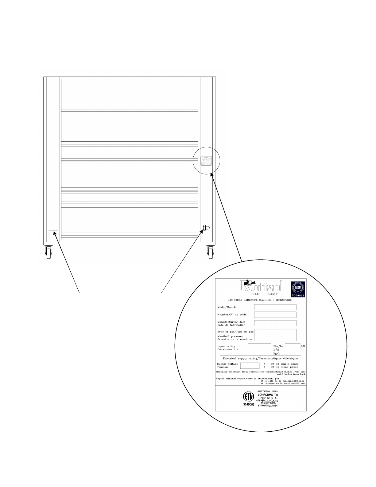
The plate is located on the back right in the middle of the amount.
1.2. TRADEMARK, MODEL, REFERENCE
Rôtissoires ROTISOL, model « GRANDES FLAMMES MILLENIUM », référence:
1675.8G, 1375.12G, 1375.8G, 1375.6G, 1375.5G, 1375.4G, 1375.2G, 975.8G, 975.6G, 975.5G,
975.4G et 975.2G.
All this information are the property of Rotisol.
Reproduction partial or in totality are prohibited without authority prior written of company Rotisol.
0,322014011606251025975.4G
0,43019516457001025975.6G
0,5530190116062514251375.5G
0,6445300164562514251375.8G
0,630320161070014451375.12G
0,645300164570014251375.6G
0,2910708006251025975.2G
0,352014011606251025975.5G
0,443019516456251025975.8G
0,491510080062514251375.2G
0,5230190116062514251375.4G
0,6451350164562517251675.8G
Electrical power
(kw)
Gas
power (kw)
weight
(kg)
Height
(mm)
depth
(mm)
Lenght
(mm)
Référence

1.3. SITE OF MANUFACTURERS PLATE
It is situated on the rear, right hand side of the unit.
GAS INLET
ELECTRICAL
CONNECTION
Rear of the rotisserie
All this information are the property of Rotisol.
Reproduction partial or in totality are prohibited without authority prior written of company Rotisol.

1.4. COMPULSORY MARKINGS
1.4.1. ON THE ROTISSERIE AND ON THE PACKING
All this information are the property of Rotisol.
Reproduction partial or in totality are prohibited without authority prior written of company Rotisol.

2. SETTING UP UNIT AND STARTING UP
•Before connecting and starting up the rotisserie. Ensure that the gas and electrical connections are
present.
This work are at the client cost, that he needs to have done by are a agreed company, near the
position that the rotisserie is to be les faire exécuter, par des sociétés.
The new air flow require for the combustion is : 2 m3/h par kW of the calorifique flow.
2.1. SETTING UP
2.1.1. UNPACKING
Unpack the rotisserie that is circled, filmed and fixed on palette
.
2.1.2. INSTALLING THE UNIT NEXT TO WALLS
AND APPLIANCES
The unit with glace door open should be placed at a distance
minimum of 20mm to adjacent walls.
2.1.3. APPLIANCE EQUIPPED WITH WHEELS
The device must be placed on a perfectly level ground and
locked in a stationary position for use and et le stockage
.
2.1.4. ENVIRONNEMENT
The device should not be installed near the steam,grease
(frying,…), projections of water, high températures or other
adverse condition.
2.2. GAS CONNECTION
The gas supply pipe will be sized to minimize losses power. It’s diameter will be determined
in function to it’s route (length, number of bends etc...) and the total power rating of the unit.
« Check that the settings of the unit corespond to the nature and preassure of the gas at the
premises.
In order to check the pressure of the unit, you just need to attached a manometer to the water gage at the
gas inlet on the rear of the unit, with all the burners on full.
The pressure measured should be the same as that indicated on the gas label, stuck to the unit.
The gas supply valves require no rotisserie set-up during their lifetime.
2.2.1. GAS CIRCUIT DIAGRAM
All this information are the property of Rotisol.
Reproduction partial or in totality are prohibited without authority prior written of company Rotisol.
Gas stopcock
Maxitrol regulator
Pilot
Thermocouple
Injector / Injector Support
Adjusting ring of the primary air
Gas cock
Knob ring
Gas knob
Gas line
Burner
Gas connection Ø 20/27

2.2.2. POSITION OF THE THERMOCOUPLE & PILOT LIGHT
2.2.3. POSITION OF THE INJECTOR AND THE SLEEVE FOR THE AJUSTMENT OF
THE PRIMARY AIR.
All this information are the property of Rotisol.
Reproduction partial or in totality are prohibited without authority prior written of company Rotisol.

FIXED
2.2.4. FIXED INSTALATION –MOBILE INSTALATION
All this information are the property of Rotisol.
Reproduction partial or in totality are prohibited without authority prior written of company Rotisol.
Connection type union 1 or 2
The use of TURBOGAS or similar in professional fixed instalations,willpermit a total liberty in the
conception of the kitchen.
MOBILE
The conception of a kitchen with mobile gas appliance is possible thanks to a tamdem of
TURBOGAZ-TUSHGASorSIMILAR.
FLEXIBLE PIPPING IN THE SHAPE OF UU
Measure of the gas flow under 20 mbar in kW/h PCI(natural gaz)

2.3. ELECTRICAL CONNECTION
Check that there is no errors with CONNECTION.
•Electrical rating : 230V~50Hz.
•Check that the installed power corresponds with the characteristics on the signal plate
at the rear of the unit.
IN ALL CASES , CONNECT THE EARTH WIRE
THE UNIT IS DELIVERED IN MONOPHASE + EARTH
2.4. EVACUATION - SMOKE TYPE : A
•The unit is destined to be installed under an extraction system with ventilation
•A heat delector with holes is placed above the rotisserie
VIEW FROM ABOVE
All this information are the property of Rotisol.
Reproduction partial or in totality are prohibited without authority prior written of company Rotisol.
108513751375-12G
685975975-8G
685975975-6G
108513751375-6G
108513751375-8G
108513751375-5G
108513751375-4G
138516751675-8G
685975975-2G
685975975-4G
685975975-5G
108513751375-2G
Measurement
B (mm)
Measurement
A (mm)
Reference

3. ADAPTING THE UNIT IN THE CASE OF CHANGING FROM ONE GASTO ANOTHER
3.1. CHANGING THE INJECTOR
3.3. ADJUSTMENT OF THE PRIMARY AIR
You need to adjust the opening of the air sleeve to dim. D coresponding to the type of gas used ( see
position of the air sleeve, chapter 2.2.3 and the table of adjustment of the burner, chapter 3.7).
3.3.
TABLE FOR ADJUSTMENT OF ONE BURNER
TIGHTENING
RINGS
GAS SUPPLY PIPE
ELBOW OF 90°
ELBOW NUT OF 90°
INJECTOR HOLDER
INJECTOR
AIR INLET
SLEEVE
BURNER
SLEEVE FOR THE
ADJUSTMENT OF
PRIMARY AIR
ELBOW NUT OF 90°
All this information are the property of Rotisol.
Reproduction partial or in totality are prohibited without authority prior written of company Rotisol.
12,59,56,55Presure at the tap for the reduced flow in mbar
7,57,57,57,5Reduced heat flow in KW
1,161,16--Mass flow kg/h
--1,851,59Flow volumein m3/h
452,52,5
Opening of the primary air
« D » in mm (chapitre 2.2.3)
1,822,92,9Diamete rof injector in mm
180200290290injector making
15151515Heat flow in kW
GF 1375
12,59,555Presure at the tap for the reduced flow in mbar
8,58,58,58,5Reduced heat flow in KW
1,321,32--Mass flow kg/h
--2,091,8Flow volumein m3/h
4513,513,5
Opening of the primary air
« D » in mm (chapitre 2.2.3)
1,92,153,13,1Diamete rof injector in mm
190215310310injector making
17171717Heat flow in kW
GF 1675
12,59,56,55Presure at the tap for the reduced flow in mbar
5555Reduced heat flow in KW
0,7760,776--Mass flow kg/h
--1,231,06Flow volumein m3/h
452,52,5
Opening of the primary air
« D » in mm (chapitre 2.2.3)
1,51,652,42,4Diamete rof injector in mm
150165240240injector making
10101010Heat flow in kW
GF 975
G31 under 50 mbarG31 under 37 mbarG25 under 25 mbarG20 under 20 mbarCARACTERISTICSMODEL


3.5. ADJUSTEMENT OF THE REDUCE FLOW
3.5.1. ADJUSTMENT OF REDUCED FLOW
Connect a manometeron the pressure plug and adjust to the pressure required ( see table of :
categuories of gas, chapter 3.1.1) with the aide of the reduced flow screw:
SEAL THE ADJUSTMENT.
3.5.2. ADJUSTMENT OF LOW SETTING
Put the tap to the « minimum » setting.
Connect a manometer on the preassure plug and adjust the pressure to that require ( see table
for adjustment of burner, chapter 3.7) with the aide of the low setting screw.
SEAL THE ADJUSTMENT
All this information are the property of Rotisol.
Reproduction partial or in totality are prohibited without authority prior written of company Rotisol.
3.4. LABEL SET
The label specifying the setting of gas to the appliance must be attached to it (see mandatory, chapter
1.4.1.). In case of change of gas, the new label comes with the new injectors.

All this information are the property of Rotisol.
Reproduction partial or in totality are prohibited without authority prior written of company Rotisol.
3.6. TABLE FOR THE ADJUSTMENT OF THE SECONDARY AIR
5555
UPPER
GF 975-4 5555
MIDDLE
5555
UPPER
GF 975-6 5555
MIDDLE
closedclosedclosedclosedLOWER
5555
UPPER
GF 1375-4
5555
MIDDLE
5555
UPPER
GF 1375-6 5555
MIDDLE
closedclosedclosedclosedLOWER
5555
MIDDLE
5555
UPPER
GF 1375-8
5555
UPPER
GF 1375-2
5555
MIDDLE
5555
UPPER
GF 1375-5
5555
UPPER
GF 975-2
5555
MIDDLE
5555
UPPER
GF 975-5
closedclosedclosedclosedLOWER
5555
MIDDLE
5555
UPPER
GF 1375-12
closedclosedclosedclosedLOWER
5555
MIDDLE
5555
UPPER
GF 1675-8
closedclosedclosedclosedLOWER
5555
MIDDLE
5555
UPPER
GF 975-8
Dim « S » in
G31 under 50
mbar
Dim« S » in
G31 under 37
mbar
Dim « S » in
G25 under 25
mbar
Dim « S » in
G20 under 20
mbar
SHUTERMODEL

4. ELECTRICAL DRAWING
For the rotisserie 1675.8, there are 8 motors and 2 halogen lamps.
For the rotisserie 1375.12, there are 6 motors and 1 halogen lamp .
For the rotisserie 1375.8, there are 8 motors and 1 halogen lamp.
For the rotisserie 1375.6, there are 6 motors and 1 halogen lamp.
For the rotisserie 1375.5, there are 5 motors and 1 halogen lamp.
For the rotisserie 1375.4, there are 4 motors and 1 halogen lamp.
For the rotisserie 1375.2, there are 3 motors and 1 halogen lamp.
For the rotisserie 975.8, there are 8 motors and 1 halogen lamp.
For the rotisserie 975.6, there are 6 motors and 1 halogen lamp.
For the rotisserie 975.5, there are 5 motors and 1 halogen lamp.
For the rotisserie 975.4, there are 4 motors and 1 halogen lamp.
For the rotisserie 975.2, there are 3 motors and 1 halogen lamp.
All this information are the property of Rotisol.
Reproduction partial or in totality are prohibited without authority prior written of company Rotisol.

5. SPARE PARTS
5.1 CENTRE PART
5.1.1 NOMENCLATURE
1BASE 116758G0101 1675
13758G01 1375
9758GF01 975
2FRAME 1 5484 1675-8
5501 1375-8
5502 1375-5
1375-4
5503 1375-2
5504 975-8
5500 975-5
975-4
5505 975-2
3DEFLECTEUR WITH HOLES 1DES105 1675
DES104 1375
DES103 975
4BANNER 1GFG81601 1675
GFG13804 1375
GFG59501 975
5PARABOLE TYPE 2 116758G09 1675
13758G09 1375
9758GF09 975
6GLASS HOLD 213758G11 1675
21375
1975
7SUPPORT HALOGENE 213758G10 1675
21375
1975
8SUPPORT HALOGENE LAMP 2 SUPR7S78 1675
21375
1975
9HALOGENE LAMP 2 LA78NM 1675
21375
1975
10 GLASS 2 PLAVERRE 1675
21375
1975
11 GLASS BLOCKING AT HALOGENE 213758G11 1675-8
1375-8
1375-5
1375-4
975-8
975-5
975-4
113758G11 1375-2
975-2
12 SUPPORT LEFT OF TRAY 1 13758G43 1675-8
1375-8
1375-5
1375-4
975-8
975-5
975-4
13 SUPPORT RIGHT OF TRAY 1 13758G44 1675-8
REFERENCE
DESIGNATION
GRANDES FLAMMES MODEL
REP
QTE
AllthisinformationarethepropertyofRotisol.
ReproductionpartialorintotalityareprohibitedwithoutauthoritypriorwrittenofcompanyRotisol.

(follow) 1375-8
1375-5
1375-4
975-8
975-5
975-4
14 MIDLE DRIP TRAY 1 PLAT165H 1675
PLAT1375H 1375
PLAT950H 975
15 DRAIN PLUG 1BV284 1675-8
1375-8
1375-5
1375-4
975-8
975-5
975-4
16 DRAIN PLUG 1 BV5000 TOUT LES MODELES
17 DRIP TRAY 1 PLAT16GT 1675-8
PLAT13GT 1375-8
1375-5
1375-4
PLAT96GT 975-8
975-5
975-4
18 SUPPORT BURNER 3 SUPPORT BRULEUR (1675) 1675-8
3 SUPPORT BRULEUR (1375) 1375-8
2 1375-5
2 1375-4
1 1375-2
3 SUPPORT BRULEUR (975) 975-8
2 975-5
2 975-4
1 975-2
19 BURNER 3 BRU1650NM 1675-8
3 BRU1350NM 1375-8
2 1375-5
2 1375-4
1 1375-2
3BRU975NM 975-8
2 975-5
2 975-4
1 975-2
20 BURNER COVER 3 GFC1650 + GFCA950 1675-8
3GFG13809 1375-8
2 1375-5
2 1375-4
1 1375-2
3GFCA950 975-8
2 975-5
2 975-4
1 975-2
21 SUPPORT OF CAST IRON PLATE 3 SPP 1675 1675-8
(see next page) 3 SPP 1375 1375-8
MODELE GRANDES FLAMMES MODEL
REP
DESIGNATION
QTE
REFERENCE
AllthisinformationarethepropertyofRotisol.
ReproductionpartialorintotalityareprohibitedwithoutauthoritypriorwrittenofcompanyRotisol.

(suite) 2 1375-5
1375-4
11375-2
3 SPP 975 975-8
2975-5
975-4
1975-2
22 CAST IRON PLATE 27 PLPICOT5166 1675-8
21 1375-8
14 1375-5
1375-4
7 1375-2
12 PLPICOT5166 (1) 975-8
8 975-5
975-4
4 975-2
22B SAMLL CAST IRON PLATE 3 PLPICOT5419 975-8
2 975-5
975-4
1 975-2
23 SPACER CAST IRON PLATE 6GFG13815 1675-8
1375-8
975-8
4 1375-5
1375-4
975-5
975-4
2 1375-2
975-2
24 AXE CAST IRON PLATE 3 ROND12/137 1675-8
3ROND12/108 1375-8
2 1375-5
2 1375-4
1 1375-2
3ROND12/68 975-8
2 975-5
2 975-4
1 975-2
25 BLOCKING ROD CAST IRON PLATE 6 TIGE123 1675-8
1375-8
975-8
4 1375-5
1375-4
975-5
975-4
2 1375-2
975-2
26 ISULATION 3 NEFALIT71650 1675-8
3NEFALIT71350 1375-8
2 1375-5
1375-4
11375-2
3 NEFALIT7 975-8
MODELE GRANDES FLAMMES
REP
DESIGNATION
QTE
REFERENCE
AllthisinformationarethepropertyofRotisol.
ReproductionpartialorintotalityareprohibitedwithoutauthoritypriorwrittenofcompanyRotisol.

(follow) 2 975-5
975-4
1 975-2
27 VAUGIRARD PLATE MIDDLE / LOWER 48 BRI2205415 (1) 1675-8
19 1375-5
1375-4
1375-2
24 975-8
12 975-5
975-4
975-2
28 SUPPLEMENT BRICK MIDDLE / LOWER 413758G47 1675-8
4 1375-8
2 1375-5
1375-4
1 1375-2
2GFG51327 975-8
1 975-5
975-4
975-2
29 BRICK HOLDER MIDDLE / LOWER 2GFMAIN16 1675-8
2GFG13821 1375-8
1 1375-5
1375-4
1375-2
2GFMAIM84 975-8
1 975-5
975-4
975-2
30 SUPPORT BRICK MIDDLE / LOWER 2GFAR581 1675-8
2GFG13819 1375-8
1 1375-5
1375-4
1375-2
2GFAR950 975-8
1 975-5
975-4
975-2
31 VAUGIRARD PLATE UPPER 24 BRI2205415 1675-8
19 1375-8
1375-5
1375-4
12 975-8
975-5
975-4
32 SUPPLEMENT BRICK UPPER 213758G46 1675-8
1375-8
1375-5
1375-4
2GFG51326 975-8
1 975-5
975-4
33 BRICK HOLDER UPPER 1GGFMI8165 1675-8
GRANDES FLAMMES MODEL
REP
DESIGNATION
QTE
REFERENCE
AllthisinformationarethepropertyofRotisol.
ReproductionpartialorintotalityareprohibitedwithoutauthoritypriorwrittenofcompanyRotisol.

(follow) 1GFG13824 1375-8
1375-5
1375-4
1GFMI595 975-8
975-5
975-4
34 TIGHTNER FOR REAR FRAME 3 RA8B16 1675-8
3GFG13814 1375-8
2 1375-5
1375-4
1 1375-2
35 SUPPORT FOR UPPER BRICKS 3 GFAR9BNM 1675-8
3GFG13822 1375-8
2 GFAR5BRH 1375-5
1375-4
3GFA958NM 975-8
2 GFAR5BET 975-5
975-4
36 AJUSTER OF AIR INTAKE 3GFREG165 1675-8
3GFG13818 1375-8
2 1375-5
1375-4
1 1375-2
3 GFREG950 975-8
2 975-5
975-4
1 975-2
37 REAR 3 GFAR1651 1675-8
3GFG13817 1375-8
2 1375-5
1375-4
1 1375-2
3 GFAR0951 975-8
2 975-5
975-4
1 975-2
38 REAR LOWER PLATE 1 GF16CU10 1675
GFG13813 1375
GF953CU10 975
GRANDES FLAMMES MODEL
REP
DESIGNATION
QTE
REFERENCE
AllthisinformationarethepropertyofRotisol.
ReproductionpartialorintotalityareprohibitedwithoutauthoritypriorwrittenofcompanyRotisol.
This manual suits for next models
11
Table of contents