roundhouse LOCOGLYDE User manual
Electronic Speed Controller
ROUNDHOUSE ENGINEERING CO. LTD.
Units 6-10 Churchill Business Park. Churchill Road.
Wheatley. Doncaster. DN1 2TF. England
Telephone 01302 328035 Fax 01302 761312
Email mail@roundhouse-eng.com
www.roundhouse-eng.com
ONLINE
Please read the instructions carefully before use. If there is anything that you do not understand
or are unsure of, check with Roundhouse before fitting.
Installing the Roundhouse LocoGlyde Electronic Speed Controller.
Mount the LocoGlyde Electronic Speed Controller (LESC) as far as possible away from the receiver
to avoid any interference. Care should be taken to position the LESC so that it is kept as cool as
possible. Ensure that the motor being used is fitted with 2 motor capacitors (0.1uF) - one from
the negative terminal to the can and one from the positive terminal to the can.
Receiver Connections
The servo load on the LESC is
wired for all current R/C
manufacturers apart from
Airtronics - for these receivers
the black and red wires require
swapping in the plug.
Receiver Type Position 1 Position 2 Position 3
Futaba, Sanwa, KQ White / Blue Red Black
Hi-Tec Yellow Red Black
Graupner, JR, Kyosho White / Orange Red Brown
Acoms Yellow Red Black
Airtronics White / Orange Black Red
N.B. The LESC requires a battery pack to be connected to the Tamiya connector to power it.
It is essential that the correct polarity is observed. If the battery pack is connected wrongly it
will immediately destroy the electronics in the speed controller which cannot then be repaired.
Connecting the battery pack incorrectly is not covered by the warranty.
LESC’s are fitted with a 1.2A BEC plug (Battery Eliminator Circuit). This means that the battery pack
powers the Speed Controller, and this in turn supplies power to the receiver - Do Not connect a
separate battery pack to the receiver.
Features of this Unit:-
100% Waterproof
10A motor limit
6.0V to 14.4V Operating voltage
0.025V drop at 10A
Maximum current rating, 10A
1.2A BEC
In built Directional Lighting
circuit
Optional directional lighting
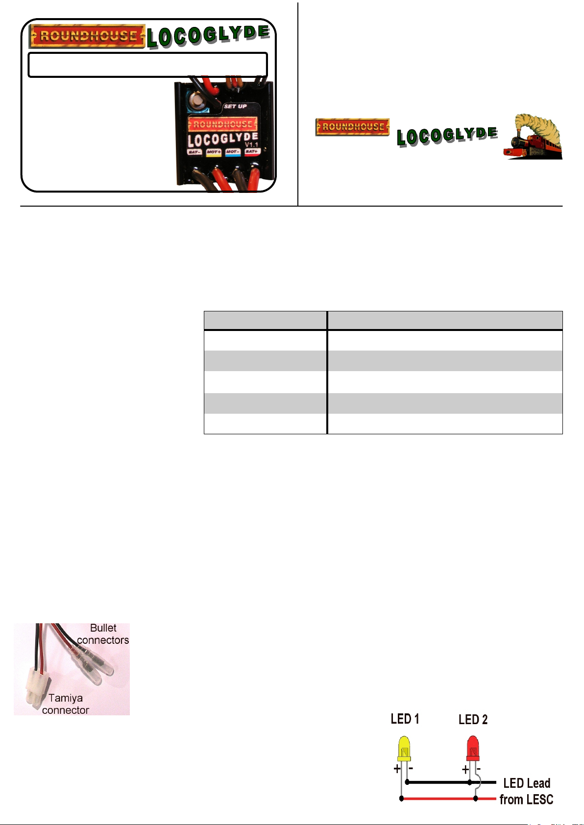
Incorporated in the LESC is a directional lighting circuit, which
allows up to 4 LED’s to be powered (max two in forward and two in
reverse). Connecting a couple of suitable LED’s (as shown in the
diagram opposite), to the thin black and red lead coming out of the
LESC, will result in one LED lighting up when running in either
direction. N.B. Do not use high-powered White or Blue LED’s.
Battery Connections
The LESC is fitted with a Tamiya style plug and bullet connectors.
Tamiya connector: Black = Battery –ve Red = Battery +ve
Bullet connectors: Red = Motor +ve Black = Motor –ve
N.B. Always disconnect LESC from battery cells when not in use.
N.B. - Be aware that this speed controller should only be used on a channel
which has a sprung neutral. If you intend using an Aircraft/Helicopter
Transmitter, Do Not plug the LESC into the Throttle side of the receiver. Doing
so will cause permanent damage to the LESC.

Trouble Shooting
When the LESC is turned on , the motor immediately starts to turn.
1. Check to see if the LESC is connected to the receiver properly. Check your transmitter is
turned on.
2. Try reprogramming the LESC.
3. If the motor is still turning after checking the above the unit may be damaged - Please contact
Roundhouse Engineering Co. Ltd.
Throttle stutters under acceleration.
1. The receiver or aerial may be too close to the main power wires (see installation section).
2. Poor connection to the battery or motor. Check all connections are making good contact.
3. Motor brushes may be worn - replace the motor or brushes if possible.
4. Excessive current is being drawn by the motor - use a less powerful motor.
The speed controller keeps cutting out.
1. The motor is too powerful for this controller - use a milder motor (observe the stated motor
limit).
2. The LESC is getting too hot - try to position the LESC so as to get more airflow across it.
3. Possible internal damage to the LESC - contact Roundhouse Engineering Co. Ltd.
Motor runs backwards.
1. The motor is wired backwards - check your wiring.
ROUNDHOUSE ENGINEERING CO. LTD.
Initial Set-Up Procedure
The unit has been pre-set at the Roundhouse Factory and should work with most configurations.
To use the pre-set configuration, follow steps 1 to 6 then stop. If you require different settings,
follow all the steps below, 1 to 12.
1. Plug the LESC into the receiver. Ensure plug is fitted with the signal wire facing inward toward the
receiver label.
2. Connect the Red wire bullet connector to the positive on the motor.
3. Connect the Black wire bullet connector to the negative on the motor.
4. Switch on the transmitter ensuring all control positions and trims are central.
5. Plug the Speed Controller into the power source (battery), ensuing polarity is correct (Tamiya
connector).
6. Switch on the LESC. If the factory settings are suitable, there is no need to complete the steps 7 - 12.
7. Disengage motor to prevent the movement during LESC set-up.
8. Switch on the LESC and wait two seconds then press the set up button - the neutral setting will be
now stored.
9. Move the throttle control forward to position where you want full forward speed to be.
10. Move the throttle control back to the neutral position. The LESC will now store the full forward speed
setting.
11. Move the throttle control backward to position where you want full reverse speed to be.
12. Move the throttle control back to the neutral position. The LESC will now store the full reverse speed
setting. The motor can now be reconnected.
The LESC should now be programmed correctly. If you need to reprogram the LESC at anytime then just
follow the above instruction from step 7 through to 12.
The diagram gives an example of how the LESC may be connected to operate a motor. Please
note that the Receiver, Motor, LED and Battery Pack are not part of, or supplied with, this unit.
Table of contents
Popular Controllers manuals by other brands

Digiplex
Digiplex DGP-848 Programming guide

YASKAWA
YASKAWA SGM series user manual

Sinope
Sinope Calypso RM3500ZB installation guide

Isimet
Isimet DLA Series Style 2 Installation, Operations, Start-up and Maintenance Instructions

LSIS
LSIS sv-ip5a user manual

Rockwell Automation
Rockwell Automation 1769-L31 installation instructions


