Rousseau Router Lift LS User manual

1718 13th Street Clarkston, WA 99403
800-635-3416 • 509-758-3954 • Fax 509-758-4991
OWNER’S MANUAL
IMPORTANT
Read and understand all safety guidelines and
instructions carefully before operating.
Quality Router Accessories
Router Lift LS
3000REV.10-04
SETUP
CORNER SNUGGERS: The corner snuggers are designed to tighten plate position by pressing outward in all
four corners. They are not designed to clamp the plate down to the table.
1. Once router is mounted, place plate in top opening with starting pin holes to
the right side. Assemble Corner Snuggers™ through plate using hardware pro-
vided (Fig. 1).
2. To hold plate in position push Corner Snuggers™ into all four corners and
tighten.
INSERT RINGS: The insert rings are designed to snap together with a tight fit,
so that they will stay securely in place.
To remove and replace the rings you may need to apply considerable force. We
recommend tapping the rings gently but firmly using a soft mallet or piece of wood.
If you desire a looser fit, you may lightly sand the inside diameter of the plate and red ring.
When replacing red ring the tab on underside must line up with one of the two notches in plate.
OPERATING INSTRUCTIONS
To get the most versatility and safety from your router table we highly recommend our router fences (3301 Basic or
3301DL Deluxe).
FREEHAND OPERATION: The starter pin is included for freehand routing of curved pieces, using a pilot bearing
bit. Caution: Never rout freehand (w/out a fence) using a non-piloted bit. The starter pin may be used in one of the
two predrilled locations in the mounting plate or three locations in the red ring. To store the starter pin use the
predrilled hole in the back right of the mounting plate.
When using the starter pin, the feed direction of the workpiece is always right to left across the front of the bit.
Set the workpiece against the front of the starter pin and pivot it slowly into the bit.
Once the workpiece has contacted the bit’s pilot bearing move it away from starter pin.
While routing, make sure the workpiece is always in contact with the bearing.
Fig. 1
Models 3002, 3003 & 3004
™

GENERAL INFORMATION
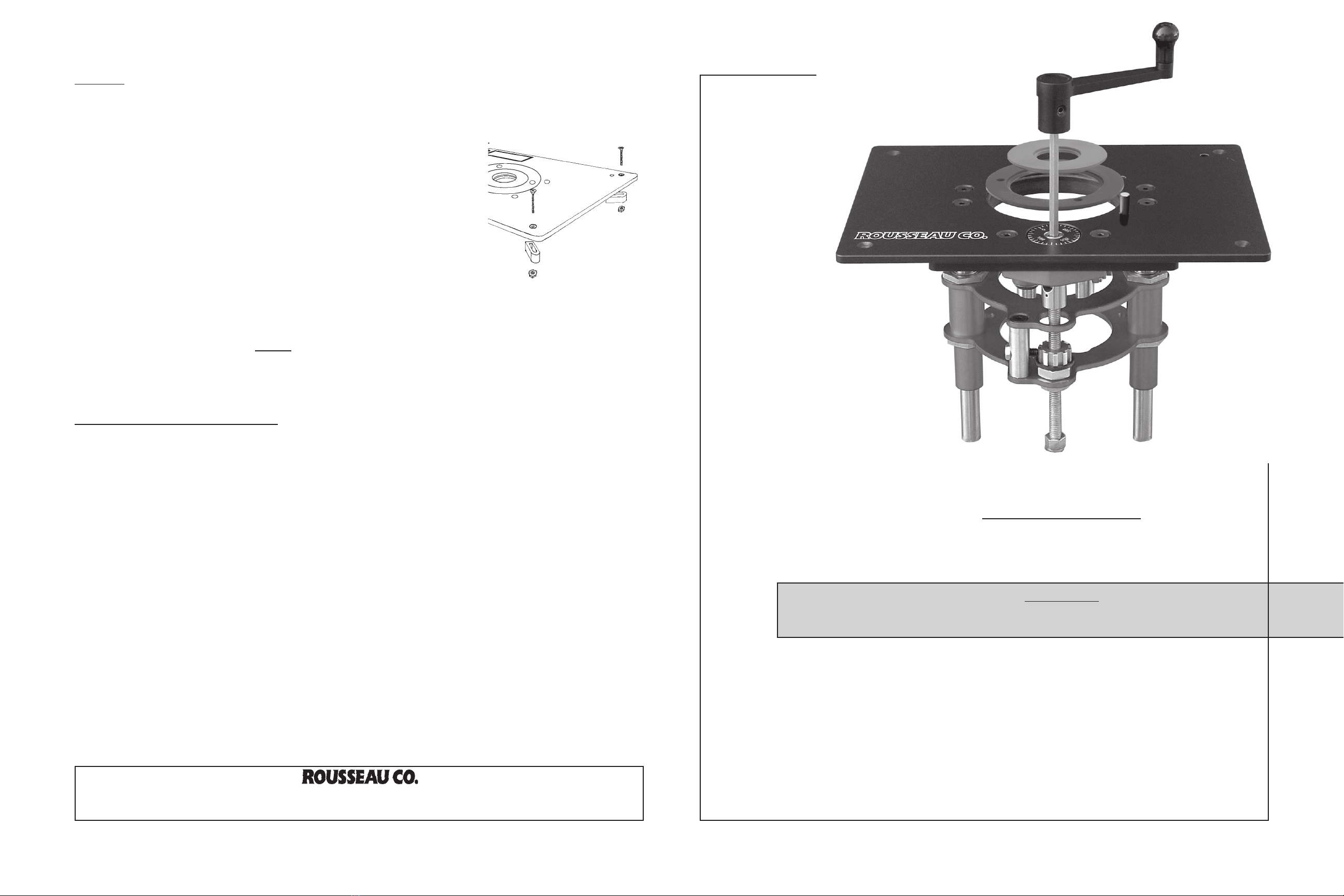
You have purchased a ROUSSEAU CO. 3000 SERIES ROUTER LIFT LS. This product is designed to allow quick
and easy bit height adjustment from the top of your table by fast and accurate raising and lowering of the router.
WARRANTY
This product has a lifetime warranty to the original purchaser that applies to defects in materials and workmanship
only. We will repair or replace the product or part(s) at our discretion. This warranty does not apply to product
failure or defects due to direct or indirect misuse, abuse, negligence, accidents, alterations, repairs or lack of
maintenance. The item must be shipped prepaid to our Clarkston, WA location. If items must be returned for
warranty service, call to receive a Return Goods Authorization (RGA) number and further instruction.
SAFETY GUIDELINES
THIS SECTION CONTAINS IMPORTANT SAFETY INFORMATION CONCERNING A HAZARD THAT MAY
CAUSE SERIOUS INJURY OR DEATH, and/or damage to stand or equipment if used improperly. Please read the
following instructions very carefully.
Always follow the safety recommendations and guidelines provided by the manufacturer of your
tools and supplies. When in doubt refer to your owner’s manual.
Always wear eye protection. Failure to do so may cause severe injury and/or loss of sight.
Always keep fingers clear of cutter. Failure to do so could result in serious injury or loss of fingers.
Never wear loose clothing while operating equipment. It may become entangled in router bit caus-
ing severe injury or death.
Always use guards and hold downs to protect you and your workpiece. Operation without guards
could result in loss of fingers, severe injury or death.
Carefully check router bits before each use. Do not use if damage or defect is suspected.
Unplug any tool or machine when changing bits or making mechanical adjustments.
OPERATION GUIDELINES
THIS SECTION CONTAINS IMPORTANT OPERATIONAL INFORMATION CONCERNING HAZARDS THAT
MAY CAUSE SERIOUS DAMAGE TO PRODUCTS OR TOOLS IF USED IMPROPERLY. Please read the
following instructions very carefully.
Never use a power drill to raise and lower the lift carriage. The amount of friction and heat will
cause premature wear of the threads
Never force the bit or overload the router.
Be sure at least ¾ of the shank on the bit is inserted securely in the router collet.
Never bottom the bit in the collet. Allow 1/8” clearance at bottom of bit.
Make sure router fence is locked into position before use.
Always rout in two or more passes when removing large amounts of material.
Reduce RPM speed for large diameter bits.
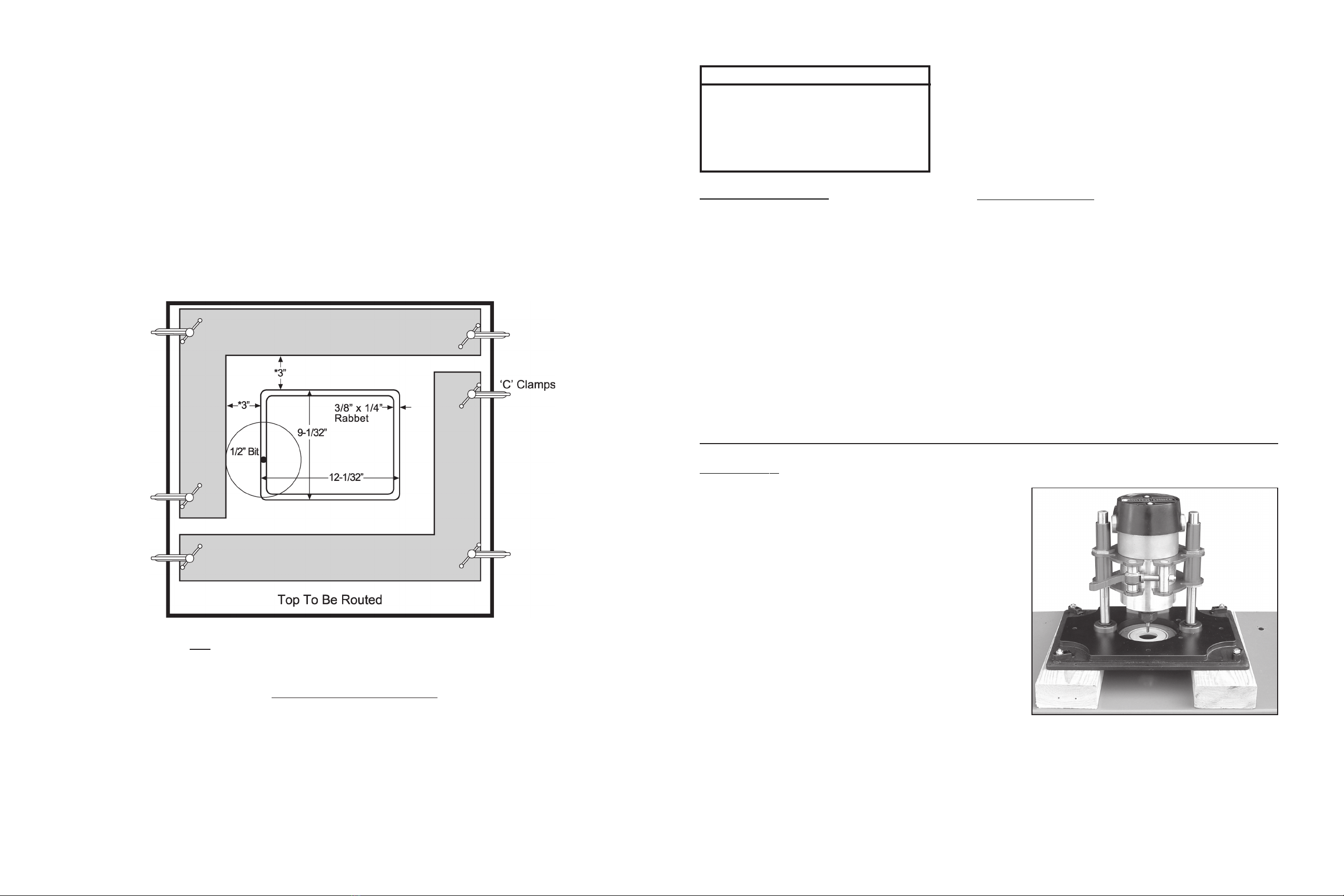
After routing the baseplate hole into your table by following the Baseplate
Installation Instructions or using the 3509-T Installation Template, proceed
through the following steps to install the leveling system.
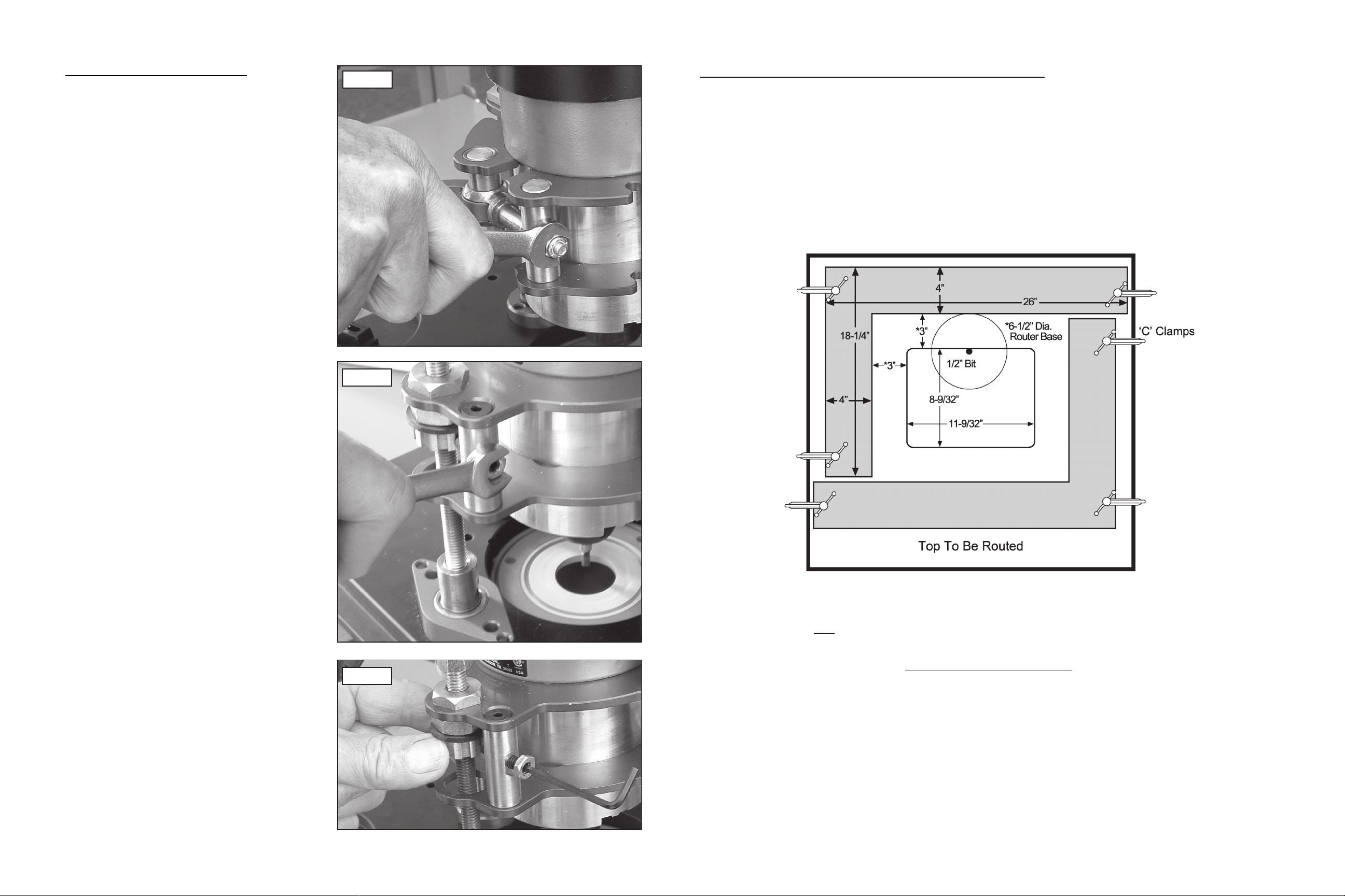
1. Mark the location for the six brass inserts. There will be one located in
each corner and one on each long side. Fig. A
2. Clamp a block of wood below the location of each hole to eliminate tear-
out. Drill each hole using a 7/32” drill bit. Take care to assure that the
holes are perpendicular to the tabletop. Fig. B
3. Press one insert into each hole from the top of the table until flush with the
surface. This can be done by threading the insert onto the end of a 10-24
screw (the corner snugger mounting screws will work) and driving it gently
with a hammer. Fig. C
4. Thread one nylon leveling screw into each insert from the bottom side of
table.
5. Place baseplate into the table and adjust each leveling screw to desired
height. Fig. D
NOTE: THE weight of the router should create sufficient resistance to
hold leveling screws in place. However, more resistance can be achieved
by distorting the leveling screw threads slightly using pliers. Fig. E
INSTALLATION OF BASEPLATE LEVELING SYSTEM
Fig. E
Fig. D
Fig. C
Fig. B
Drill 6-7/32 Holes
Centered In Routed Surface
Fig. A
Drill Into
Wood Block
To Prevent
Tear-Out
Drive Insert
Lightly With
10-24 Metal
Screw &
Hammer
Routed & Drilled
Table Top
Base Plate
Leveling
Screw
Table Top
Plier Jaws
Leveling Screw
Distort Thread with Plier to Tighten

ASSEMBLY
1. Using the crank handle, raise the lift carriage up until it just
contacts the O-rings at the top of the shafts.
2. With the router lift propped up on blocks (Fig 1) and the
cam lock open, slide the router all the way down through the
center of the router lift until it contacts the back plate. The
router’s collet can extend down through the center hole in
the base plate. Rotate the router until the switch controls on
the router are in a convenient position, back the router up
fromthebackplateabout1/16”andclosethecamlockclamp.
Ifthe clamp seemstoo loose orthe router moveswhile being
used or the clamp won’t close, go to step 3 to adjust the
cam lock clamp; otherwise, go to step 4.
3. To adjust the cam lock clamp, use a 7/16 wrench to loosen
or tighten the lock nut holding the cam lock clamp (Fig 2). A
small adjustment should be all that is needed. Test and
repeat in small increments until a correct fit is achieved.
Clamp router in place as described in step 2.
4. The lift is now ready for your router table. The Rousseau Router Lift is designed to fit Rousseau router tables,
Rousseau router table tops and is interchangeable with Rousseau Deluxe Base Plates. See “Installing Base
Plate into a Blank Table Top” on next page to make your own router table.
PARTS INCLUDED
ROUTER LIFT PLUS
Height Adjustment Wrench
9” x 12” Phenolic Resin Base Plate
4-1/16” Dia. Red Insert Ring Ring
2-7/8” Dia. Grey Insert Ring
Starter Pin
LEVELING SYSTEM
6 Brass Inserts
6 Nylon Thumb Screws
CORNER SNUGGERS
4 Corner Snuggers
4 screws
4 nuts
Note: Double stick tape may be substituted for clamps if necessary. Use 2” wide tape the full length of ‘L’ jigs.
4. Cut the thru hole following the jigs with 1/2” dia. straight flute bit.
Note: To minimize chip out use a up cut spiral bit.
5. Release clamps and move ‘L’ jigs out 3/8” all around (Fig. 2).
6. Re-clamp jigs and set router bit depth to 5/16”.
7. Rout out rabbet 3/8” W X 5/16” D following the jigs with 1/2” dia. straight flute bit..
Note: To minimize chip out, use a down cut spiral bit.
*The 3” figure relates only to a 6-1/2” diameter router base. If you have a router base of a different size your offset
will also be different. To figure out the distance needed between the ‘L’ jigs and the cut, use the following formula:
Cutting Rabbeted Edge
Fig. 2
SUGGESTED ROUTER BIT SPEEDS
BIT DIAMETER MAX. SPEED
1” (25mm) 24,000RPM
1-1/4” - 2” (30-50mm) 18,000RPM
2-1/4” - 2-1/2” (55-65mm) 16,000RPM
3” – 3-1/2” (75-90mm) 12,000RPM
( Diameter of Base - 1/2”)
2
TOOLS NEEDED
7/16 End Wrench
1/8 Hex Key Wrench
Phillips Screw Driver
Router
Router Bit
Hand Drill or Drill Press
Clamps
Router Bit
Mallet or Hammer
Fig. 1

INSTALLING BASE PLATE INTO ABLANK TABLE TOP
If you do not have our Base Plate Installation Kit (3509-T), follow the instructions below.
1. Make two hardboard ‘L’ jigs approximately 18-1/4” x 26” - outside dimensions (Fig. 1).
2. Decide where you want the base plate located in the table and mark its outer edges. Then measure in 3/8” in
on each edge for the location of the thru hole.
3. Lay the ‘L’ jigs on table and clamp them in place offset 3” *from the thru hole (Fig. 1).
Cutting Thru Hole
Fig. 1
INSTRUCTIONS FOR USE
1. With the adjustment handle in the hex socket
in the middle of the dial, turn the handle
clockwise to raise your router and counter-
clockwise to lower the router. One revolution
movestherouter 1/16”. Remove handlebefore
using router.
2. If bit height changes during use, check the
following:
a. Make sure collet is tight and router bit is not
slipping in collet.
b. Makesurecam lock clampistight and router
is not slipping in lift.
c. Depending on usage, thread tension needs
to be reset periodically.
Reset thread tension by first turning the lift
upsidedown ona tablewith theadjustment rod
facingyou. Usinga7/16wrench,(Fig.3)loosen
the1/4” hex nutlocated on theside of thebrass
post. Next, use a 1/8” hex key wrench to back
outthesetscrewinsidethenutuntilthevertically
grooved brass collar can be turned (Fig. 4).
Then, rotate this brass collar so it tightens
against the rubber washer. Note: a drop of oil
on the rubber washer eases rotation of the
brass collar. Finally, tighten the setscrew into
one of the vertical grooves on the brass collar
and tighten the nut.
*The 3” figure relates only to a 6-1/2” diameter router base. If you have a router base of a different size your offset
will also be different. To figure out the distance needed between the ‘L’ jigs and the cut, use the following formula:
( Diameter of Base - 1/2”)
2
Fig. 2
Fig. 3
Fig. 4
This manual suits for next models
3