Rover RLT-1550 D10 User manual

A STEP AHEAD IN DIGITAL TELEVISION
Product made in Italy by Rover Broadcast.com
• Theultrawideband,47-2.700MHz,optical,laser
transmitter,Rover“RLT”series,equipsahigh
performance,isolatedandthermally-stabilized,DFB
laserwithextremesuperiorlinearity,designedfor
highchannelloading,analog/digitalCATV
andSATsignals.
• The“RLT”seriesoperatesata1550nmwavelength,
accordingtoITU-GRID,theunitisdesignedfor
advanced,singlemode,optical,brenetworks,
withDWDMITU-grid(DenseWavelengthDivision
Multiplex),orCWDMgrid(CoarseWavelength
DivisionMultiplex).
• Finetuning(±100GHz)availableforDWDMversion,
toenableonechannelreconguration.
• TheunitemployssuperiorCSO&SBSpre-correction,
reducinglaserandberdispersioneects.
• RLTSeriesLaserTransmittersincorporatea
comprehensivealarmstatusmonitoringsystemof
alllaseroperatingparameterssuchas:Dclaserbias
current,laseroutputpower,OMI,AGCstatus,etc.
TheUSBandLANportsprovideaccesstothe
completeoperatingparametercongurationandto
thealarmmonitoring.
R LT–1550 d10
47-2.700 MHz OPTICAL DISTRIBUTION EXAMPLE
DWDMHighPower,UltraWideBandCATV&SAT47-2.700MHzLaserOpticalTransmitter,
withpre-correction,LANremotecontrolandalarms
ROVER LASER TX
mod. RLT-1550 D10
47-2.700 MHz
FIBER
NODE
OPTICAL
SPLITTER
EDFA
OPTICAL
AMPLIFIER
20 Km
Fiber
30 Km
Fiber
COAX COAX
COAX
H.E.

Product made in Italy by Rover Broadcast.com
BLOCK DIAGRAM
MAIN FEATURES
• LownoisehighlinearityDFBlaserforexcellentRIN
• Highstabilitythermoelectriclasercooler(DWDM
version)
• CATVinput47-870MHz(oropt.47-1.002)foranalog
TVanddigitalQAMsignals
• TwoseparateCATVinputs,forstandardleveland
highlevelsignals
• SATinput950-2.700MHzfordigitalSAT
transponders
• Inputlevelsignaltestpointonfrontpanel
• Laserdriverleveltestpoint(forOMImeasurement),
onfrontpanel
• ITU-Gridwavelengthnetuning+/-100GHz,
availableforDWDMversion,toenableoneoptical
channelreconguration
• Laseroutputpoweravailable,from+4to+10dBm
• AutomaticchannelsloadcontrolforstableOMI
• Allparametersandpre-corrections,adjustablevia
USB/LANport:outputlaserpower,wavelength
netuning,slope,gain(AGC),OMI,SBS,CSO
predistorsion,chirp.
• USBandLAN-portforlocal&remotecontrol
interface
• SC/APClaseroutputconnector
• Laseroutputconnectoravailableonfront,
orrearpanel
• Built-in2or4wayopticalsplitter,opt.
• RedundancyPSU:2x230Vacopt.
or1x230Vac+1x48Vdcopt.
• Slim,1Unit,19”Rack
2
SATinput
950-2.700MHz
CATVinput
47-870MHz
HILevelCATVinput
47-870MHz
1T.P.CATVinputlevel
-20dB
2T.P.CATV
laserdrivelevel
SMLaser
output

Product made in Italy by Rover Broadcast.com
TECHNICAL SPECIFICATIONS
CAT V & SAT
CATVfrequencyrange
47-870MHz(opt.30-1.000noSAT)or(opt.5-1.000MHzTVonlyforquantityorders,noSAT)
SATfrequencyrange 950-2.700MHz
RFconnectors 75ohmtype“F”
RFReturnLoss TV=>16dB
SAT=>12dB
TypicallevelforCATVmaininput 80dbuV/CHtyp.(72minimum)
TypicallevelforhighlevelCATVinput 100dbuV/CHtyp.(terminatewith75Ωloadifnotused)
NominallevelforSATinput 92dbuV/Trasp.(90minimum),(terminatewith75Ωloadifnotused)
Testpoint1mainCATVinput inputlevel-20dB
Testpoint2laserdrivelevel 80dbuV/5%OMI(relatedtoch.load)
Gainmode CATV:AGC(orManual,notrecommended)
SAT:Manual
GainadjustmentrangeCATV manual+11/-11dB,AGC30dBMax
SlopeadjustmentrangeCATV -3/+15dB
LASER
DWDM version CWDM version
Lasertype DFBCooledbuttery DFBuncooledcoaxial
Opticalwavelength ITUgrid100GHz,channels20to60
available(1.530to1.560nmapprox) 1.550+/-4nm
Powerstability +/-0.5dB +/-1dB
Opticalpoweradjustment 0to-3dB
Wavelengthnetuning -100to+100GHz,50GHzsteps
RIN -155dB/Hzworstcase -150dB/Hzworstcase
Opticalinsulation 30dBmin 30dBmin
Opticalreturnloss >45dB >40dB
PERIFERALS
LAN/ETHERNET10/100port HTMLbrowserforremotesettingsandmonitoring
USBport Forlocalsettings,monitoringandSWup-grades
POWER SUPPLIES
Mainpowersupply 230Vac50Hz
Redundancypowersupplyoptional 48Vdcor2nd230Vac
Powerconsumption <20W
MECHANICAL
Case Slim,19”rack,oneunit,
Weight 5kg
SAFETy, EMC, INSTALLATION ENVIRONMENT
Safety EN50083-1andEN60950
Seeyellowlabelontheequipment.
LaserSafety
Class1Macc.IEC60825-1(eyesafefornormalviewing).
Duringnormaloperationsthelaserbeamisconnedwithinopticalber.Optical
transmitterisintendedtoworkONLYconnectedtotheproperopticalnetwork
Installationenvironment Temperaturerange:–5°/+45°
AccordingtoETS300019-1-3Class3,1ControlledTemp.Loc.
Relativehumidity 90%(95max)
EMC EN50083-2
3

Product made in Italy by Rover Broadcast.com
Channelallocationplan,numberof
channels:Cenelec42,allch.FLAT
*Channelallocationplan,numberofchannels:
77AnalogNTSC+75DigitalQAMat–6dB
level,allch.FLAT
OMI(1.550nm)(DWDMVersion) 4,1%(1)
---%(2)
3,3%(1)
---%(2)
(CWDMVersion) ---%(1) ---%(1)
CNR(1550nm)(DWDMVersion) 53dB(1)
51,5dB(2)
52dB(1)
51dB(2)
(CWDMVersion) 51(1) 50,5(1)
CSO(1550nm)(DWDMVersion) >60dB(2) >60dB(2)
(CWDMVersion) >58dB(2) >58dB(2)
CTB(1550nm)(DWDMVersion) >62dB(2) >62,5dB(2)
(CWDMVersion) >64dB(2) >64dB(2)
CXM(1550nm)(DWDMVersion) >58dB(2) >57dB(2)
(CWDMVersion) >55dB(2) >55dB(2)
*Allch.FLAT,(analogchannelsbelow550MHz),(digitalchannelsabove550MHz)digitalQAMchannels–6dBlevel
LINKTYPE:
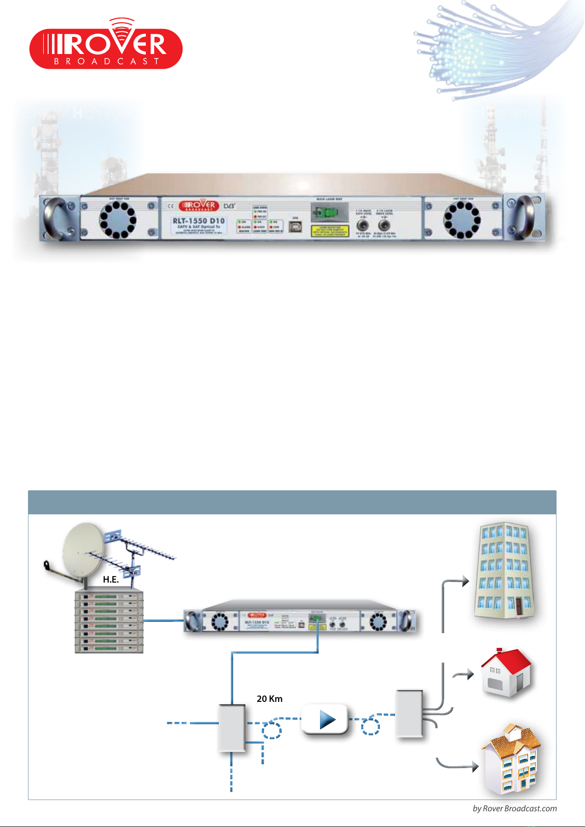
1)Linktype1=tx+0kmber+opticalattenuator+RX
2)Linktype2=tx+20kmberG652+opticalattenuator+RX
RX:receivedpower=0dBm,noisecurrent=7pA/√Hz
SAFETy
FULL LOAD CATV NETWORK PERFORMANCE
4
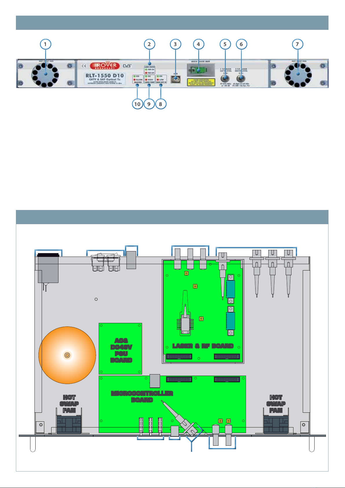
INVISIBLE LASER RADIATION, DO NOT STARE
INTO BEAM OR VIEW DIRECTLY WITH OPTICAL
INSTRUMENTS CLASS 1M LASER PRODUCT.
MAXIMUM OUTPUT POWER: 145.0 mW,
WAVELENGTH: 1550 nm IEC 60825-1:2007
(EN 60825-1:2007, DIN EN 60825:2008-05).
THE EqUIPMENT MAY ONLY BE INSTALLED BY
qUALIFIED PERSONNEL, WHO HAVE RECEIVED
THE NECESSARY TRAINING IN HANDLING OPTICAL
AND ELECTRICAL EqUIPMENT AND HAVE BEEN
INSTRUCTED IN LASER SAFETY.
Laserequipmentinstallation,operationandmaintenancemustonly
becarriedoutbypeoplewhohavereceivedadequatetraininginlaser
safety.
Opticaltransmittersandampliersemitopticalpowerintheinvisible
infra–redspectrumrange.Undernormaloperatingconditions,the
opticalpoweristransferredinthebersandisnotaccessible.
Eachopticaltransmitterandeachopticalamplierisassignedtoa
laserclassaccordingtoIEC60825–2andahazardlevelaccordingtoIEC
60825–2.
Thehazardlevelisbasedonradiationthatcouldbecomeaccessible
underreasonableforeseeablecircumstances,e.g.disconnectedber
connector,bercablebreak.
Bothlevelsaredocumentedintheaccordingoperatingmanualofthe
deviceandwithalasersafetylabelonthedevice.
Thedevicemaybeintegratedinanopticalbercommunicationsystem
(OFCS)complyingwithIEC60825-2.
ForsubsequentaccessiblelocationswithintheOFCS,themanufacturer
oftheOFCSisobligedtoassignappropriatehazardlevelsandtoinstall
applicablelasersafetymeasuresaccordingtoIEC60825-2.
NOTICE
WARNING
!

Product made in Italy by Rover Broadcast.com
FRONT VIEW
INTERNAL VIEW
11
22
1010
33
99
44
88
55
66
77
1. Hotswapfan
2. LEDLaserPWRstatusandalarm
3. USBport
4. MainLASEROUT.
ATTENTION:Laserradiation,donotviewdirectlywith
opticalintruments,class1Mlaserproduct
5. 1stTestPointmainCATVlevel:
47-870MHzat-20dB
6. 2ndTestPointlaserdrivelevel:
80dBµV,47-870MHz5%OMI+2∆Opt.Pwr
7. Hotswapfan
8. LEDmainCATVINstatusandalarm
9. LEDlasertempstatusandalarm
10.LEDAC/DCmainsstatusandalarm
5
HOT
SWAP
FAN
HOT
SWAP
FAN
AC&
DC48V
PSU
BOARD
MICROCONTROLLER
BOARD
LASER & RF BOARD
STATUS LED
USB
TEST
POINT
LASER
OUT
MAINS PSU SWITCH
LAN
CATV & SAT
INPUT
OPTIONAL REAR
LASER OUTPUT
N
X
P
N
X
P

Product made in Italy by Rover Broadcast.com
REAR VIEW WITH 2 x 230 Vac P.S.U.
REAR VIEW WITH 1 - 230 Vac and 1 - 48 Vdc P.S.U.
11
22
33
44
99
55
1111
66
1212
77
1010
88
1313
11
22
33
44
99
55
1111
66
1212
77
1010
88
1313
1. Grounding
2. OptionalopticOUT4
3. OptionalopticOUT3
4. OptionalopticOUT2
5. OptionalmainopticOUT1
6. MainCATVIN
7. HighlevelCATVIN
8. MainSATIN
9. LANmanagement
10.P.S.U.B-Switch
11.P.S.U.DC48VINPUTopt.
12.P.S.U.A-Switch
13.ACMAINS&FUSE-A
Fusevalue230=2.5A
Fusevalue110=3.15A
14.SerialN.andconguration
label
15.OpticalCH.N.label
1. Grounding
2. OptionalrearLaserOUT4
3. OptionalrearLaserOUT3
4. OptionalrearLaserOUT2
5. OptionalmainrearLaserOUT1
6. MainCATVIN:
47-870MHz80dBµVtyp.
7. HighlevelCATVIN:
47-870MHz100dBµVtyp.
8. MainSATIN:
950-2.700MHz90dBµVMAX+2
9. LANmanagement
10.P.S.U.B-Switch
11.P.S.U.A-Switch
12.ACmains&Fuse-B
13.ACmains&Fuse-Aopt.
Fusevalue230V=2.5A
Fusevalue110V=3.15A
14.SerialN.andconguration
label
15.OpticalCH.N.label
-0
1414
1414
1515
1515
6

Product made in Italy by Rover Broadcast.com
USB LOCAL MONITORING, SETTINGS & UP-GRADES
LAN REMOTE CONTROL
WEB CONNECTIVITy
7
HTML browser for
monitoring & settings
Local monitoring
& settings
USB
Ethernet
10/100
Optional
NMS Server
ROVER LASER TX
mod. RLT-1550 D10
LAN / WAN
TCP / IP

V. F 2-10-14
Product made in Italy by Rover Broadcast.com
OPTIONS
ITEM DESCRIPTION CODE DEFINITION
P.S.U. REDUNDANCY Second230VacPSU(MaxN.2AC) AC
Second48VdcPSU(MaxN.1DC) DC
OPTICAL SPLITTER 2waybuilt-inopticalsplitter 2
4waybuilt-inopticalsplitter 4
LASER CLASS CooledultrahighlinearitybutteryLASER D
UncooledcoaxialLASER C
LASER
OUTPUT
POWER
4dBm 4
6dBm 6
7dBm 7
8dBm 8
9dBm 9
10dBm 10
CATV/SAT INPUT
FREqUENCY RANGE
47-870MHzCATVINPUTand950-2.700MHzSATINPUT S
30-1.000MHz(noSAT-IN) 30
5-1.000MHz(onlyforquantityorders,noSATIN) 5
ORDERING CODE DEFINITION
ORDERING MODEL / CODE EXAMPLE
MODEL / CODE DESCRIPTION APPLICATION
RLT1550-D-10-34-F-1-DC-S
DWDMLasertransmitterwithcooledultrahighlinearity
LASER,10dBmpower,ITU34ch.,frontpanelLASERout,
1LASERout,opt.redundancy48VdcPSU,
CATV&SAT47-870/950-2.700MHzinputfrequencyrange
CATV&SAT
UPTO40OPTICALCHAN.
RLT1550-C-9-XX-F-1-XX-S
CWDMLasertransmitterwithun-cooledLASER,9dBm
power,frontpanelLASERout,1LASERout,
CATV&SAT47-870/950-2.700MHzinputfrequencyrange
CATV&SAT
UPTO2OPTICALCHAN.
RLT SERIES
ROVERLaser
Transmitter
WAVELENGTH
RANGE
LASER CLASS
D=cooledDWDMbuttery
C=un-cooledCWDMcoaxial
OPTICAL CH. N.
34=channel34,
1550.12nm
AccordingtoITU
GridDWDMonly
LASER OUTPUT
POSITION
F=Frontpanel
R=Rearpanel
NUMBER OF
LASER OUTPUTS
1=N.1
2=N.2opt.
4=N.4opt.
CATV/SAT INPUT
FREqUENCY RANGE
S=48-870/950-2.700MHz
30=30-1.000MHz(noSAT)
5=5-1.000MHz(onlyfor
quantityorders,noSAT)
LASER OUTPUT POWER
10=10dBm
P.S.U.
redundancy
DC=48Vopt.
AC=230Vopt.
RLT-1550-D-10-34-F-1-DC-S
RO.VE.R.LaboratoriesS.p.A.•ViaParini,2•25019Sirmione(BS)ItalyTel.+39.030.91981•info@roverbroadcast.com•www.roverbroadcast.com

Operatingmanual
Rev.1.0RLT‐1550D101
RLT-1550 D10
High power, Ultra Wide Band CATV & SAT 47-2.700 MHz
Laser Optical Transmitter
pre-correction, LAN remote controll and allarms.
OperatingManual

Operatingmanual
Rev.1.0RLT‐1550D102
TABLEOFCONTENT
1Documentversion.................................................................2
2Safety ...................................................................................3
2.1SAFETY INSTRUCTIONS ................................................................................................. 3
2.2CLASS 1M PRODUCT....................................................................................................... 3
2.3HAZARD LEVEL 1M......................................................................................................... 4
2.4LASER SAFETY INSTRUCTIONS .................................................................................... 4
3Generaldescription ..............................................................5
3.1ORDERING CODE........................................................................................................... 13
3.2INTRODUCTION................................................................................................................ 5
3.3VIEWS of RLT-1550 D10................................................................................................. 5
3.4INSTALLING AND STARTING RLT-1550 D10................................................................. 8
4TECHNICALSPECIFICATION ...................................................8
4.1MAIN FEATURES.............................................................................................................. 8
4.2INPUT CATV & SAT ........................................................................................................ 11
4.3LASER SPECIFICATION................................................................................................. 11
4.4POWER SUPPLY............................................................................................................. 12
4.5SAFETY & ENVIRONMENT ............................................................................................ 12
4.6CATV NETWORK PERFORMANCE............................................................................... 12
4.7BLOCK DIAGRAM WEB CONNECTIVITY...................................................................... 13
1DOCUMENTVERSION
Revisiondatanote
1.014.10.2014Startversion

Operatingmanual
Rev.1.0RLT‐1550D103
2SAFETY
2.1 SAFETYINSTRUCTIONS
Readallinstructioncompletelybeforeputtingintooperationthesystemforthefirst
timeandforanysubsequentoperation.
Thedevicewillbehandledbypersonnelwhohave
beentrainedtoworkwithopticalandelectrical
equipmentandhavereceivedstatementsthat
complywithlasersafety.
Allworkshouldbecarriedoutaccordingtotheprescribedsequence
Wrongoperationscanseriouslyaffectthehealthofpeopleorcause
damagetothedevices
2.2 CLASS1MPRODUCT
ThedeviceclassisclassifiedaccordingtotheinternationalstandardIEC60825‐
1:2007;EuropeanVersionEN60825‐1:2007andGermanVersionDINEN
60825:2008‐05).
Class1M
Thelaserradiationisemittedintheinvisibleinfra–redspectrum
range.Itispotentiallyhazardouswhenviewedusinganoptical
instrument

Operatingmanual
Rev.1.0RLT‐1550D104
2.3 HAZARDLEVEL1M
ThedevicemaybeintegratedinanOpticalFiberCommunicationSystem
(OFCS)complyingwithIEC60825‐2.
Thestandardrequirestheassessmentofrisklevelsforlocationswithrestrictedor
controlaccessinaccordancewithIEC60825‐1.
IfinstalledinanOCFSthedeviceopticaloutputport(s)(fiberconnector(s))are
assignedtothe
HazardLevel1M
TheOFCSmanufacturerisobligedtoassignappropriatehazardlevelsandtoinstall
applicablelasersafetymeasuresaccordingtoIEC60825‐2.
Thelaserradiationispotentiallyhazardouswhenviewedusingan
opticalinstrument.
2.4 LASERSAFETYINSTRUCTIONS
Disconnectthedeviceorputitintoastateoflowpowerbeforeanymaintenance
andinstallationperforming
– Donotlookdirectlyintothelightbeamanddonotusemagnifyingglasses,
microscopesandsimilardevices(tobeusedatadistancegreaterthan100
mmfromthelightsource).
– Donotpointfiberendsatotherpeople.
– Checkopticalpowerinafiberusingacalibratedopticalpowermeter.
– Ifthelasersafetyorhazardlevelrequirestheuseofeyeprotection,onlyuse
equipmentwhichhasbeentestedandapprovedforthewavelengthsand
opticalpowerinvolved.
– Anysingleormultiplefiberendsorendsfoundnottobeterminatedwith
powerlevelsexceedinghazardlevel1(acc.IEC60825‐2)shouldbeindividually
orcollectivelycoveredbymaterialwithsufficientattenuationoftheoptical
poweratthewavelengthconcerned.
– Donotmakeanyunauthorizedmodificationstoanyopticalfibersystemor
associatedequipment.
– Replacedamagedopticalsafetylabelsorattachnewlabelsiflabelsare
missing.

Operatingmanual
Rev.1.0RLT‐1550D105
3GENERALDESCRIPTION
3.1 INTRODUCTION
TheUltraWideBand47‐2.700MHzopticalLaserTransmitter,Rover“RLT”series,
employsahighperformanceisolatedandthermallystabilizedDFBLaserwith
extremeSuperiorLinearity,designedforhighchannelLoading,Analog/DigitalCATV
&SATsignals.
•The“RLT”seriesOperateat1550nmWavelengthaccordingtoITU‐GRID,theunit
isdesignedforadvancedsinglemodeopticalfibernetworks,withDWDMITU‐grid
(DenseWavelengthDivisionMultiplex),orCWDMgrid(CoarseWavelengthDivision
Multiplex).
3.2 VIEWSOFRLT‐1550D10
1. Hotswapfan
2.LEDLaserPWRstatus
3.USBport
4.MainLASEROUT.
Laserradiation,donotview
directlywithoptical
instruments,class1Mlaser
product
5.OneTestPointmainCATVlevel:
47‐870MHzat‐20dB
6.TwoTestPointlaserdrivelevel:
80dBμV,47‐870MHz5%OMI
+2ΔOpt.Pwr
7.Hotswapfan
8.LEDmainCATVINstatus
9.LEDlasertempstatus
10.LEDAC/DCmainsstatus
FRONTVIEW

Operatingmanual
Rev.1.0RLT‐1550D106
1.Grounding
2.OptionalrearLaserOUT4
3.OptionalrearLaserOUT3
4.OptionalrearLaserOUT2
5.OptionalmainrearLaserOUT1
6.MainCATVIN:
47‐870MHz80dBμVtyp.
7.HighlevelCATVIN:
47‐870MHz100dBμVtyp.
8.MainSATIN:
950‐2.700MHz90dBμVMAX+2
9.ManagementLAN
10.P.S.U.B‐Switch
11.P.S.U.A‐Switch
12.ACmains&Fuse‐B
13.ACmains&Fuse‐A
Fusevalue230=2,5A
Fusevalue110=3,15A
1.Grounding
2.OptionalopticOUT4
3.OptionalopticOUT3
4.OptionalopticOUT2
5.OptionalmainopticOUT1
6.MainCATVIN
7.HighlevelCATVIN
8.MainSATIN
9.ManagementLAN
10.P.S.U.B‐Switch
11.P.S.U.B48Vdc
12.DC48VIN
13.ACMAINS&FUSE‐A
Fusevalue230=2,5A
Fusevalue110=3,15A
REARVIEW

Operatingmanual
Rev.1.0RLT‐1550D107
INTERNALVIEW
BLOCKDIAGRAM

Operatingmanual
Rev.1.0RLT‐1550D108
3.3 INSTALLINGANDSTARTINGRLT‐1550D10
Instructionforcorrectlyhandlingdevice
1. TheRLT‐1550D10hasbeplacedintooperationunderthespecified
environmentalconditions.Avoidtemperatureshocksaftermodule
transportationandwaitingsufficienttimetoaccommodatewiththe
environmentalconditionsattheoperatingsite.
2. CheckmatchingbetweenusedrackandmechanicalRLT‐1550D10(19’’,ETSI
orJIS)
3. Connectpowersupplyonthemodule’srearwithdeliveredpoweringcable
only.
4. Pleaseobservelasersafetyrequirements(refertothesafetyinstructions)and
connectmoduleRFandoptical.Handlefibercarefullyandrememberthatthe
smallestpermissiblebendingradiusforfiberis30mm.
5. Turnonthemoduleatrearpowerswitch.
6. Afterstart,the“Module”LEDonthefrontislighteninggreen
7. ConnectthetransmitterbymanagementLANportthatprovidesaccesstothe
completeoperatingparametersconfigurationsandtoalarmsmonitoring
4TECHNICALSPECIFICATION
4.1 MAINFEATURES
The“RLT”seriesOperateat1550nmWavelengthaccordingtoITU‐GRID,theunitis
designedforadvancedsinglemodeopticalfibernetworks,withDWDMITU‐grid

Operatingmanual
Rev.1.0RLT‐1550D109
(DenseWavelengthDivisionMultiplex),orCWDMgrid
(CoarseWavelengthDivisionMultiplex).
•Finetuning(±100GHz)
AvailableforDWDMversion,toenableonechannelreconfigurationbasedonITU
gridchannelnumberasintable
•LownoiseHighLinearityDFBLaserforexcellentRIN(RelativelyIntensity
Noise)

Operatingmanual
Rev.1.0RLT‐1550D1010
ThespectraldensityofRINstandard,as
approximatedbythermalGaussianlight,couldbeobtainedfrom
combinationofmeasurementandtheory‐basedcalculation.
Itisveryimportantbecausethenoisefigureofanopticalamplifiercan
dependonthesignalinputRIN
•HighstabilitythermoelectricLasercooler(DWDMVersion)
DWDM(DenseWavelengthDivisionMultiplex)modulationutilizes
multiplelaserstoobtainlargemultichanneldatastreams.Thenarrow
channelspacingreliesonlaserwavelengthiscontrolledwithin0,1nm
buttemperaturevariationinfluencesoperation.Soatypical
temperaturecontrolof0,1°Cisrequiredtomaintainlaseroperation
within0,1nm.
•CATVInput:
CATVinputfrom47to870MHz(oropt.47‐1.002)forAnalogTVand
DigitalQAMSignals
ThenominallevelforCATVmaininputvariesfrom72dbµVto80dbµV.
ThenominallevelforhighlevelCATVinputis100dbµV,butmustusea
separateCATVinput
•SATInput950‐2.700MHzforDigitalSATTransponder
NominallevelforSATinputlevel92dbuV/trasp.typ,90minimum
•InputlevelSignalTestPointonFrontpanel
•LaserOutputPoweravailable,from+3to+10dBm
•LaseroutputconnectoravailableonFront,orRearPanel
•SC/APCLaserOutputConnector
•AutomaticchannelsloadControlforstableOMI
TheopticaltransmitteradjuststheoptimummodulationindexOMIby
AGC(AutomaticGainControl)thatautomaticallyadjuststheRFgain.
Typicallyabout5%istheoptimumOMIforanalogvideoinbroadcasting
application
•LaserDriverLevelTestPoint(forOMImeasurement),onfrontpanel
•Allparametersandpre‐corrections,adjustableviaUSB/LANport:Output
LaserPower,Slope,wavelengthfinetuning,Gain(AGC),OMI,SBS,CSOpre‐
distortion,chirp.
TheCNRisthedifference,indecibels,betweentheamplitudeofanRFsignal
andtheamplitudeofthermalnoisepresentinthetransmissionpathoftheRF
signal
CSO(CarriertoSecondOrder)andCTO(CarriertoTripleBeat)aredistortion
componentcausedbynon‐linearmixingofcarrierinthetransmissionsystem
asaresultoflaser“clipping”thatoccurswhentheopticalmodulationindex

Operatingmanual
Rev.1.0RLT‐1550D1011
(OMI)oflaseristoohigh.Thisiswhenthepeak
modulatingcurrentexceedsthed.c.biascurrentlevelabovethreshold.
•USBandLAN‐Portforlocal&RemoteControlInterface
•Built‐in2or4WayOpticalsplitter,opt.
•RedundancyPSU:2x230V‐ACopt.or1x230V‐AC+1x48V‐DCopt.
•Slim1Unit,19”Rack
4.2 INPUTCATV&SAT
CATVFrequencyrange47‐870MHz(option47‐1.000TVonly)
SATFrequencyrange950‐2700MHz
RFconnectors75ohmtype“F”
RFReturnLossTV=>16dB
SAT=>12dB
NominallevelforCATVmaininput80dbuV/typ.72minimum
NominallevelforhighlevelCATVinput100dbuV/CH
NominallevelforSATinputlevel92dbuV/trasp.typ,90minimum
Testpoint1mainCATVinputinputlevel‐20dB
Testpoint2laserdrivelevel80dbuV/5%OMI
GainmodeCATV:AGCorManual
SAT:Manual
GainadjustmentCATVmanual+11/‐11dB,AGC30dBMax
SlopeadjustmentCATV‐3/+15dB
4.3 LASERSPECIFICATION
DWDMversionCWDMversion
LasertypeDFBCooledbutterflyDFBuncooledcoaxial
OpticalwavelegthITUgrid100GHz,channels20to60
availables(1.530to1.560nmapprox)
1.550+/‐4nm
LaserOutputpowerFrom+3to+10dBm
Powerstability+/‐0.5dB+/‐1dB
OpticalPowerAdjustement0to‐3dB
Wavelengthfinetuning‐100to+100GHz,50GHzsteps
RIN‐155db/Hzworstcase‐150db/Hzworstcase
Opticalinsulation30dbmin30dbmin
OpticalReturnLossv>45dB>40dB

Operatingmanual
Rev.1.0RLT‐1550D1012
4.4 POWERSUPPLY
Mainpowersupply230V‐AC50hz
RedundancyPowerSupply48V‐DC
Powerconsumption<20W
4.5 SAFETY&ENVIRONMENT
SafetyEN50083‐1andEN60950
Seeyellowlabelontheequipment.
LaserSafetyClass1Macc.IEC60825‐1(eyesafefornormalviewing).
Duringnormaloperationslaserbeamisconfinedwithinoptical
fiber.OpticaltransmitterisintendedtoworkONLYconnected
totheproperopticalnetwork
InstallationenvironmentTemperaturerange:–5°/+45°
AccordingtoETS300019‐1‐3Class3,1ControlledTemp.Loc.
Relativehumidity90%
EMCEN50083‐2
4.6 CATVNETWORKPERFORMANCE
Channelallocation
plan(numberof
channel)=Cenelec42
Channelallocationplan
(numberof
channel77AnalogNTSC+
75DigitalQAM*
(DWDMVersion)53dB(1)
51,5dB(2)
52dB(1)
51dB(2)
CNR(1550nm)
(CWDMVersion)51(1)50,5(1)
(DWDMVersion)>60dB(2)>60dB(2)CSO(1550nm)
(CWDMVersion)>58dB(2)>58dB(2)
(DWDMVersion)>62dB(2)>62,5dB(2)CTB(1550nm)
(CWDMVersion)>64dB(2)>64dB(2)
(DWDMVersion)>58dB(2)>57dB(2)CXM(1550nm)
(CWDMVersion)>55dB(2)>55dB(2)
* flat output, digital channels – 6db level (Analog channels below 550 MHz) (Digital channels above 550
MHz)
LINK TYPE:
1) Link type 1=tx+0km fiber+ optical attenuator + RX
2) Link type 2= tx+20km fiber G652+ optical attenuator + RX
RX: received power= 0dBm, noise current = typRX: received power= 0dBm, noise current = 7pA/√Hz
Table of contents
Popular Transmitter manuals by other brands

Community Controls
Community Controls STINGRAY 318DOPW V Series manual

BWI Eagle
BWI Eagle AIR-EAGLE XLT Product information bulletin

Sperry instruments
Sperry instruments ET65220T operating instructions

Griffin Technology
Griffin Technology iTrip manual

M-system
M-system W2XR instruction manual

Marmitek
Marmitek Subwoofer Anywhere 640 manual

HK Instruments
HK Instruments RHT-MOD Series installation instructions

Agilent Technologies
Agilent Technologies OmniBER 719 Quick reference guide

Nautel
Nautel ND500II Information sheet

Dwyer Instruments
Dwyer Instruments AVPT Series Specifications-installation and operating instructions

ADTEK
ADTEK ST-VA Operation manual

Trust
Trust START-LINE ABST-604 user manual