manuals.online logo
Brands
  1. Home
  2. •
  3. Brands
  4. •
  5. Rowlinson Garden Products
  6. •
  7. Indoor Furnishing
  8. •
  9. Rowlinson Garden Products Balmoral Arbour User manual

Rowlinson Garden Products Balmoral Arbour User manual

Before assembly
•We recommend that time is taken to read the
instructions before starting assembly, then
follow the easy step by step guide.
The instruction sheet is only a guide to
the assembly. Certain items may not be
shown to scale.
•Check all components prior to assembly
•This product should be assembled by no
less than 2 people.
•Never attempt to erect the assembly in
high winds.
•Drill components where indicated.
Recommended tools for assembly
•Cross head screw driver
•Drill with 4mm diameter drill bit
•Tape measure
•Step ladder
x 2 Drill
No. Components Qty.
1 Uprights 2
2 Left-hand seat 1
3 Right-hand seat 1
4 Back rest 2
5 Lattice 2
6 Back legs 2
7 Corner back rest slat (350mm) 1
8 Corner back rest slat (380mm) 1
9 Corner back rest slat (410mm) 1
10 Corner back rest slat (435mm) 1
11 Centre seat support 1
12 Corner lattice 1
13 Outer rafters 2
14 Left-hand inner rafter 1
15 Right-hand inner rafter 1
16 Left-hand roof section 1
17 Right-hand Roof section 1
18 Top centre roof section 1
19 Bottom centre roof section 1
No. Fixing kit Qty.
20 100mm screws 4
21 70mm screws 12
22 60mm screws 48
23 40mm screws 20
12
68
5
4
7
11
10
9
13
14
15
16
3
2
1
17
18
Balmoral Arbour English SS162A
Assembly Instructions
19
1. Seats to uprights
Drill pilot holes in the seat slat bearers as shown. Lay the upright on the ground and position the top of the seat bearer 420mm from the bottom of the upright. Secure
the seat the legs of the upright using 4 x 60mm screws. Screw through the drilled holes in the seat bearers into the upright legs.
Drill
Drill pilot holes in the seat bearers
for each screw.
Drill
Drill pilot holes in the back rest
bearers for each screw.
420mm
60mm
60mm
60mm
60mm
3. Back lattice pane to uprights
Drill pilot holes for the screws in the frame of the back lattice panel as shown. Sit the Back lattice panel on the top of the back rest. Secure to the upright leg using
3 x 60mm screws. Screw through the drilled holes in the lattice into the upright leg.
Seat slat bearers
Note:
To make assembly easier,
lay the upright on the
ground.
2. Back rest to uprights
Drill 2 holes in the two back rest bearers as shown. Position the back rest so the bearers sit on the bearers of the seat. Secure the back rest to the leg of the upright using
2 x 60mm screws. Screw through the drilled holes in the back rest into the leg of the upright.
Drill
Drill pilot holes in the lattice frame
for each screw.
back rest bearers
Drill
Drill
5. corner backrest slats
Drill a hole in each end of the four corner backrest slats. Bring together the two arbour halves and align the ends of the seat slats. Starting with the shortest (350mm) corner
backrest slat attach to the ends of the bottom seat back slats of the two sections using 1 x 60mm screw at each end. Attach the next corner backrest slat (380mm) to the
second seat back slat up using 1 x 60mm screw at each end, continue adding the remaining two slats in the same way.
6. Centre seat support
Drill pilot hole in the centre seat support as shown. Position the centre seat support between the two seat sections and secure to the seat bearers using 4 x 70mm screws.
Screw through the drilled holes into the seat slat bearers.
60mm
60mm
4. Securing the back legs
On a back leg measure and mark the seat height to the same height as on the upright panels (420mm). To the narrow edge of the post secure the seat using 2 x 60mm
screws, screw through the drilled holes in the seat bearer into the post. Secure the seat back to the post through the drilled holes in the seat back bearers using 2 x 60mm
screws and then attach the lattice using 3 x 60mm screws. Once complete, build the other half in the same way but creating a mirror image as shown.
Note:
When attaching the centre
posts ensure that it is attached
using the narrow edge of the
post.
45mm
Note:
Once complete, build
the other half of the
arbour in the same way
but creating a mirror
image so that you will
have 2 sections that
look like the picture to
the right.
Drill
Drill pilot holes in each end of the
4 centre seat back slats.
Top view of centre seat back slat
60mm
60mm
Top view of centre seat back slat
Left seat back right seat back
Note:
Secure the centre slats by screwing
through the drill hole in the slat into
the ends of the seat back slats of the
left and right seat backs.
70mm
Drill
Drill pilot holes in the centre
seat support for each screw.
End view of centre seat
support.
Note:
Screw through the drilled
holes into the seat slat
bearer.
View from back of centre
seat support and seat
bearers.
420mm
Drill
435mm
410mm
380mm
350mm
60mm
60mm
7. Corner lattice
Drill pilot holes in the frame of the corner lattice as shown. Position the corner lattice between the centre posts on top of the corner seat back slats. Secure to the posts
using 4 x 60mm screws. Screw through the framing of the lattice into the posts.
Drill
Drill pilot holes for all the
screws in this section.
100mm
70mm
70mm
70mm
8. Roof rafters
Position the outer rafters as shown. Secure to the back posts using 2 x 100mm screw per rafter. Screw through the post into the end of the rafter and secure to the upright
leg using 1 x 70mm screw per rafter. Position the inner rafters as shown and secure through the side of each rafter to the back posts using 2 x 70mm screw per rafter.
Secure the other end of the rafter to the upright leg in the same way as the outer rafters.
40mm
40mm
40mm
Drill
Drill pilot holes in the
roof slat bearers for each
screw.
40mm
40mm
Drill
Drill
Drill
Drill
Drill
Drill
Drill pilot holes in the
frame of the corner
lattice for each screw.
Drill
40mm
9. Roof panels
Position the left-hand roof panel between the two left-hand rafters, ensure it is pushed fully into the point and secure using 6 x 40mm screws. Screw through the roof panel
slat bearers into the roof rafters. Repeat for the right-hand roof panel in between the two right-hand rafters. Position the top centre roof section between the two centre
rafters, ensure it is pushed fully into the point and secure using 4 x 40mm screws. Screw through the roof panel slat bearers into the roof rafters. Position the bottom centre
roof section between the centre roof rafters, with it pushed up against the top section secure using 4 x 40mm screws.
2006 © Rowlinson Garden Products Ltd
We constantly improve the quality of our products,
occasionally the components may differ from the
components shown and are only correct at time of
printing. We reserve the right to change the
specification of our products without prior notice.
If in doubt of any aspect regarding the assembly, use or safety of your arbour please contact us :
Help Line (Normal Office Hours) 01829 261121
ROWLINSON GARDEN PRODUCTS LIMITED
Unit 2 Green Lane
Wardle Nr.Nantwich
Cheshire
CW5 6BN

Other Rowlinson Garden Products Indoor Furnishing manuals

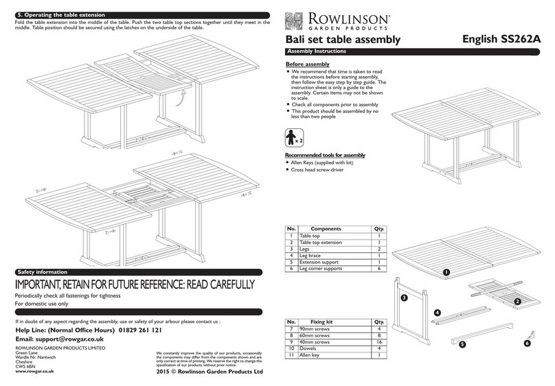
Rowlinson Garden Products Bali SS262A User manual

Rowlinson Garden Products

Rowlinson Garden Products Bali SS262A User manual

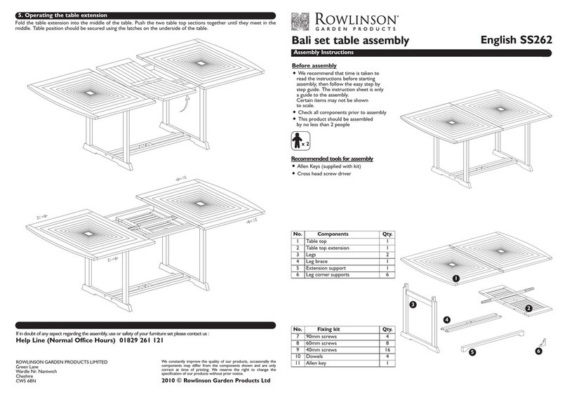
Rowlinson Garden Products Bali set User manual

Rowlinson Garden Products

Rowlinson Garden Products Bali set User manual

Popular Indoor Furnishing manuals by other brands

Dorel AMERIWOOD 9702083ST Assembly manual

Dorel

Dorel AMERIWOOD 9702083ST Assembly manual

Hailo Libero 3.0 Installation instruction

Hailo

Hailo Libero 3.0 Installation instruction

Steelcase 472 Assembly Directions

Steelcase

Steelcase 472 Assembly Directions

Somogyi Elektronic home SST 02 instruction manual

Somogyi Elektronic

Somogyi Elektronic home SST 02 instruction manual

JWA GRANT 716480001 Assembly instruction

JWA

JWA GRANT 716480001 Assembly instruction

Reshable MR11F0220 user manual

Reshable

Reshable MR11F0220 user manual

FMD Möbel BOLOGNE 668-003 Assembly instructions

FMD Möbel

FMD Möbel BOLOGNE 668-003 Assembly instructions

Costway KC55163 user manual

Costway

Costway KC55163 user manual

Armour Home Electronics alphason Boston AOC3282 quick start guide

Armour Home Electronics

Armour Home Electronics alphason Boston AOC3282 quick start guide

Baumax LUMENS 10 Assembling Instruction

Baumax

Baumax LUMENS 10 Assembling Instruction

Royalcraft W155-D92 Series Assembly instructions

Royalcraft

Royalcraft W155-D92 Series Assembly instructions

IKEA BJURSTA DINING TABLE 55x71x87" instructions

IKEA

IKEA BJURSTA DINING TABLE 55x71x87" instructions

Seaside Casual MAD 291 Assembly instructions

Seaside Casual

Seaside Casual MAD 291 Assembly instructions

Parker House RADIUS MRAD#832P Instruction Notice

Parker House

Parker House RADIUS MRAD#832P Instruction Notice

TRENDMANUFAKTUR TOKYO 02 Assembly instruction

TRENDMANUFAKTUR

TRENDMANUFAKTUR TOKYO 02 Assembly instruction

Customatic SQUIRE owner's manual

Customatic

Customatic SQUIRE owner's manual

Techni Mobili RTA-7337 Assembly instructions

Techni Mobili

Techni Mobili RTA-7337 Assembly instructions

versa INSERTO SEAT DOMINO Series Product Technical Specification

versa

versa INSERTO SEAT DOMINO Series Product Technical Specification

manuals.online logo
manuals.online logoBrands
  • About & Mission
  • Contact us
  • Privacy Policy
  • Terms and Conditions

Copyright 2025 Manuals.Online. All Rights Reserved.