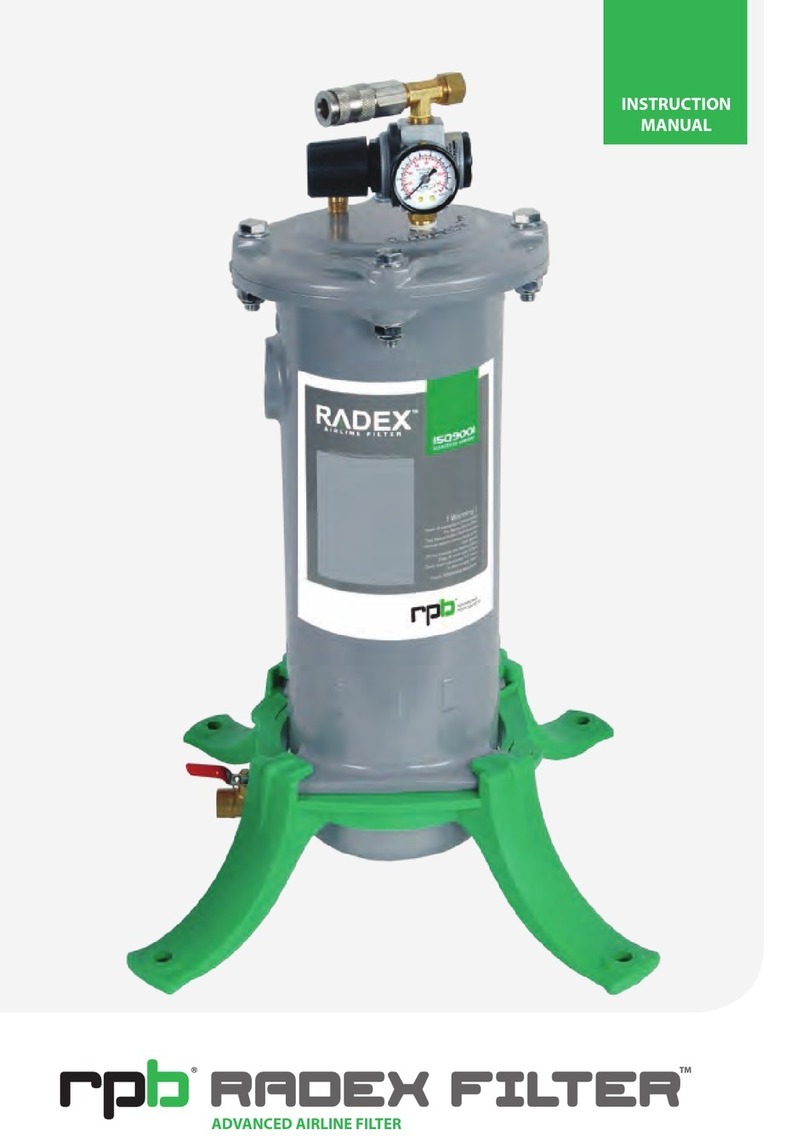
RPB radex User manual


!DANGER!
Do not connect the Radex Airline Filter to bottled air that does not
have a pressure reducing valve that will reduce the air pressure to
a maximum of 125 psig (860 kpa). Failure to comply with this
warning could cause the Radex Airline Filter to explode, causing
serious injury or death.
The Radex Airline Filter is designed to remove oil mist,
water vapour and particulates down to 0.5 micron from
breathing grade compressed air.
The Radex Airline Filter meets OSHA regulation 1910.94
(6) (i), requiring a trap and carbon filter be installed and
regularly maintained to remove objectionable odours,
as well as water, oil mist and other particulates.
The Radex Airline Filter also meets 1910.94 (6) (ii) by
providing a pressure reducing valve to reduce the pressure
to the requirements of supplied air respirators, providing
that the inlet pressure does not exceed 125 psig (860 kpa).
The Radex Airline Filter when fitter with micromist filter
Part No. 04-925 is designed to remove oil mist, water
vapour and particulates down to 0.001 micron complying
with ISO8573.1 Class 1 Air Quality.


4

5
BASE MOUNT
BASE MOUNT ASSEMBLY
The base mount can be attached in two positions, wall mount or floor mount. To connect the base
mount align the arrows on the base mount with the arrows on the filter, Fig 1.1 for floor mount, Fig
1.2 for wall mount. NOTE: The base mount will only fit in two positions, the arrows must align
before locking.
Turn the filter in a clockwise direction and lock into position. You will hear a click when the base
is in the final position.
Fig 1.1 Floor mount
locked
Fig 1.2 Wall mount
locked

6
04-900 ASSEMBLY
PRESSURE REGULATOR
To assemble the pressure regulator, thread the pressure gauge into the body (refer Fig 2.1) and
tighten. Connect the quick disconnect coupler and brass cap to the 3/8” tee and thread the 3/8”
tee into the top of the pressure regulator and tighten (refer Fig 2.2). It is recommended that the
regulator assembly is tightened before mounting onto the Radex Airline Filter. Use thread sealant
on all fittings.
Fit the completed regulator assembly onto the top of the Radex Airline Filter lid (refer Fig 2.3).
Once the regulator assembly has been tightened into position you can fit the pressure relief valve
and tighten (refer Fig 2.4)
! WARNING ! The pressure relief valve must be connected to protect the Radex Airline Filter from
over pressurizing.
Fig 2.1 Fig 2.2
Fig 2.3 Fig 2.4

7
ASSEMBLY
The Radex Airline Filter has a 1” NPT inlet. It is advised to connect a ball valve close to the inlet
so the unit can be shut off for servicing. Connect inlet fittings and tighten. Once the Radex Airline
Filter is completely assembled and connected to compressed air open supply line and check fitting
for any air leaks, tighten accordingly.
!WARNING! Do not over tighten fittings, as over tightening could crack the Filter Casting.
INLET CONNECTION
FITTING OPTIONAL MICRO MIST FILTER
To fit optional micro mist filter 04-925, first thread the reducing nipple 04-926 into the micro mist
filter then thread into the filter inlet and tighten, ensure the micro mist filter is positioned straight so
it drains moisture from the collection bowl. (fig. 31)
FIG 3.1

8
04-906 ASSEMBLY
SIX OUTLET MANIFOLD
To assemble the Six Outlet Manifold, firstly thread the 04-915 Pressure Gauge into the 04-965 6
Outlet Manifold and tighten (fig 4.1)
Thread all six 04-065 Couplers into the 04-065 Manifold and tighten (fig 4.2)
Thread the completed 04-964 Six Outlet Manifold in to filter lid and tighten (fig 4.3)
Thread the 04-916 Pressure Relief Valve into the lid and tighten.
!WARNING! The pressure relief valve must be connected to protect the Radex Airline Filter from
over pressurizing.
Fig 4.1 Fig 4.2 Fig 4.3
Fig 4.4 Fig 4.5

9
04-906 ASSEMBLY
SUPER HIGH FLOW REGULATOR ASSEMBLY
Thread the 04-963 Pressure Gauge and 04-966 1” NPT Connector into the 04-962 Super High
Flow Regulator and tighten. (fig 4.6)
Now thread the completed Regulator into the INPUT port on the body of the Radex Filter Unit
and tighten.
Check ALL fittings and connections are tight.
YOUR FILTER IS NOW READY FOR USE.
Note:
If the pressure gauge on the Super High Flow Regulator and the pressure gauge on the
Manifold are reading more than 10psi apart, your cartridge is blocked and needs replacing.
Refer to your respirator instruction manual for pressure ranges for your respirators, increase the
pressure according to the number of operators.
Fig 4.6 Fig 4.7

10
OPERATION
AIR PRESSURE
AIR TEMPERTURE
AIR QUALITY
AIR CONNECTIONS
The air pressure supplied to the Radex Airline Filter should not exceed 125psi (860 kpa).
When setting the outlet pressure using the pressure regulator refer to your respirator instruction
manual to set the correct air pressure.
The Air supplied to the Radex Airline Filter should not exceed 140 degrees Fahrenheit
(60 degrees Celsius). Do not connect the Radex Airline Filter directly to the compressor outlet
manifold.
The Radex Airline Filter does not remove carbon monoxide and other toxic gases from the
breathing air supply. A Radex carbon monoxide monitor 08-200 must be used at all times.
Supplied air passing through this Radex Airline Filter must meet the requirements of Grade D.
EN12021 or AS/NZS 1715 refer to your relevant authorities for copies of these standards.
Regular tests of the compressed air must be carried out to ensure it meets the requirements for
breathable air.
Connect air fittings that meet the requirements of OSHA for respirable air. The inlet thread size is
1” NPT. All connections should be sealed using liquid thread sealant. If the Radex Airline Filter is
hard piped an isolation valve must be used to enable depressurisation for servicing.

11
Shut off the air supply to the Radex Airline Filter and drain all air from the body by opening
the drain tap.
Remove the bolts from the lid and separate the lid from the body.
Remove the cartridge and dispose in an appropriate disposal area.
Clean the inside of the filter body to remove any contaminants, do not clean with volatile
chemicals.
Insert a new filter cartridge and reassemble the lid, tighten the bolts in the pattern drawn in
(Fig 4.1) tighten to 10ft/lb torque.
Fig 4.1
Record the date on the sticker supplied with the filter cartridge and place on to the Radex
Airline Filter.
1.
2.
3.
4.
5.
6.
The filter cartridge should be inspected weekly or more often depending on usage and the
conditions of the air system in which the Radex Airline Filter is installed. The filter cartridge should
be replaced after a period of 3 months based on a 40 hr week. The filter cartridge must be replaced
immediately if the following exist:
• The presence of odour and or tastes in the air being supplied to the respirator.
• Presence of moisture at the outlet fittings.
• Large pressure drop across the filter.
MAINTAINENCE
FILTER CARTRIDGE REPLACEMENT

12
Water will accumulate in the filter tank, this should be drained by opening the ball valve. This
should be done each day. In very humid climates or if there is large amounts of water in the air
supply it is recommended to leave the ball valve partially open to bleed the moisture.
When fitted with auto drain assembly (04-924) moisture will automatically drain from the unit as
required. It is recommended that the auto drain is rinsed in water to keep clean and free of
particles which could cause blockages.
The Radex Airline Filter lid bolts should be checked to ensure that they are tight. The lid bolts
(04-920) should be replaced when replacing the filter cartridge.
The recommended tightness for the lid bolts is 10ft.lbs. Check the orings (04-919) and replace if
damaged.
MAINTAINENCE
DRAINING MOISTURE
LID BOLTS, ORINGS

13


Other manuals for radex
1
Table of contents
Other RPB Water Filtration System manuals
Popular Water Filtration System manuals by other brands

Coleman
Coleman FlowClear 90355E owner's manual

Chungho
Chungho Whi Caffe Water Purifier New 700 user manual

Watts
Watts WQT4RO11-50 Installation, operation and maintenance manual

JNS Aquaria
JNS Aquaria FR-1ES installation guide

ASI
ASI TG-95-0400 Replacement instructions

Frizzlife
Frizzlife PD600-TAM3 owner's manual