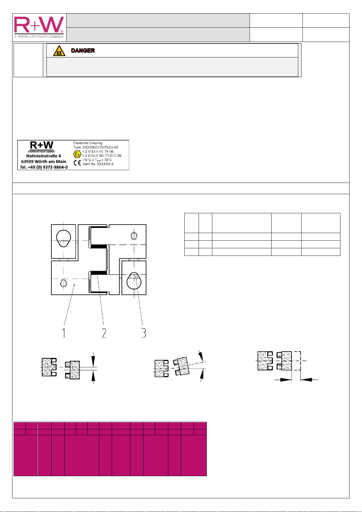
EK2 Elastomer Coupling series 20 to 800
Safety-conscious working
All persons carrying out work concerning installation, commissioning, operation and maintenance must read this manual in full and
attentively and observe all the safety rules and warnings described.
•Plans / Projectiles:
oPlanning the use
•Craftsmen / operators:
oImplementation of planned activities
oOperation of the elastomer coupling
Keep this guide in an appropriate place. Provide these instructions with the elastomer coupling during an operator change.
Intended use in compliance with Directive 2014/34/EU (ATEX)
Only EK2 elastomer couplings with elastomer insert made of black, conductive TPU material with
marking D at the end of the product code are suitable for use in potentially explosive areas:
The intended use of the EK2 elastomer coupling is:
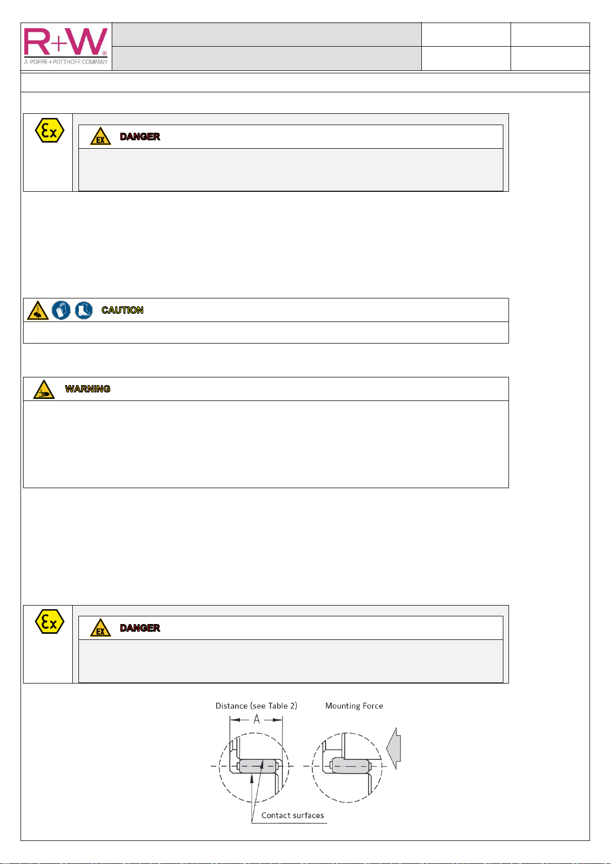
Torque transmission between 2 horizontal shafts with offset. The coupling equals axial, lateral
and angular offset up to the values specified in the technical data.
Use in zones 1, 2, 21, 22 of subgroups IIC and IIIC.
The evaluation and labelling are carried out in accordance with DIN EN ISO 80079-36 and 37.
The operating parameters specified in this operating manual must be adhered to and the prescribed
conditions for installation, assembly, initial commissioning, operation, maintenance and dismantling
must be considered.
According to Directive 2014/34/EU (ATEX), the EK2 elastomer couplings are treated as a device that
transmits energy and has its own ignition sources. Accordingly, they must be marked with CE and
receive an EU declaration of conformity as a device.
The electrical conductivity of the TPU material prevents the electrostatic charging of the elastomer
insert. This prevents the formation of sparks by the elastomer insert.
Incorrect elastomer material can lead to a charge of the elastomer insert, which can lead to an
effective source of ignition and thus to an explosion. Operate the EK2 elastomer coupling for
potentially explosive areas only with electroconductive, black elastomer inserts.
Explanation of the EC Machinery Directive 2006/42/EC
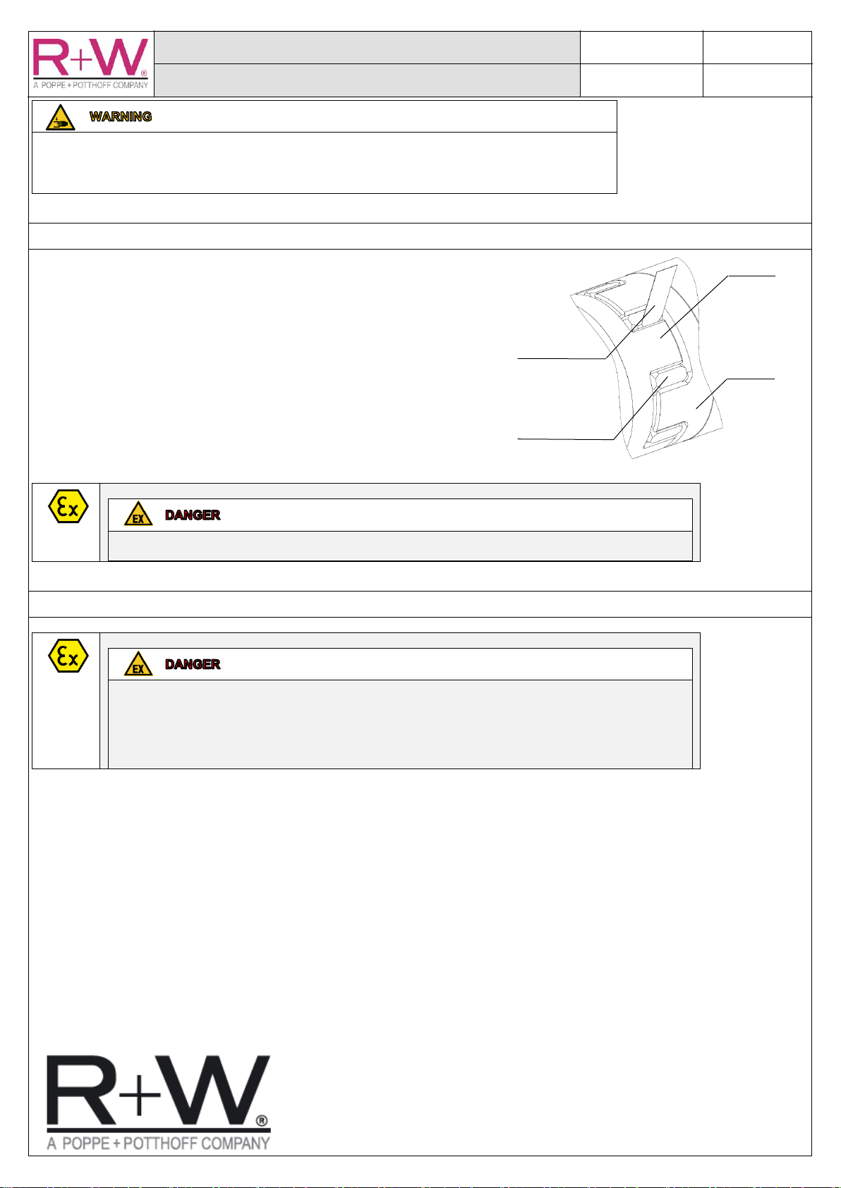
Due to its elastomer segments, the EK2 elastomer coupling is an elastic coupling. As an elastic
coupling, it is a component for installation in different machines with different applications.
In accordance with the Machinery Directive 2006/42/EC and the guideline for the application of the
Machinery Directive 2006/42/EC of the European Commission Enterprise and Industry, 2nd edition June
2010, general editor Ian Fraser, EK2 elastomer coupling is as a flexible coupling a component and
therefore no machine and no incomplete machine. As a component within the meaning of the Machinery
Directive, the EK2 elastomer coupling is not to be CE marked, receives neither CE declaration of
conformity nor incorporation or serial number, and is therefore not covered by the Machinery Directive.
Conformity to Directive 2006/42/EC can only be declared as a whole after it has been installed in a
machine by the manufacturer of that complete machine. Information on safe installation, safe
commissioning and safe operation can be found in this manual. Commissioning is prohibited until the
requirements of the Machinery Directive are met by the installer through or after integration into the final
product.
Coupling protection
The installer shall provide suitable coupling protection in order to prevent contact between personal
body parts or the retraction of parts with the rotating EK2 elastomer coupling. The cover housing must
be sufficiently robust as it is intended to protect the coupling from falling objects. Openings should
ensure a possible heat dissipation.