RS IDM67 User manual

INSTRUCTION MANUAL
IDM67 DIGITAL MULTIMETER
EN IT DEFR JP

1
IDM67
DIGITAL MULTIMETER
INSTRUCTION MANUAL

2

3
INTRODUCTION
1-1 Unpacking and Inspection
Upon removing your new Digital Multimeter from its packing, you should have the following items:
1. Digital Multimeter.
2. Test lead set (one black, one red).
3. Instruction Manual.
4. Holster.
1-2 Meter Safety
Terms as Marked on Equipment
ATTENTION —Refer to Manual.
DOUBLE INSULATION —Protection Class II.
DANGER —Risk of electric shock.

4
Symbols in this Manual
This symbol indicates where cautionary or other information is found in the manual.
Fuse
<Battery
1-3 Front Panel
Refer to Figure 1 and the following numbered steps to familiarise yourself with the meter's front panel controls and
connectors.
1. Digital Display —The digital display has a 3200 counts LCD readout with 65 segments analog bar graph, auto
polarity, decimal point, <, =, DC, AC, ;, I, and Unit annunciators.
2. Rotary Switch —Selects the desired function and range.
3. COM Input Terminal —Ground input connector.
4. VΩInput Terminal —Positive input connector for Volts, Ohms and Diode measurements.

5
5. µA mA Input Terminal —Positive input connector for current measurements. (up to 300mA).
6. A Input Terminal —Positive input connector for current measurements. (up to 10A)
7. Function Switch (Blue) —Press the switch to measure AC Current or DC Current in the current mode, or to
measure continuity or diode check in ;/9mode.
8. Reset Switch - The meter can be turned back on by pushing "RESET" key switch.
9. Hold Switch - This switch is used to hold measured values for all functions. When pressed the "=" annunciator
is displayed. Conversions are made but the display is not updated.
10. Range Switch (Manual Range) –The "Range" switch is pressed to select manual ranging and to change
ranges. When the "Range" switch is pressed once, the "RANGE" annunciator on the LCD disappears. Press the
"Range" switch to select the appropriate range to be used. Press the "Range" switch and hold for 2 seconds to
return to Auto-ranging.

6
Figure 1

7
SPECIFICATIONS
2-1 General Specifications
Display : The Liquid Crystal Display (LCD) has a maximum reading of 3200, and 65 segments bar graph.
Polarity Indication : Automatic, positive implied, negative indicated.
Overrange Indication : "OL" or "-OL".
Low Battery Indication : "<" is displayed when the battery voltage drops below operating voltage.
Sampling : 2 times/sec for digit readout. 12 times/sec for analog bar graph readout.
Auto Power Off : Approximately 10 minutes unless the measured value changes within this time.
Temperature Coefficient : 0.15 x (Specified accuracy) / °C, < 18°C or > 28°C.
Power Requirements : Alkaline 1.5V x 2.
Battery Life : Alkaline 900 hours.
Dimensions (HxWxD) : 66mm x 155mm x 34mm, without holster.
85mm x 165mm x 40mm, with holster.
Weight (including battery) : 240 gms, without holster.
360 gms, with holster.
Supplied Accessories: Test leads, battery (installed), operator's manual and holster.

8
2-2 Environmental Conditions
For indoor use.
Maximum Altitude : 2000m.
Installation Category : IEC 1010, 600V CAT II, 300V CAT III.
Pollution Degree : 2
Operating Ambient : 0°C to 50°C, 0 to 80% R.H.
Storage Temperature : -20°C to 60°C, 0 to 80% R.H. with battery removed from meter.

9
2-3 Electrical Specifications
Accuracy is ± (% reading + number of digits) at 23C ± 5C less than 80% R.H.
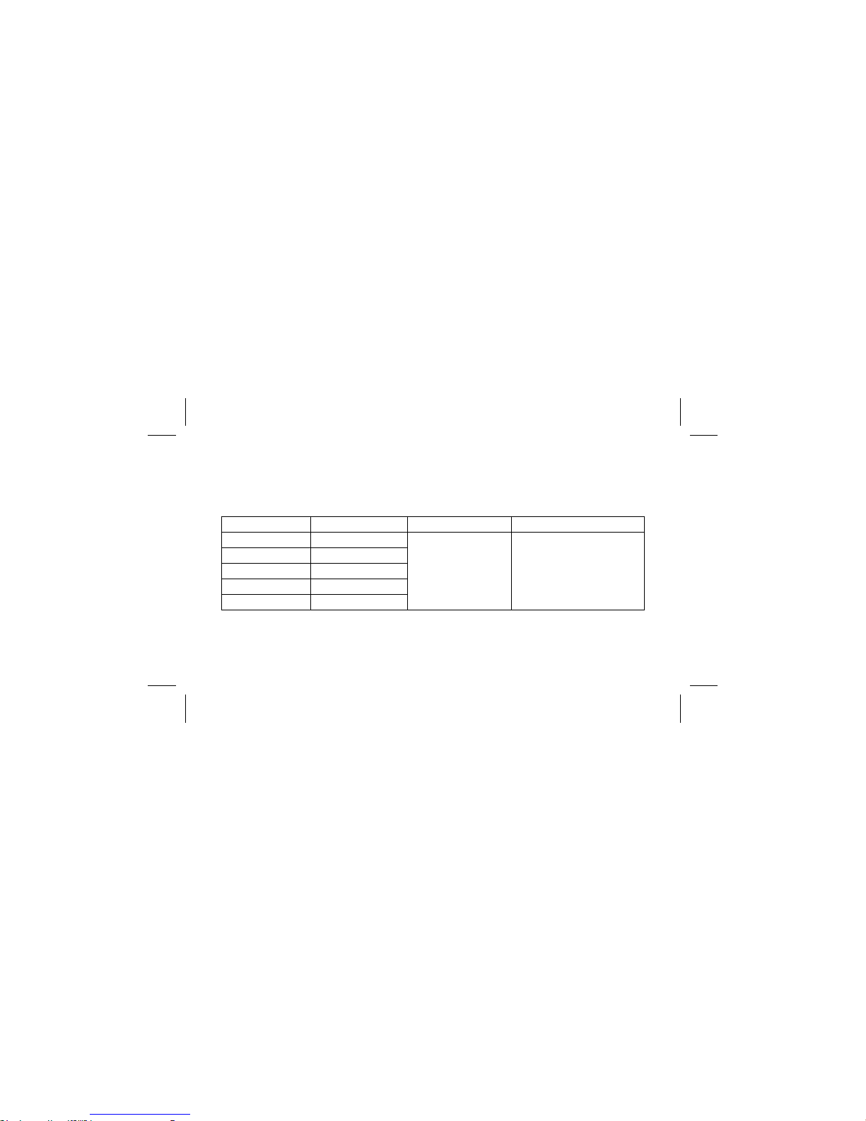
(1) DC Volts
Range Resolution Accuracy Over voltage protection
300mV 100µV
±(0.7%reading + 2digits) 600Vd.c. or 600Va.c.rms
3V 1mV
30V 10mV
300V 100mV
600V 1V
Input Impedance: 10MΩ.

10
(2) AC Volts
Range Accuracy Over voltage protectionResolution
3V ±(1.7%reading + 5digits)
600Vd.c. or 600Va.c.rms
1mV
30V
±(1.7%reading + 5digits)
40Hz to 500Hz
10mV
300V 100mV
600V 1V
* Frequency Response : 40Hz ~ 300Hz for 3V Range.
AC Conversion Type : Average Sensing rms indication.
Input Impedance : 10MΩ// less than 100PF.

11
(3) DC Current
Range Resolution Accuracy Voltage Burden
300µA 0.1µA 200mV max
±(1.2%reading + 2digits)
3mA 1µA 2V max
30mA 10µA 200mV max
300mA 100µA 2V max
10A 10mA ±(2.5%reading + 5digits) 2V max
Overload Protection : 0.5A/250V fast for µA/mA input.
10A/250V fast for A input.

12
(4) AC Current
* Frequency Response : 40Hz ~ 500Hz.
Overload Protection : 0.5A/250V fast for µA/mA input.
10A/250V fast for A input.
Range Resolution Accuracy Voltage Burden
300µA 0.1µA 200mV max
±(1.7%reading + 4digits)
3mA 1µA 2V max
30mA 10µA 200mV max
300mA 100µA ±(2.0%reading + 4digits) 2V max
10A 10mA ±(2.9%reading + 7digits) 2V max

13
(5) Resistance
Range Resolution Accuracy Overload Protection
300Ω0.1Ω±(1.2%reading + 4digits)
600Vd.c. or 600Va.c. rms
3KΩ1Ω
±(0.9%reading + 2digits)
30KΩ10Ω
300KΩ100Ω
3MΩ1KΩ±(1.2%reading + 3digits)
30MΩ10KΩ±(2.5%reading + 5digits)
* Open Circuit Voltage: 1.3V approx.

14
(6) Diode Check and Continuity
Range Resolution Accuracy Max. Test Current Max. Open
Circuit Voltage
;91mV ±(1.5%reading + 5digits) 1.5mA 3.3V
*For 0.4V ~ 0.8V.
Overload Protection: 600V DC/AC rms max.
Continuity: Built-in sounder will operate when resistance is less than 50Ω.
(7) Auto Power Off
The meter will automatically shut itself off approximately 10 minutes after power on unless the value being measured
changes within this time.
The meter can be turned back on by pressing "Reset" key switch.
(8) Sounder Guard
The sounder will operate if the test lead is connected to the /µA/mA/(A) input terminal, when the rotary function
selector is not in the /µA/mA/(A) positions.

15
OPERATION
This instrument has been designed and tested in accordance with IEC Publication 1010, Safety Requirements for
Electronic Measuring Apparatus and has been supplied in a safe condition. This instruction manual contains some
information and warnings which must be followed by the user to ensure safe operation and to retain the instrument in
safe condition.
3-1 Preparation and Caution before Measurement
1. Allow at least 30 seconds after switching on before taking measurements.
2. When the rotary function selector is changed during measurement, be sure to do so only after removing the test
leads from the equipment.
3. If the equipment is used near noise generating equipment, be aware that the display may become unstable or indicate
large errors.
4. Maximum rated voltage to earth for voltage and current measurements terminals is 600V AC/DC CAT II.

16
TEST EQUIPMENT RISK ASSESSMENT (UK RECOMMENDATION)
Users of this equipment and/or their employers are reminded that Health and Safety legislation require them to carry
out valid risk assessments of all electrical work so as to identify potential sources of electrical danger and risk of
electrical injury such as from inadvertent short circuits. Where the assessments show that the risk is significant then
the use of fused test leads constructed in accordance with the HSE guidance note GS38 "Electrical Test Equipment
for use by Electricians" should be used.
3-2 Voltage Measurements
1. Connect the red test lead to the "VΩ" input terminal and the black test lead to the "COM" terminal.
2. Set the rotary function selection to ACV or DCV position.
3. Connect the test leads to the device to be measured.
4. When the input is over-ranged the “OL” is displayed.
5. "Warning : Do not exceed 600Vd.c. or 600Va.c. limits stated in the specification".

17
WARNING
TO AVOID ELECTRIC SHOCK HAZARD, OR DAMAGE TO THE METER, DO NOT ATTEMPT TO MEASURE
VOLTAGES THAT MIGHT EXCEED 600 V d.c. OR 600 V a.c.rms. DO NOT APPLY MORE THAN 600V d.c. OR
600V a.c. RMS BETWEEN THE COMMON INPUT TERMINAL AND EARTH GROUND.
3-3 Resistance Measurement
1. Connect the red test lead to the "VΩ9" terminal and the black test lead to the "COM" terminal.
2. Set the rotary function switch to the "Ω" position .
3. For correct reading, ensure that there is no voltage present across the device being tested.
4. Connect the test leads across the resistor to be measured. In order to ensure the best accuracy in measurement
of low resistance, short the test leads before measurement and note the test lead resistance. It is necessary to
subtract the resistance of the test leads from the displayed reading.

18
3-4 Continuity Check by Sounder
1. Connect the red test lead to the "VΩ" terminal and the black test lead to the "COM" terminal.
2. Set the rotary function switch to ";" position.
3. Connect the test leads to the circuit to be measured. The sounder will operate if the resistance of the circuit measured is
lower than 50Ω.
4. The sounder may operate when the instrument is first switched on in the continuity mode and all the LCD segments are
displayed.
3-5 Diode Check
1. Set the rotary switch to the ";" position.
2. Connect the black test lead to the "COM" terminal and the red lead to the "VΩ" input terminal.
3. Connect the test leads to the diode. Normally the forward voltage drop of good silicon diode is between 0.4V to
0.9V. If the diode under test is defective, "000" (short circuit) or "OL" (non-conductance) is displayed.
Reverse Check of Diode: If the diode under test is good "1" is displayed. If the diode under test is defective "000" or
other values will be displayed.

19
3-6 Current Measurement
WARNING : DO NOT CONNECT THE METER LEADS TO A VOLTAGE GREATER THAN 250V AC/DC
WHEN PERFORMING CURRENT MEASUREMENTS
1. Connect the red test lead to "µA/mA" terminal and the black test lead to the "COM" terminal or use the "A" and "COM"
terminals in the "A" range.
2. Set the rotary function selector rotary switch to "µA" or "mA" or "A".
3. Measurement of AC current can be performed by pressing the "AC/DC" switch.
4. Connect the test leads to the circuit to be measured.
Table of contents
Other RS Multimeter manuals