manuals.online logo
Brands
  1. Home
  2. •
  3. Brands
  4. •
  5. RSG
  6. •
  7. Automobile Accessories
  8. •
  9. RSG Standby S-HAL06 User manual

RSG Standby S-HAL06 User manual

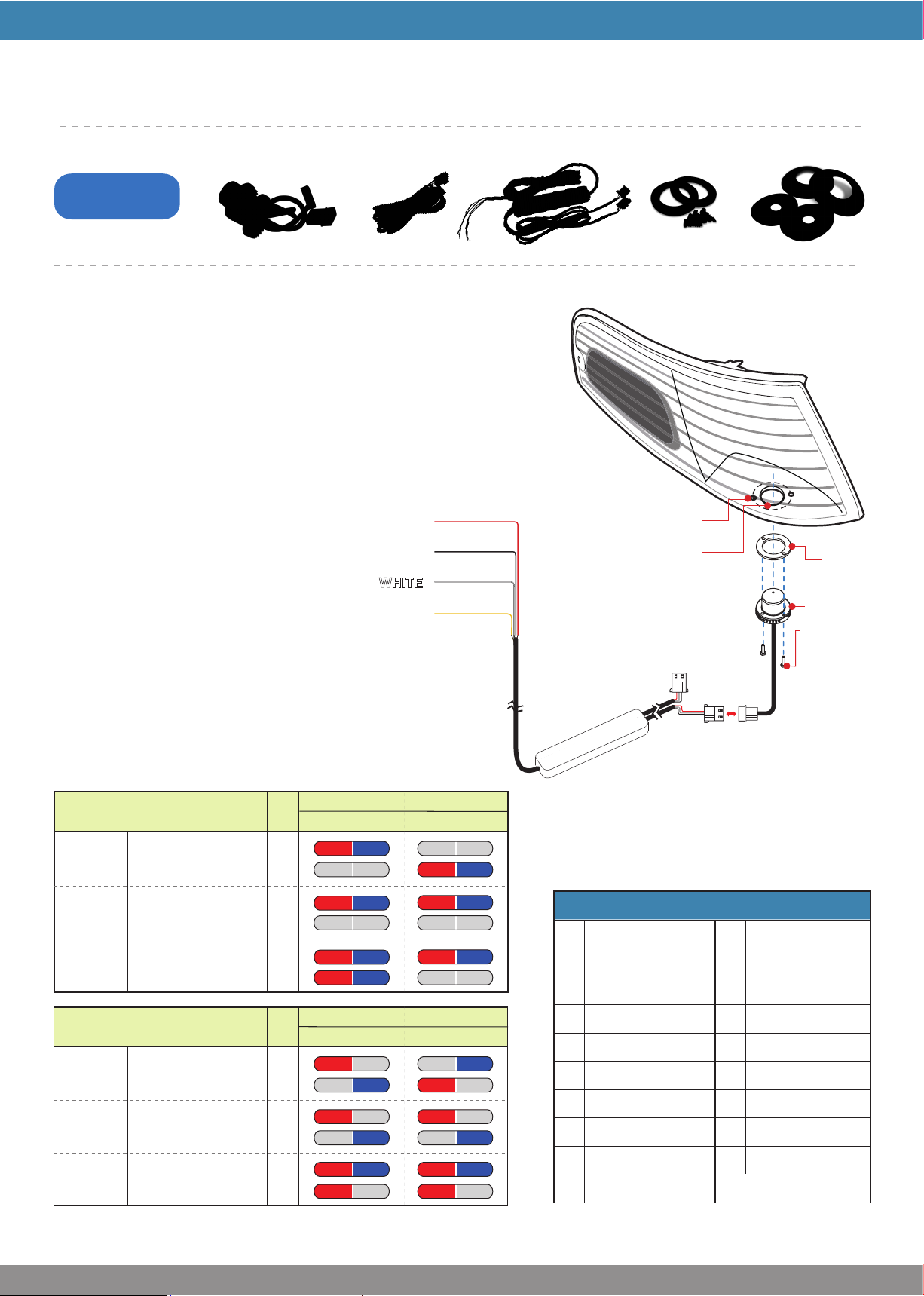
To +VDC (fuse @2A) for Color1 activation........................RED
To Chassis Ground.......................................................BLACK
To +VDC (fuse @2A) for Color2 activation...................WHITE
For Synchronization & Flash Patterns.......................YELLOW
Connect YELLOW wires of all Kits together for synchronization
*All kits must be set at the same pattern
For Simultaneous or Split Flash (single head):
1. Apply +VDC to RED and YELLOW wires simultaneously to enter Mode
selection; lighthead will display single flash.
2. Remove YELLOW wire from +VDC and momentarily apply to +VDC to change
Mode: Mode1 = Simultaneous Flash, Color1 and Color2 LEDs flash together.
Mode2 = Split Flash, Color1 LEDs alternate with Color2 LEDs.
(default)
Flash
Patterns
#1~9
Flash
Patterns
#10~17
Flash
Pattern
#18
Color1&2flashtogether,
Head1alternate Head2
Color1&2flash together,
Head1&2flashtogether
SteadyHalf
Mode1 (Simultaneous Flash)
(Suitable for Single-Color Heads) Color1Color2 Color1Color2
1st
Flash
Mode2 (Split Flash)
(Suitable for Split-Color Heads) Color1Color2 Color1Color2
Flash
Patterns
#1~9
Color1 alternate Color2
1st
2nd
1st
2nd
1st
2nd
off off
off off
Flash
Patterns
#10~17
Color1 flash together, off off
off off
Color2 flash together off off
Flash
Pattern
#18
SteadyHalf on on on on
on on
Head1 Head2
on
on
on
on
on
on
on
on
Flash
2nd
1st
2nd
1st
2nd
off
off
off
off
on on on on
on on
Head1 Head2
on
on
on
on on on
on on
offoff offoff
offoff
GASKET x 2pcs
SCREW x 4pcs
LIGHTHEAD x 2pcs
USER MANUAL
UNDERCOVER LED KIT
CONTENTS
6LED KIT
w/ Split Color
FLASHER & CABLEEXTENSION CABLE
LIGHT ASSEMBLY INSTALLATION
1. Remove the Corner/Head/Tail light from vehicle.
2. Select location to mount lighthead.
3. Drill 1 inch diameter hole to the light assembly.
4. Insert lighthead into hole and rotate to achieve optimum effect.
5. Secure lighthead with supplied sheet metal screws.
6. Apply silicone (user-supplied) for better seal.
WARNING: Do NOT cover heat sink with silicone. It may cause
damage to the product and void warranty.
NOTE: This unit may not be factory set at FP# 1.
For Flash Pattern change, momentarily apply +VDC
to YELLOW wire: ∙ once for next pattern
∙ quickly three times for reset
2
3
4
5
6
8
9
10
11
12
14
1
Single (split)
Double (split)
Quad (split)
Quint (split)
Mega (split)
Random
Single-Quad (split)
Single H/L(split)
Single (all)
Double (all)
Quad (all)
Ultra (split)
Mega (all)
Ultra (all)
Single-Quad (all)
Single H/L (all)
Steady Half
Quint (all)
7
13
15
16
17
18
Steady All19
Flash Patterns
131220F10
OPERATIONS
Mounting screw holes
1 inch dia.hole
Supplied sheet
metal screw
Gasket
Lighthead
VEHICLE
CORNER LIGHT
ASSEMBLY
FLANGE OPTION x 2pcs
FOAM x 2pcs
NOTE: Lighthead mounting location
may vary depending on the design of
the vehicle light assembly.
to lighthead
FLANGE MOUNT INSTALLATION (for kits with Flange option only)
STROBE
POWER SUPPLY
In this configuration, existing strobe extension cables are used to facilitate installation.
WIRING TO EXISTING STROBE CABLES
STROBE BULB
EXTENSION CABLE
(already in vehicle)
NOTE: Wire colors of LED Kit do not need
to match wire colors of extension cables.
2. Connect LED Kit
connectors to strobe
extension cables.
1. Disconnect strobe
extension cables from
strobe power supply. 3. Remove & Disconnect Strobe
bulbs from extension cables.
4. Insert & Connect LED Ligtheads
to strobe extension cables.
WARNING: Do not connect LED lighthead directly to strobe
power supply. It will cause damage and void the warranty.
to (+)
to GND
CONTROLLER
NOTE: Position lighthead so that LEDs are facing the desired direction.
WARNING: Make sure to use the foams when mounting lightheads.
Supplied sheet
metal screw
Mounting
Flange
Lighthead
Foam
Mounting screw holes
VEHICLE
MOUNTING
SURFACE
to flasher
1.89” (48mm)
Wire hole
0.78” (22mm)
1. Use mounting flange to mark wire and screws holes to drill.
2. Drill marked holes accordingly.
3. Insert lighthead pigtail into wire hole.
4. Place foam, lighthead, and flange in line with the mounting
holes, and secure with supplied sheet metal screws.
The Flange Mount Option enables surface mounting of lightheads
to provide optimum light output to the critical intersection angles.
vehicle top view

This manual suits for next models

1

Other RSG Automobile Accessories manuals

RSG MCS-16 User manual

RSG

RSG MCS-16 User manual

RSG Standby S-PAL06 User manual

RSG

RSG Standby S-PAL06 User manual

RSG CVS-012 User manual

RSG

RSG CVS-012 User manual

Popular Automobile Accessories manuals by other brands

SSV Works DF-F65 manual

SSV Works

SSV Works DF-F65 manual

Thermo King UT-800 Operator's manual

Thermo King

Thermo King UT-800 Operator's manual

SCA 195 Assembly instructions

SCA

SCA 195 Assembly instructions

CoverCraft Form-Fit Use and care instructions

CoverCraft

CoverCraft Form-Fit Use and care instructions

eRapta AYX103 Installation and operation guide

eRapta

eRapta AYX103 Installation and operation guide

Thule 39 manual

Thule

Thule 39 manual

Zoombak Advanced GPS Car Locator installation guide

Zoombak

Zoombak Advanced GPS Car Locator installation guide

HAUL MASTER 94564 Assembly and operating instructions

HAUL MASTER

HAUL MASTER 94564 Assembly and operating instructions

Big Country 372901 installation instructions

Big Country

Big Country 372901 installation instructions

ATD Tools SPI-77101 user manual

ATD Tools

ATD Tools SPI-77101 user manual

Steinhof L-113 FITTING AND OPERATION MANUAL

Steinhof

Steinhof L-113 FITTING AND OPERATION MANUAL

Thule Rapid 1451 Fitting instructions

Thule

Thule Rapid 1451 Fitting instructions

Thule HULL-A-PORT 835xt manual

Thule

Thule HULL-A-PORT 835xt manual

CBE MTT user manual

CBE

CBE MTT user manual

Retrax EQ quick start

Retrax

Retrax EQ quick start

Westfalia 305 407 300 107 Installation and operating instructions

Westfalia

Westfalia 305 407 300 107 Installation and operating instructions

STL Z-6 instruction manual

STL

STL Z-6 instruction manual

Warrior Products 4500-2 Assembly and installation

Warrior Products

Warrior Products 4500-2 Assembly and installation

manuals.online logo
manuals.online logoBrands
  • About & Mission
  • Contact us
  • Privacy Policy
  • Terms and Conditions

Copyright 2025 Manuals.Online. All Rights Reserved.