RSSI RSS-3000 Series User manual

Installation Manual
March 3, 2022
Page 2 of 25
Contents
Page 3 General
Page 3 Before you Begin
Page 3 Hazard Alert Message and Symbol
Page 4 How to Obtain Factory Support
Page 4 General Safety
Page 4 Barrier Description
Page 5 Barrier Installation –A Five Step Process
Page 5 Step One –Excavate
Page 6 Step Two –Placing Rebar and Form Boards
Page 6 Step Three –Barrier Conduit Connections
Page 7 Step Four –Concrete
Page 7 Step Five –Drilling and Mounting of Buttresses
Page 9 Step Six –Conduit, Wire, and Termination of Controls
Attachments
Page 16 1. Safety Loop Set-Up
Page 17 2. Servo Drive Set-up
Page 19 3. Vehicle Detector Loop Installation
Page 22 4. Traffic Light Installation
Page 23 5. Commissioning Checklist

Installation Manual
March 3, 2022
Page 3 of 25
INTRODUCTION
This manual provides Installation Procedures for the RSS-3000 series electric drop beam vehicle barrier system
for Integrators/Contractors. It is NOT intended to be all encompassing and is based on “typical” installations.
Afterreviewofthismanual,werecommendaconferencecallwiththeRSSIfactorytodiscussquestionsregarding
procedures that may require further clarification. RSSI is a barrier manufacturer; on questions related to civil
issues specific to a particular jobsite, Integrators/Contractors should refer to the Architectural Firm that designed
the project or a licensed Civil Engineer familiar with the local site conditions and requirements.
GENERAL
The RSS-3000 Drop Beam Barrier is a modern "best-of-breed" electrically operated, retractable, Drop
Beam vehicle barrier that, when properly configured, can operate with a continuous duty cycle in all
climates with minimal maintenance and expense. An Allen-Bradley MPAI series IP-67 servo
electromechanical actuator with manual override and rapid reverse smoothly and quietly rotates an
arresting element to an above ground position of 42" without obstructing line-of-sight vision
BEFORE YOU BEGIN
●Read and understand all instructions and procedures before you begin to install
components.
●Read and observe all Warning hazard alert messages in this publication. They provide
information that can help prevent serious personal injury, damage to components, or
both.
●Follow your company’s safety guidelines, to include lockout procedures.
●Use the proper tools when required to help avoid serious personal injury and damage to
components.
●After review of this manual, we recommend a conference call with the RSSI factory to
discuss any questions regarding procedures we may not have addressed or that require
further clarification.
HOW TO OBTAIN ADDITIONAL FACTORY SUPPORT
If you have any issues or questions, on-site integrator/contractor personnel are highly encouraged
to contact RSSI’s Service department. WE CAN HELP YOU! Normal office hours are 7:00
AM CST - 3:00 PM CST Monday -- Friday. After hours support is available with prior
coordination
Telephone
Email
+1 (850) 871-9300
Optional Installation Items
RSSI can provide optional items that will help make the installation process easier for your
Team. Items include Rebar Cages with welded mats, correct Anchor Bolts and hardware, Epoxy,
Epoxy Applicator, and Bolt Template for Receiving Buttress. Please contact RSSI for more
details.

Installation Manual
March 3, 2022
Page 4 of 25
HAZARD ALERT MESSAGE AND SYMBOLS
WARNING
A Warning alerts you to an instruction or procedure that you must follow exactly to avoid
serious personal injury and damage to components.
CAUTION
A Caution alerts you to an essential installation or maintenance procedure or statement,
which, if not strictly observed, could result in damage to the system, equipment or injury.
NOTE
A Note alerts you to an essential installation or maintenance procedure, condition, or
statement.
GENERAL SAFETY
Personnel MUST comply with thefollowing important safetyinstructions DURING installation activities forthe
RSS-3000 series electric drop beam vehicle barrier system.
●Read and comply with all safety rules in this manual.
●A fully trained installation person must perform all start-up work.
●Do not operate this equipment when you are distracted or under the influence of drugs,
alcohol or medication causing diminished control.
●Prior to start-up of the RSS-3000 series electric drop beam vehicle barrier system, all
electrical connections to the barrier will be isolated (disconnected) IAW local Lock Out
Procedures.
●Never operate this equipment when a vehicle, person or any obstruction is in the way of
full operation of the RSS-3000.
BARRIER DESCRIPTION
●RSS-3000 Series Electric Drop Beam consist of all steel construction and hot dip
galvanized frame, post, and beams. Main buttress is 3.5 feet wide and 6 feet long, and
receiving buttress is 3 feet wide and 3 feet long. Beam lengths can offer protection for
clear openings from 12 to 20 feet wide.
●Beam Dimensions are 3/8” steel tubing, 3 inches wide by 6 inches tall and Beam Height
is 42”inches to the top of beam from drive surface. Operating System is Servo EM
Actuator technology and a Spring Assist Assembly. Standard Operation is less than 8
seconds. Operating Temperatures: Operational speeds are constant in temperatures
ranging from -20 degrees to 200 degrees Fahrenheit with the use of heat on the
operating systems.
●The Drop Beam Height when down is 42” and opens to a full 90°. The weight of the
barrier depends upon the length of beam unit purchased.

Installation Manual
March 3, 2022
Page 5 of 25
BARRIER INSTALLATION –A Five Step Process
NOTE
Before you begin, you will need the following available on site prior to installation:
▪Equipment for excavation, soil compaction, removal and disposal of spoils
▪Concrete placing and finishing tools
▪#5 steel re-bar
▪3000 PSI (minimum) Mix Concrete
▪Equipment capable of lifting and setting the RSS-3000 series barrier in place
Step One –Excavate
●The first step is to excavate the existing roadway to a dimension of the appropriate
buttress size. Refer to barrier description above or your site specific drawings.
NOTE:Rebar Length and Yardage of Concrete provided here are estimates done by RSSI.
You should always finalize material count using prints pertaining to that certain job.
Buttress
Excavate Area
(W x L x H)
Rebar Type #5
Concrete
(3000 PSI min.)
Pivot End
4’ x 7’-3” x 3’-6”
130 feet
3 yards
Receiving End
4’ x 5’ x 3’-6”
100 feet
2.2 yards
Excavation, Concrete, and Rebar details
NOTE: Ensure barrier placement according to the approved site plan to ensure road
crown, underground utilities and tie into associated passive knee walls or bollards is
taken into account.

Installation Manual
March 3, 2022
Page 6 of 25
Step Two –Placing Rebar and Form Boards
●Once the soil is compacted, place the # 5 rebar cage centered in the excavated area. Keep
in mind when placing rebar cage that it needs to be clear of the Anchor Bolts that will be
drilled in later. Form Boards to be placed on top of existing elevation to form the 6 inch
above ground base for the RSS-3000 Drop-Beam. Refer to Installation Drawings.
WARNING
Ensure Proper rebar placement according to the drawings. If not properly placed you will
have issues hitting rebar during bolt placement.
Step Three –Barrier Conduit Connections
RSS-3000 Drop Beam are fully operational and self-contained shipped from the factory ready to
install. Drop Beams require 1” Flex Conduit be installed on the Power J-Box and 1” Flex
Conduit be installed on the Control J-box onsite.

Installation Manual
March 3, 2022
Page 7 of 25
Step Four –Concrete
●Pour the concrete (3,000 psi minimum) around and inside the Rebar Cage and inside the
Form Boards. Be careful not to damage the electrical conduit. A light broom finish is
recommended. Allow sufficient time for concrete to harden before installing the RSS-
3000 unit.
Step Five –Drilling and Mounting of Buttresses
1. Once concrete has cured, verify that the foundations are leveled and at the same
elevation, with receiving buttress bolts cast in place.
2. Place the receiving buttress over the imbedded anchors and bolt it in place.
3. Place the main buttress and beam assembly on its foundation so that there is sufficient
clearance between the impact pin and the receiving buttress flange for the beam to be
able to rise. Center the beam in the receiving buttress cradle.

Installation Manual
March 3, 2022
Page 8 of 25
4. Once the main buttress is correctly positioned, install the epoxy anchors per installation
instructions and epoxy manufacturer’s requirements.
WARNING
You mayhavetoadjustActuatorusingthemanualdrivetoremoveretaining pin (Picabove)0,
pleaseensureyoudisengageoverdriveaftermanualfunctionis usedandbeforeoperatingbarrier.
Failuretodoso candamagetheActuator.
5. Carefully remove the retaining strap and safety pin from the hinged buttress.
6. The barrier can now be raised using the manual screw on the actuator if necessary. Be
sure to disengage the manual screw prior to operating the actuator electrically.

Installation Manual
March 3, 2022
Page 9 of 25
NOTE
Please refer to the manual screw operation instructions that are in the Maintenance Manual.
You can also contact a RSSItechnician by calling 850 -871- 9300 or email at
service@rssi.com .
WARNING
Failuretooperatethemanualscrewproperlywilldamagetheactuatorandvoidthewarranty.
Step Six –Conduit, Wire, and Termination of Controls
Conduit and Wire
●Rigid Metallic Conduit should be used when penetrating the foundation for the BCP
and where exposed to the elements.
●Electrical and Control Conduits will be run from the barrier into and out of Electrical
and Control J-box (quazite box) to the BCP. Use stranded wire.
●After conduit has been installed, move on to controls. BCP’s and BBP’s arrive
complete from the factory. Ensure all control wire and power wires from the barrier, to
the BCP, to the operator controls are labeled to expedite termination to the BCP.
●Fiber. The Fiber may need to be run from the BCP to the Fiber Converter Panel.
Ensure a qualified technician that can install, terminate, test, and certify Fiber is used.
●Electrical Power Cables should be sized by a Master Electrician or EE per N.E.C.
Code based on distance from BCP’s and BBP’s to barriers.
WARNING
ENSURE A QUALIFIED ELECTRICIAN TERMINATES THE ELECTRICAL
CONNECTIONS ACCORDING TO NATIONAL ELECTRIC CODE AND ANY
APPLICABLE LOCAL CODES.
Terminations
●All Ethernet terminations should be tested with Ethernet cable tester (TIA/EIA 568A
standard).

Installation Manual
March 3, 2022
Page 10 of 25
●All Multi-mode Fiber Optic cable should be terminated (Type ST Connectors)and tested by
a qualified fiber optic technician.
Electrical Terminations
1. If BBU is provided by RSSI, local commercial power (Typically 120/240 V) 1P 3 wire 30A is
wired to Battery Backup Panel (BBP) at MAIN CB-1 (L1 –L2, - Ground). If no BBU commercial
power will connect to Top of Main Disconnect Switch in Barrier Control Panel.
2. BBP transfers power to Barrier Control Panel (BCP) MAIN Disconnect Switch.
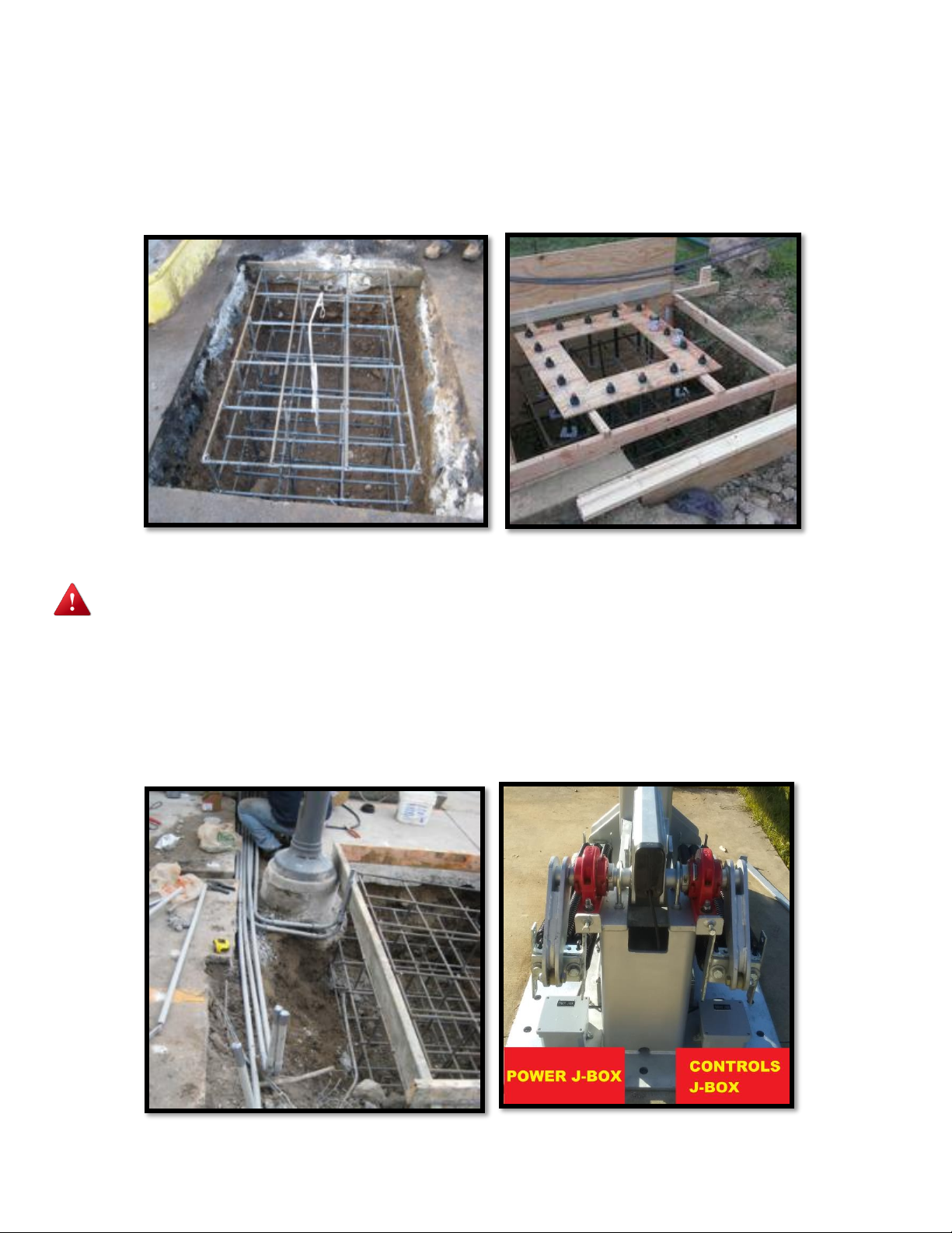
3. Servo Drive is located in BCP. The Motor and Encoder cables will be pulled from barrier
throughappropriateJ-Box(Orange=Power/Green=Control)thenintoBCP. Note:Ifdistanceisover
90 feet from BCP to Actuator contact RSSI for assistance.
4. If Actuator Heat Pad is supplied, the Heat Pad is powered through the BCP terminals 1H1 and
1H2 and wired to the Barrier Power J-box (splices). Ground wire will need to be pulled to J-Box as
well (check conduit legend for wire gauge needed). 3 Wires need.
5. The 24Vdc Traffic Lights are powered through the BCP PLC outputs and terminal blocks.
6. The 24Vdc Barrier Warning LED Lights are powered through the BCP PLC and wired through
the Control J-Box then terminated in J-Box. 2 wires needed
7. The IR Beams (if applicable) are powered through the BCP +24Vdc (Red wire)/-24Vdc (Black
wire) power terminal blocks to each IR Beam (splices in stands) Connect the Red wire to Brown
and Gray wires of IR pigtail and Black wire to Bluewire of IR pigtail.
8. The Barrier Heat Thermostat (mounted outside Panel) is connected at BCP terminals +24Vdc
and PLC input (splices at thermostat); if applicable.
Control Terminations
1. Servo DriveinBCP,anin-linebreakout board willneedtobeterminatedandpluggedintoServo
Drive in Panel.
2. BCP receives vehicle presence indications from the LOOPS in the roadway to the front of the
LOOP DETECTORS in the BCP. (Bottom DIP switch must be set to right position at this point).
3. BCP receives INPUTS from IR Sensor (if applicable) (black wire on sensor pigtails) the black
wire is connected to blue wire connected on PLC.
4. BCP controllerreceivesacontactclosurefromthethermostat(mountedoutside)totheBCP PLC
inputs. This activates the barrier heat grid system.
5. If BBU is provided, BCP receives INPUT from Battery Backup Panel (BBP) when commercial
power is lost and/or when a Low Voltage condition is present. BBP terminations are marked
(+24VDC) 13 and 14. The BCP terminations are mark (+24VDC), (I:1/0) for Loss of Power and
(I:1/1) for Low Voltage condition.

Installation Manual
March 3, 2022
Page 11 of 25
Installation of Servo Cables
●Install 1-1/4” Flex Conduit to the Power J-Box and 1” Flex Conduit to the Control J-Box.
Power and Control J-Boxes.
●Locate and Unroll Orange Power Cable and Green Encoder Cables at barrier. Protect
terminated end from damage then pull the unterminated end of cable through J-Boxes and to
Control Panel. Orange=Power J-Box, Green=Control J-Box. Connect terminated ends to
Actuator.
●Terminate 2 wires from BCP for Warning Lights in Control J-Box.
●If applicable, Terminate 3 wires from BCP for Heating Pad in Power J-Box.
●Once Servo Cables have been pulled through conduits to BCP, verify correct Drive location
for cables and make a service loop then cut off excess.

Installation Manual
March 3, 2022
Page 12 of 25
●Terminate Orange Cable to drive by stripping plastic sheathing from section of cable at end.
Placing exposed cable shielding under bonding plate then securing. Connect U/V/W wires
to harness plug then plug into bottom of Servo Drive.
●Terminate MRBK+ and MRBK–wires back to Terminal Block.
●TheGreenControlsCablewillterminateintoabreakoutboardthatwillplugintoServoDrive.
Remove 6”-8” of rubber sheathing on cable. Place cable on breakout board mark where to
cut cable shielding. Leave enough metal shielding to bond to plate at bottom of breakout
board. Use small ziptie to secure to bonding plate. Using wiring diagram, terminate each
wire. Don’t leave much excess, it can be difficult to close breakout board. Plug into front of
the Servo Drive then secure with two small screws. (pics on next page)

Installation Manual
March 3, 2022
Page 13 of 25
Wire Color
Breakout
Board
Terminal
Wire Color
Breakout
Board
Terminal
Black
1
White/Gray &
Orange
6
White/Black
2
Gray
7
Red
3
White/Green
10
White/Red
4
White/Orange
11
Green
5
Shield wire
0

Installation Manual
March 3, 2022
Page 14 of 25
Installation, Termination, and Testing of Fiber Cable
●Fiber converters are located in the BCP and in location near Operator Control Console.
●Fiber must be run in locations where the network communication distance exceeds 300 feet.
●A technician terminates the fiber and conducts a BASIC go/no go indication test. Based on
the performance of the fiberoptic link, if there are any issues, further testing with OTDR and
certification may be required.
●Connecting the fiber terminations (ST) to the fiber convertors
1. Line-up pegs with slots, push in and turn clockwise to lock
2. There is a (TX) transmit and (RX) receive (marked on convertor)
3. Take each pair of fiber cables (already terminated and tested) and connect to TX
and RX
4. Connect other end of fiber optic cable and termination to RX and TX (opposite)
5. You should get LINK light indication on fiber convertor, if not, reverse connectors
●Cleaning the fiber terminations before, during and after the termination procedures is a key
to success.
NOTE
It is highly recommended to use experienced technicians trained to
install, terminate, test, and certify fiber. After installing, at a
minimum test connection with an OTDR tester.
CAUTION
The Fiber cable is designed to be a straight run with no splices or
severe bends or stretching.

Installation Manual
March 3, 2022
Page 15 of 25
6 Attachments
1. Safety Loop Set-Up
2. Servo Drive Set-up
3. Vehicle Detector Loop Installation
4. Traffic Light Installation
5. Commissioning Checklist
* * END OF SECTION * *
RSSI Barriers LLC
6530 E Highway 22
Panama City, FL 32404
(850) 871-9300
www.rssi.com

Installation Manual
March 3, 2022
Page 16 of 25
ATTACHMENT1–SAFETY LOOP SET-UP
Safety Loop Set-up
1. Ensure 24v power supply is on.
2. Install the frequency plug with the wires from the safety loops. Loop detector should flash
red/green and then go to solid green indicator light.
NOTE
Ensure safety loops are clear before powering safety loop detectors.
Figure 1, Safety Loop Detector
3. Ensure the dipswitches are in the correct position; Factory settings are to the left, reset
bottom two dipswitches to the right (train to infinity and normally open).
4. Top two dipswitches are sensitivity settings. Factory settings are to the left (low sensitivity),
reset sensitivity to high (top two dipswitches to the right). Test safety loop sensitivity and
make adjustments as needed.
Figure 2, Side of Safety Loop Detector
NOTE
Sensitivity settings are Low, Medium Low, Medium High, High

Installation Manual
March 3, 2022
Page 17 of 25
ATTACHMENT3-SERVO DRIVE SET-UP
FROM THE MAINTENANCE TOUCH SCREEN IN THE BCP
Homing the Barrier
1. Turn on Servo Drive Fuse. On the maintenance touch screen in the BCP, go to the main
screen and check for any alarms and reset or clear.
2. At the Main Screen, go to the LOGIN box and login: “RSSI”password: “32404”.
3. Once you have logged in at the Main screen, select the HOME box and then at the
HOME menu press the red HOME button. The Home button will flash while homing,
once it has completed the process the green BARRIER HOMED button will appear. The
barrier is now homed, select Main to return to main screen. If the barrier continues to
HOME and shows no movement, press the ABORT HOME button then contact RSSI for
support.
WARNING
If the barrier is not in the CLOSED position it will start moving Down when HOMING
button is pressed.
Figure 9, Home Menu
Barrier Control
1. From the MAIN MENU, press the BARRIER CONTROL button (See Fig 10).
Figure 10, Main Menu

Installation Manual
March 3, 2022
Page 18 of 25
2. Inside the BARRIER CONTROL menu use the MOVE CLOSED/OPEN buttons to
operate the barrier a few cycles. In the OPEN(up) position to ensure the Locking Tab at
end of the beam clears the roadway and ensure the CLOSE(down) position is all the way
down and sitting firmly in the receiving buttress.
Barrier Control Menu
NOTE
If the Peak Current is higher than 20 Amp, it may indicate that the barrier
position needs to be adjusted.
3. JOG/TEACH screens: use JOG to position barrier–then TEACH open/closed lane
positions. Closed position should read around 3.5 and open position should read about
290 depending on roadway.

Installation Manual
March 3, 2022
Page 19 of 25
ATTACHMENT4-VEHICLE DETECTOR LOOP INSTALLATION
GUIDE
INTRODUCTION
This loop installation guide is intended to illustrate the steps involved in installing a "saw cut
type" vehicle detectorloop. Loop sizes shown in the figures and illustrations vary according
to the detection requirement being accommodated. The photographs are for typical loops
used in conjunction with traffic signals.
Figure 1 Figure 2 Figure 3
INSTALLATION INSTRUCTIONS:
1. Mark the loop outline on the pavement surface using either astring or rigid frame and aerosol
spray paintas shownin figures 1&2. Note that corners are diagonally cut to preventdamage
to wire insulation during placement of the wire in the slot (see figure3).
2. Placeamarkontheconcretesawbladetoinsurethesawcutdepthis2"deep. Thesawcutshould
be 1/4" wide at the lead cable slot and 1/8 inch wide for the loop slot.
3. Sawloopoutlinein pavement asshowninfigure4.
2
"
D
e
e
p
s
a
w
c
u
t
Figure 4 Figure 5
4. Clean debris from saw slot with compressed air, as shown in figure 5, and allow surface and
slot to completely dry.
5. After the loop size has been determined, refer to illustration 1 to determine the number of

Installation Manual
March 3, 2022
Page 20 of 25
turns of loop wire to be placed in the loop slot. It is important that the proper number of turns
are used.
6. Carefully install a continuous piece of the provided Loop Wire in the saw slot. Use Loop
Installation Roller to insure that the wires are in the bottom of the saw slot (see figure 7). Do
not use metal objects with pointed or sharp edges for this purpose!
NOTE
NO WIRE SPLICES ARE PERMITTED IN THE SAW SLOT!
Figure 6 Figure 7
7. Install backer rod in 4 inch segments in the saw slot as needed (see figure 6) to insure that the
wires are held tightly in the bottom of the slot.
8. Twist the two wires at least five turns per foot where they exit the saw slot.
Illustration 1
Other manuals for RSS-3000 Series
1
Table of contents
Popular Safety Equipment manuals by other brands

Power Hawk
Power Hawk P-16X instruction manual

SATA
SATA air vision 5000 operating instructions

Guardian Fall Protection
Guardian Fall Protection Cross Arm Strap instruction manual

Petzl
Petzl FREINO manual

Dräger
Dräger Oxy 3000/3000 MK II Trainer Instructions for use

Westfalia
Westfalia 29 13 69 Original instructions