SAFE FLIGHT SCc Angle of Attack User manual


Page 3 of 28 Sym A .
Dwg. 56201-2 .
PROPRIETARY NOTICE
This document contains proprietary information and covers
equipment in which Safe Flight has proprietary rights.
No data contained herein may be duplicated, used, or
disclosed, in whole or in part, for any purpose, without the
express written permission of Safe Flight Instrument
Corporation.
Safe Flight Instrument Corporation expressly reserves all
rights, including all rights of patent and copyright protection.
© SAFE FLIGHT INSTRUMENT CORPORATION
2016

Page 4 of 28 Sym B .
Dwg. 56201-2 .
TABLE OF CONTENTS
Para. Description Page
None Title Page......................................................................................................................1
None Revision Notice.............................................................................................................2
None Proprietary Notice .........................................................................................................3
None Table of Contents..........................................................................................................4
System Description.......................................................................................................51.01.1 SCc................................................................................................................................5
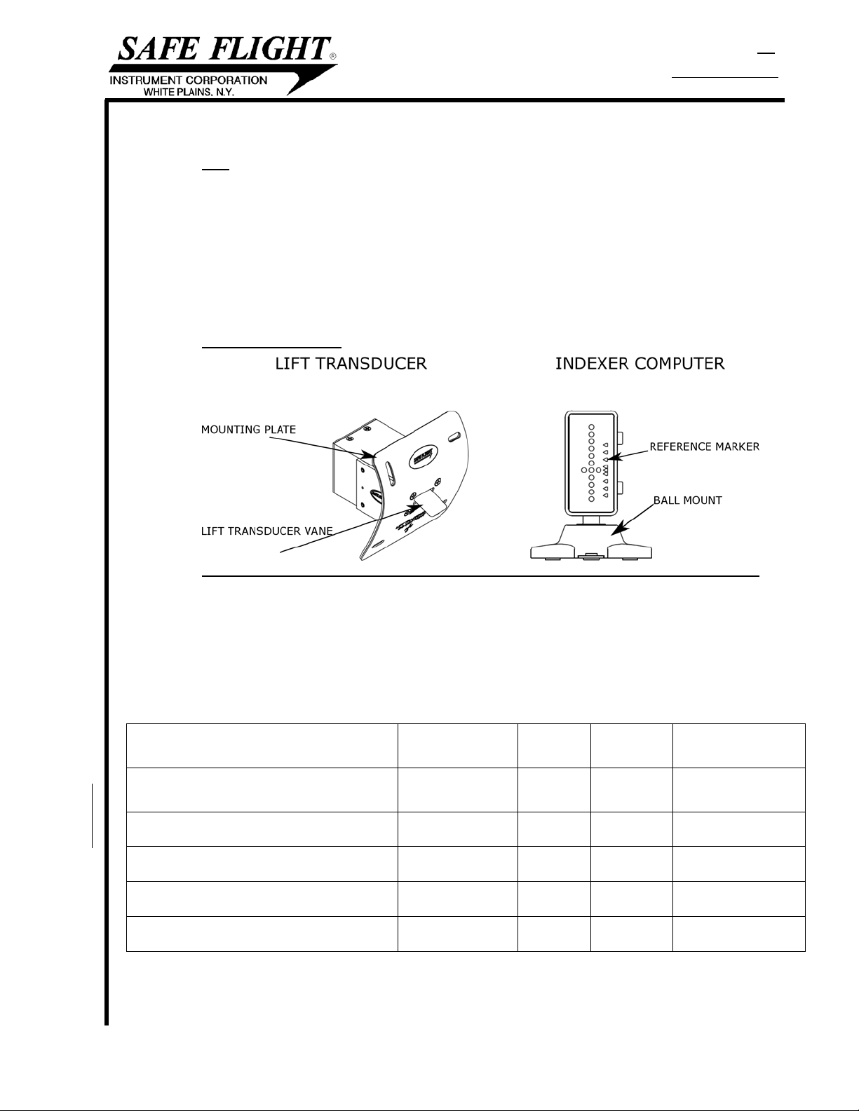
1.2 System Components.....................................................................................................5
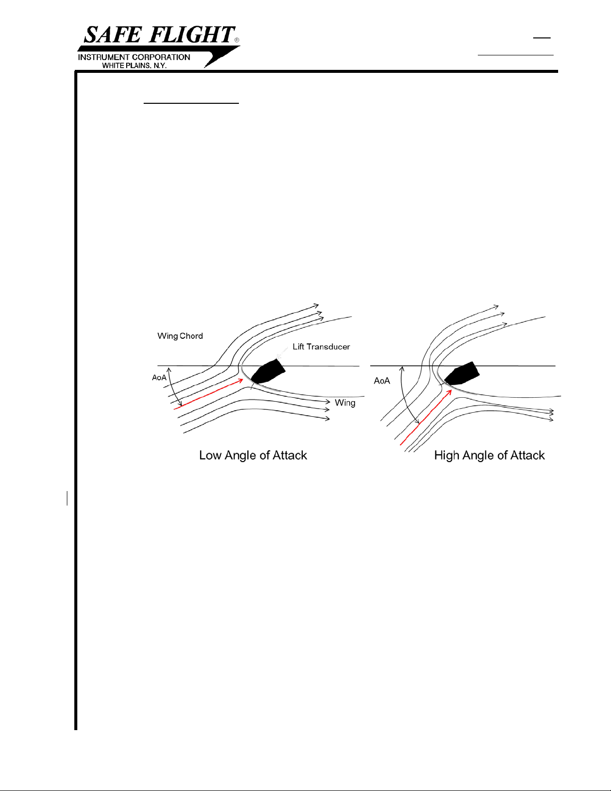
1.3 Theory of Operation......................................................................................................7
1.4 Scope............................................................................................................................8
1.5 Limitations.....................................................................................................................8
1.6 Specifications................................................................................................................8
Installation, Adjustment and Functional Check.............................................................92.02.1 Installation Procedure ...................................................................................................9
2.2Lift Transducer Wing Position.......................................................................................9
2.3 Doubler Installation .......................................................................................................9
2.4 Indexer Computer .......................................................................................................10
2.5 System Wiring.............................................................................................................13
2.6 Lift Transducer Installation..........................................................................................13
2.7 Ground Functional Test ..............................................................................................13
Flight Check and Adjustment......................................................................................143.03.1 Background.................................................................................................................14
3.2 Transducer Location Verification Flight.......................................................................14
3.3 In-Flight Final Calibration Adjustment.........................................................................15
3.4 Final Lift Transducer Installation.................................................................................16
3.5 Precautions .................................................................................................................16
3.6 Weight and Balance....................................................................................................16
Troubleshooting ..........................................................................................................164.04.1 System Removal.........................................................................................................16
4.2 Failure Modes .............................................................................................................17
4.3 Instructions for Continued Airworthiness ....................................................................17
User Manual................................................................................................................185.05.1 General .......................................................................................................................18
5.2 System Display ...........................................................................................................18
5.3 Pre-Flight Ground Check Procedure...........................................................................18
5.4 Additional Button Press Functions..............................................................................19
5.5 Takeoff and Climb.......................................................................................................20
5.6 Cruise..........................................................................................................................20
5.7 Landing Approach.......................................................................................................22
5.8 Low Airspeed Awareness (LAA) .................................................................................23

Page 4a of 28 Sym .
Dwg. 56201-2 .
TABLE OF CONTENTS (continued)
Para. Description Page
None Appendices .................................................................................................................24
Appendix A:Method to Determine Lift Transducer Placement
Appendix B: Flight Check Data
Appendix C: Lift Transducer Adjustment Based on Indication

Page 5 of 28 Sym B .
Dwg. 56201-2 .
SYSTEM DESCRIPTION1.0
SCc1.1
The Safe Flight SCc Angle of Attack (AoA) System is an accurate wing lift measuring and
display system designed as an aid to help the pilot achieve consistent takeoff, climb, cruise
and landing approach performance. Using a wing leading edge flow measurement device,
the SCc AoA System precisely senses the flow field about the wing’s leading edge. The SCc
AoA indication is accurate regardless of aircraft weight, wing loading, turbulence or wing flap
configuration. This system provides the pilot with AoA-based guidance for high-lift operational
conditions including normal and short-field takeoff, Best Rate (Vy) and Best Angle (Vx) of
climb, wind-compensated Long Range Cruise (LRC), maximum endurance, normal and
short-field runway performance, and Low Airspeed (high AoA) Awareness (LAA).
System Components1.2
Lift Transducer Indexer Computer
The SCc AoA System consists of a wing leading edge mounted Lift Transducer and a
glareshield mounted Indexer Computer.
The installation parts are listed in Table 2. Table 3 lists standard hardware suggested for the
installation.
Table 1: SCc Included Components
COMPONENT PART NUMBER
WEIGHT
(lbs.)
VDC AMP
Installation Instructions and User Manual 56201-2_B
Quick Reference Guide
56202-2_A
Wiring Schematic Textron SC-C
70308800-15_A
Lift Transducer
C-14007-1
0.3
Indexer Computer
C-14061-1
0.2
10-32 V
0.20A @ 28V

Page 6 of 28 Sym A .
Dwg. 56201-2 .
Table 2: Installation Parts
Description
Hardware
Part Number
Quantity
Doubler
Lift Transducer Doubler
Plate
3704-223-1 1
Label Advisory Placard 55562-1 1
Backup Disc Assembly 1504-114-4 1
Ball Assembly 1504-128-4 1
Base & Spring Assembly 1504-126-4 1
Cover 1504-229-4 1
Cable Assembly, CAT5e 8 ft. length male to male 3704-150-2 1
Cable Assembly, CAT5e, Extension 8 ft. length male to female 3704-160-1 1
Table 3: Standard Hardware Needed
Description Part Number
Quantity
Needed
Flat Head 100 deg 6-32x1/2 MS34693-C28 3
Pan Head 6-32x1/2 MS51957-30 5
Nut, blind rivet NAS1329A06-75 4
For all standard hardware, equivalent components may be used. See AC 43-13 for guidance on the use
of equivalent parts. Any substitution is the sole responsibility of the installer.
Listed below are the tools needed to complete the SCc installation.
•Proper sheet metal cutting equipment
•Fine tipped pen
•Drill and drill bits
•Rivet nut installation tools
•Phillips head screwdriver
•Combination square with level
•(2) Plumb lines

Page 7 of 28 Sym B .
Dwg. 56201-2 .
Theory of Operation1.3
As the aircraft wing moves through the air it divides the air mass. At the center of this divided
airflow is a narrow region known as the stagnation point. The location of the stagnation point
uniquely represents the wing’s AoA.
As the AoA increases, the leading edge stagnation point moves aft chordwise on the lower
surface of the wing. The Lift Transducer senses the location of the stagnation point by means
of a spring-loaded vane. The Lift Transducer is designed to detect the location of the
stagnation point and relays this signal to the Indexer Computer.
The location of the Transducer on the wing is carefully chosen so that the sensed airflow is
optimized for all of the high lift performance regimes of the aircraft. These include near
maximum wing lift during normal and short-field takeoff and landing operations and the AoA’s
associated with optimized long range cruise and maximum endurance.
Decreasing the AoA of the wing moves the stagnation point forward (UP); increasing AoA
moves it aft (DOWN) as shown below. At a maximum aft position, wing lift rapidly decreases,
which is the AoA at which the stall occurs.
In the Aircraft Flight Manual (AFM) or Pilot Operating Handbook (POH), the speed at which
the stall occurs is given in terms of indicated airspeed. The stall speed varies with aircraft
gross weight, center of gravity, bank angle, maneuvering load and wing flap configuration. As
each of these is reflected by the movement of the stagnation point, the Lift Transducer
senses the wing’s leading edge flow field giving an accurate and repeatable indication of the
AoA.
The AoA, measured relative to stall, is displayed on the color-coded LEDs (green/amber/red)
on the Indexer Computer, which is mounted vertically on the instrument panel glare shield. A
pilot-selected reference mark may be set for the desired operational reference.
For Low Airspeed Awareness (LAA), high-AoA trend information supplements the aircraft’s
stall warning system by the display of two blinking red LEDs and a ‘Geiger counter’-like audio
output to the cockpit speaker and/or pilot headset. The audio begins when two amber LEDs
are illuminated and increases frequency as the AoA approaches stall.

Page 8 of 28 Sym A .
Dwg. 56201-2 .
Scope1.4
The system meets the requirements of FAA Memo AIR100-14-110-PM01, dated February 5,
2014, regarding the Approval of Non-Required Angle-of-Attack (AoA) Indicator Systems.
These installation instructions become the approved data necessary for the installation of the
SCc.
1.4.1 These installation instructions are FAA Approved Data to be utilized only for the installation of
the AoA system described herein on aircraft certified under 14 CFR Part 23 (or
predecessors). Provided all of the requirements of section 2.0 of this document are met, no
further FAA approval is required for the installation of this AoA system on a Part 23 aircraft.
If the limitations of section 2.0 are not met, further FAA approval may be required.
1.4.2 These installation instructions are only approved for the aircraft models listed: Cessna 172,
182 and 206.
Limitations1.5
1.5.1 The Safe Flight SCc System is non-required and is to be used only as advisory information to
the pilot. The system cannot replace the certified stall warning system. No performance credit
can be taken from the system, such as reduced approach speeds, reduced takeoff or landing
distances, etc.
1.5.2 The aircraft Pilot Operating Handbook or Aircraft Flight Manual always supersedes this
system’s manual.
1.5.3 SCc cannot be installed in a Commuter or Transport category airplane.
Specifications1.6
Operational Temperature Range
-45°C to 70°C (DO160G Level B2)
Survival Temperature Range
-55°C to 70°C (DO160G Level B2)
Operating Humidity Range
DO160G Level B (95% max.)
Operating Altitude Range
0 – 25,000 ft. (DO160G Level B2)
Operating Airspeed Range
VS0 to ~2 x VS0
Precipitation
No limitations
Icing
Not for use in icing conditions
Deicing Fluids
No limitations
Emissions of RF Energy
DO/160G Category M
Voltage Operating Range
10-32 V

Page 9 of 28 Sym .
Dwg. 56201-2 .
INSTALLATION, ADJUSTMENT AND FUNCTIONAL CHECK2.0
Installation Procedure2.1
The installation of the SCc AoA System requires installing the Lift Transducer on the leading
edge of the wing, installing the Indexer Computer, and system wiring. After installation, both
a ground functional and a flight check are performed. The data from the flight check is to be
recorded in Appendix B. If needed, Appendix C provides a guide for adjustment of the Lift
Transducer mounting plate on the wing to adjust the results obtained from the flight test data.
Lift Transducer Wing Position2.2
The following is a procedure for finding the initial location for the mounting of the Lift
Transducer.
The installation of the SCc Lift Transducer should typically be made on the wing opposite to
the existing stall warning device, at the same or close to the same spanwise position. This
location may be varied in order to facilitate the ease of installation access of the wing
components through an existing wing panel access.
The SCc System cannot be used as a replacement for or
modification of an existing FAA approved Stall Warning System.
NOTE
The location should be clear of any internal interference from ribs and other aircraft structure.
Be sure to note locations of pitot lines, wiring, fuel tanks, fuel lines, and other aircraft
hardware to avoid any interference.
The Lift Transducer is to be mounted initially at 1% chord. Use the method described in
Appendix A to determine the proper location for mounting the Lift Transducer. Place a mark
on the wing at this location. This will be the center of the cutout for the Lift Transducer
Doubler.
Doubler Installation2.3
Using the Doubler provided as a template, contour and temporarily tape the Doubler to the
leading edge of the wing. Align the center of the cutout of the Doubler with the leading edge
1% chord mark. Using a fine-tipped marker, trace the outline of the Doubler cutout so as to
mark the area of aircraft skin that is to be removed from the wing’s leading edge for the
installation of the Lift Transducer.
Remove the Doubler and reserve it for installation inside the wing.
Cut through the wing, as outlined by the Doubler cutout, to create the Lift Transducer
mounting hole.
Through a nearby access panel, insert the Doubler into the wing and align it with the leading
edge wing hole. Bend the Doubler to match the wing contour at this position. Rivet the
Doubler to the inside wing surface using appropriate rivets, in accordance with AC 43-13.
Ensure that sufficient space is left for rivnut installation.
Place the Lift Transducer in the hole, forming the Mounting Plate to the contour of the leading
edge. As with the Doubler, the Lift Transducer Mounting Plate has been contoured to the
approximate curvature of the wing’s leading edge. Final adjustments to the Lift Transducer
mounting plate will be made during the installation on the wing.

Page 10 of 28 Sym .
Dwg. 56201-2 .
Make a mark on the wing corresponding to the center point of the vertically slotted holes in
the Lift Transducer mounting plate.
At these marks, drill two pilot holes through the wing and through the Doubler. When the Lift
Transducer is installed, it should be able to be moved 0.25’’ forward (up) and aft (down).
These holes will be used to initially mount the Lift Transducer for flight test. If the range of
travel of the Lift Transducer is correct, enlarge the pilot holes and install two rivet nuts or
equivalent.
Indexer Computer2.4
The Indexer Computer is installed on top of the instrument panel glareshield.
First, select a position for the Indexer Computer on the instrument panel glareshield, ensuring
the best viewing angle for the pilot. The Indexer Computer should NOT interfere with the
pilot’s view of the primary flight instruments or view outside of the aircraft or cause
distraction.
The Backup Disc Assembly is then installed. This disc is mounted under the glareshield,
screwed directly to the glareshield and provides support for the Ball Mount Assembly and
Indexer Computer.
Next, mark the center hole location for the backup plate. Using the Base Assembly as a
template, mark the centers of all three outer holes. Open center hole to accept MS51957-30
screw. Open the outer holes to accept MS24693-C28 screws.
Screw the Backup Disc Assembly to the glareshield using the MS51957-30 screws or
equivalent, reaching through instrument panel to mount Backup Disc Assembly in the
determined location as shown below.
The instrument panel may need to be removed for the
installation of the Backup Disk Assembly.
NOTE
Backup Disc Installation

Page 11 of 28 Sym .
Dwg. 56201-2 .
Next, the Base Assembly is mounted to the Backup Disc Assembly. Using MS24693-C28
screws or equivalent, attach the Base Assembly to Backup Disc through glareshield as
shown above.
Ball Assembly Installation to Indexer Computer
Install the Ball Assembly through the Cover into the Indexer Computer. Rotate the screw in
the Ball Assembly until the ball is captured securely by the threaded insert on Indexer
Computer. The stem on top of Ball Assembly should fit snugly into opening on Indexer
Computer. When mounted, the buttons will appear on the right-hand side of the Indexer
Computer with the High AoA side of the display on top.
Base Assembly Installation to Backup Disc

Page 12 of 28 Sym .
Dwg. 56201-2 .
Insert the Ball Assembly into the Base Assembly. Rotate the Indexer Computer until view of
front face is acceptable.
Lock the cover onto the Base Assembly. Locking the cover exercises the locking rings on the
Base Assembly, requiring greater force to move the Indexer Computer.
Placard system “AoA not for use as a primary flight instrument” using the label supplied or
equivalent.
Connect the Cable Assembly, CAT5E Extension 3704-160-1 and the Indexer Power Harness
to the Indexer Computer.
Ball Assembly Installation to Base Assembly

Page 13 of 28 Sym B .
Dwg. 56201-2 .
System Wiring2.5
When ringing out wires in TYCO 1-794617-2 or equivalent connector,
DO NOT insert oversized pins or probe into the main connector.
WARNING
Wire the system in accordance with the Wiring Schematic 70308800-15 Rev. A. Maximum
current in any wire is 0.5 A. All items marked as reference (REF) are to be customer
supplied.
Power for the SCc is supplied through the aircraft power bus. The system is also tied to the
navigation lights, to facilitate day/night dimming. See the Wiring Schematic for details.
Ensure 1.9” minimum bend radius for either CAT5e cable
assembly Do not overcompress either CAT5e cable via
clamping.
NOTE
3704-160-1 should be inserted into Indexer Computer. 3704-150-2 should connect to the
Lift Transducer.
FAA approval of this document includes authorization for
connection of audio output into aircraft audio system. See
Wiring Schematic for details on audio specifications.
NOTE
Lift Transducer Installation2.6
Connect the Lift Transducer to the Cable Assembly, CAT5E, 3704-150-2.
Mount the Lift Transducer using two screws in the vertical slotted holes on the mounting
plate.
Ground Functional Test2.7
The Lift Transducer vane should move freely in both directions with no resistance.
With the electrical power OFF the Indexer Computer should not be lit.
Turn the main power ON. The Indexer Computer will perform a Power-on Self-Test,
illuminating all of the LEDs for approximately five seconds. The audio alert will also be active
during the self-test. After the self-test, the audio will cancel and the LEDs will indicate the
current position of the transducer.
The single red LED will continue to blink at 1 Hz until the system
has been calibrated in flight.
NOTE
Observe the Indexer Computer for a transition to the low-AoA side of the display, with a
single green LED illuminated when the Lift Transducer vane is gently pushed down (AFT).
Gently push the vane up (FORWARD). The Indexer Computer should transition to the high-
AoA side of the display, followed by the flashing of the two red LEDs, indicating LAA.
Turn the navigation light switch on and observe Indexer Computer display dims.
The aircraft’s stall warning system is the primary stall warning. The
AoA System is non-required equipment and is to be used only as
supplemental information to the pilot.
CAUTION

Page 14 of 28 Sym B .
Dwg. 56201-2 .
FLIGHT CHECK AND ADJUSTMENT3.0
This procedure may involve flight at near stall conditions. Choose a safe
altitude to enable recovery in the event of a stall. The best results are
found in non-turbulent conditio
ns.
CAUTION
The aircraft’s primary stall warning system calibration must be
verified prior to AoA System calibration.
NOTE
Background3.1
The Safe Flight SCc System is calibrated using a two-step process: accurate placement of
the Lift Transducer, followed by an in-flight calibration procedure using Landing Approach
and Low Airspeed Awareness data points.
Once the Lift Transducer is installed in the correct location, the system is ready for in-flight
calibration.
Transducer Location Verification Flight3.2
Using the POH recommended landing approach speed, power setting, and flap extension, fly
a simulated approach (at a safe altitude for possible stall recovery) with the Lift Transducer
installed at its initial location.
If the Indexer Computer displays any of the following indications, the system is ready for the
final in-flight calibration.
Acceptable Indications before In-Flight Calibration
If not, the Lift Transducer needs to be moved on the wing. Land and follow Appendix C for
guidance on how to adjust the Lift Transducer. Then, repeat the verification flight test
procedure.

Page 15 of 28 Sym B .
Dwg. 56201-2 .
In-Flight Final Calibration Adjustment3.3
Once the lift transducer has passed the transducer location verification flight, the system is
ready for in-flight calibration.
At a safe altitude for possible stall recovery, using the POH recommended landing approach
speed, power setting, and flap extension, fly a simulated approach. Simultaneously, press
and hold both the top and bottom buttons for two seconds to enter the calibration mode. All of
the red, amber, and green indicators will begin flashing.
Press the bottom button to select the Landing Approach calibration
mode. Continue flying the aircraft at the normal approach airspeed and
descent rate. The Indexer Computer will begin flashing slowly the green
center ON-SPEED indication for five seconds.
Continue flying the aircraft at the normal approach airspeed and descent
rate. The Indexer Computer will begin flashing quickly the green ON-
SPEED indication while the system is recording data for five seconds.
If the calibration is successful, the green ON-SPEED indication will
change to solid (non-flashing).
If the calibration is unsuccessful, the Indexer Computer will return to
flashing slowly the ON-SPEED indications for 5 seconds, and then will
transition again to flashing quickly for another 5 seconds. This sequence
will repeat until the calibration is successful.
When the approach setting has been successfully accomplished, without
adjusting power, pitch the aircraft nose up, slowing the aircraft to the
speed where aircraft stall warning just begins to sound. Hold this speed.
Press the top button to transition to the LAA calibration mode. The two
red lights will begin slowly flashing for five seconds.
The two red lights will begin quickly flashing for another five seconds.
During this time, maintain the stall warning target speed (at a constant
power setting).
If the calibration is successful, the red LAA indication will change to solid
(non-flashing).
Indication for Calibration Mode
(all LEDs flashing)
Indication for LAA
Calibration
(Red LEDs Flashing)
Indication for
ON-SPEED
Calibration
(Center Green LEDs
Flashing)

Page 16 of 28 Sym B .
Dwg. 56201-2 .
3.3 In-Flight Final Calibration Adjustment (continued)
If the calibration is unsuccessful, the system will return to flashing slowly for 5
seconds; then will transition again to flashing quickly for another 5 seconds.
This sequence will repeat until the calibration is successful.
Press and hold both the top and bottom button for two seconds to exit the calibration mode.
After a successful calibration, at a safe altitude, fly a simulated
approach using the POH recommended landing approach
speed, power, and flap extension. Verify that the given On-
speed (five dots) is lit within +/–5 knots of the POH referenced
speed. Without adjusting power, pitch aircraft nose up, slowing
the aircraft so that the Indexer Computer displays two amber
LEDs. Verify LAA audio is active and stall warning is not.
If verification fails, repeat section 3.3.
NOTE
Pressing and holding both top and bottom buttons
simultaneously for two seconds at any time exits the calibration
NOTE
Final Lift Transducer Installation3.4
Once the location of the Lift Transducer has been determined and the system has been
calibrated, mark the center of the horizontal slots on the Lift Transducer mounting plate.
Disconnect the wiring and remove the Lift Transducer from the wing.
Install rivet nuts or equivalent in the horizontal slot center locations previously marked.
Reconnect and reinstall the Lift Transducer, using all 4 screws.
Precautions3.5
DO NOT paint or otherwise coat the vane of the Lift Transducer. All parts are adequately
protected against corrosion. Any additional coating will interfere with proper operation.
DO NOT attempt to bend the Lift Transducer vane to obtain any adjustment. Refer to Section
3.0 of these instructions for the proper method of adjusting the Lift Transducer.
Weight and Balance3.6
The Aircraft Weight and Balance and Equipment List for the aircraft should be updated to
include the installation of the SCc components listed in Tables 1, 2, and 3.
TROUBLESHOOTING4.0
System Removal4.1
To disconnect the Indexer Computer from the Base Assembly, insert a flat-head screwdriver
into the slot at the end of each leg. Lift up to release. Rotate the cover to access the screw
heads. Pull gently on the Indexer Computer to remove the system after the cover has been
lifted.
Remove Lift Transducer by unscrewing from rivnuts on wing. Cover the location with a cover
plate if necessary.

Page 17 of 28 Sym B .
Dwg. 56201-2 .
Failure Modes4.2
The Indexer Computer and Lift Transducer are not field repairable. If the operation of the
system is in doubt, apply power to the system. If the system successfully completes the
Power-On Self-Test, then the system is in operation and can be flight checked.
If the Power-On Self-Test is unsuccessful, hold buttons A and B for two seconds while power
is still supplied. The display will illuminate all reference marker segments and then will
illuminate a particular segment of the Indexer Computer display. Make note of these
illuminated segments, as this will aid in diagnosing the problem.
Visit www.safeflight.com for additional troubleshooting actions.
When using the website troubleshooting guide, have the following information on hand:
1. Unit Part Number
2. Unit Serial Number
3. Unit Software Revision
4. Fault Code (which LEDs are illuminated
on the Indexer)
Label on Indexer Computer
(Typical)
The Part Number, Serial Number, and Software Revision can be found on the nameplate on
the lower surface of the Indexer Computer.
Instructions for Continued Airworthiness4.3
Perform the functional ground check in accordance with paragraph 2.7 at each annual
inspection or anytime the SCc Indexer Computer or Lift Transducer has been disconnected.
Following the Power-On self test, the single red LED will
continue to blink at 1 Hz until the system has been calibrated in
flight.
NOTE
If the Lift Transducer has been replaced or if the calibration of the system is in doubt, perform
the calibration procedure in accordance with paragraph 3.3.
The “Transducer Location Verification Flight” procedure of
paragraph 3.2 is only to be performed for the first transducer
installation. When paragraph 3.2 has been completed no
further transducer location adjustments can be performed.
NOTE

Page 18 of 28 Sym B .
Dwg. 56201-2 .
USER MANUAL5.0
General5.1
The Safe Flight SCc AoA System, when properly installed and calibrated in accordance with
the installation instructions, will serve as a reliable aid for flight associated with normal and
short-field takeoff, climb, long range cruise, maximum endurance, and normal and short-field
landing approach.
The following indications listed in the User Manual for each
desired flight profile are listed as examples only. The indication
for each of these scenarios may differ from aircraft to aircraft.
Consult the POH/AFM for proper speeds of all maneuvers.
NOTE
This system is designed to be used in an advisory manner only.
For proper procedures in flight, consult the POH/AFM
.
NOTE
The SCc System is accurate in the on speed calibrated region,
±5 knots for the Landing Approach indica
tion.
NOTE
System Display5.2
System Display
Pre-Flight Ground Check Procedure5.3
With the electrical power OFF, the Indexer Computer should not be illuminated.
With the electrical power ON, the Indexer will illuminate and perform a self-test. All of the
LEDs will illuminate for approximately five seconds. The audio warning will also sound for the
duration of the system test.
If a system calibration is required, the red LED on the top side of the display will blink slowly
to signal that calibration is required. Do not use the SCc until a system calibration is
completed. Refer to Section 3.0 for calibration procedure.
If any indication is not achieved as specified, discontinue use of the SCc System until a
detailed check can be made to determine the cause.

Page 19 of 28 Sym B .
Dwg. 56201-2 .
*This function is only available with S/N 167304-01 and above and software version 1.3.0 marked on the
Indexer nameplate.
Additional Button Press Functions5.4
5.4.1 Reference Marker
5.4.1.1 Overview
The Reference Marker, a scrolling white LED arrow on the right-hand side of the Indexer
Computer, is used to designate a pilot-selected AoA reference. The flight modes described
below show the typical location to place the Reference Marker for the desired flight condition.
5.4.1.2 Moving the Reference Marker
The two buttons on the side of the Indexer Computer control the movement of the Reference
Marker. A quick press of the top button moves the marker closer to the High AoA side (UP), a
quick press of the bottom button moves the marker towards the Low AoA side (DOWN) of the
display.
5.4.2 Audio Mute*
5.4.2.1 Normal operation is with the LAA audio active (unmuted). To mute the LAA audio, press and
hold the top button for 4 seconds. After 4 seconds, you will hear a beep. This beep confirms
that the audio is now muted.
5.4.2.2 To unmute the audio, press and hold the top button for 4 seconds. After 4 seconds, you will
hear two beeps. Two beeps confirms that the audio is now unmuted.
When the Indexer Computer displays the AoA shown below, the audio will automatically
unmute. This will also be confirmed with two beeps.
Angle of Attack for Automatic Unmuting
5.4.2.3 When the Indexer Computer is powered off and then back on, the LAA audio will
automatically unmute.
5.4.3 Brightness Control*
The brightness can be adjusted through the use of the bottom button on the side of the
Indexer Computer. Holding the bottom button for two seconds will toggle between day/night
dimming. This button can be used to override the dim setting selected through the navigation
light switch.
Table of contents