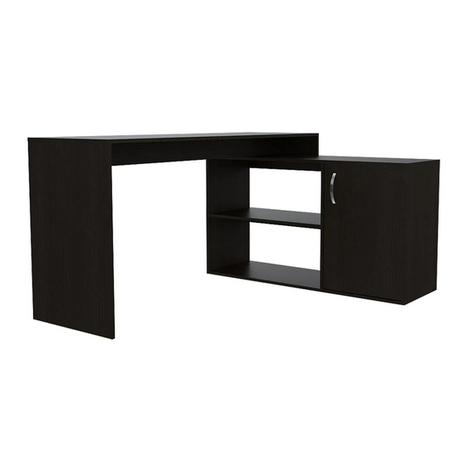
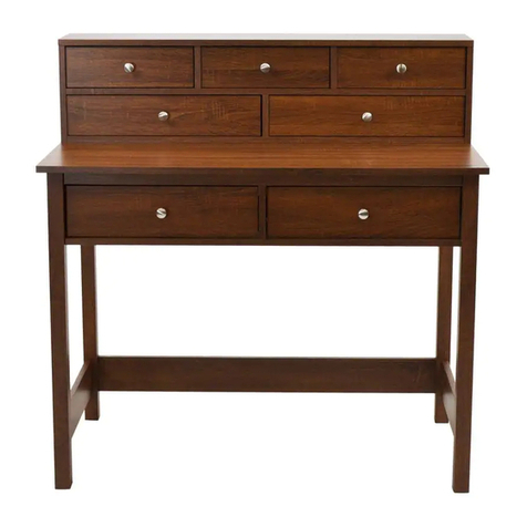
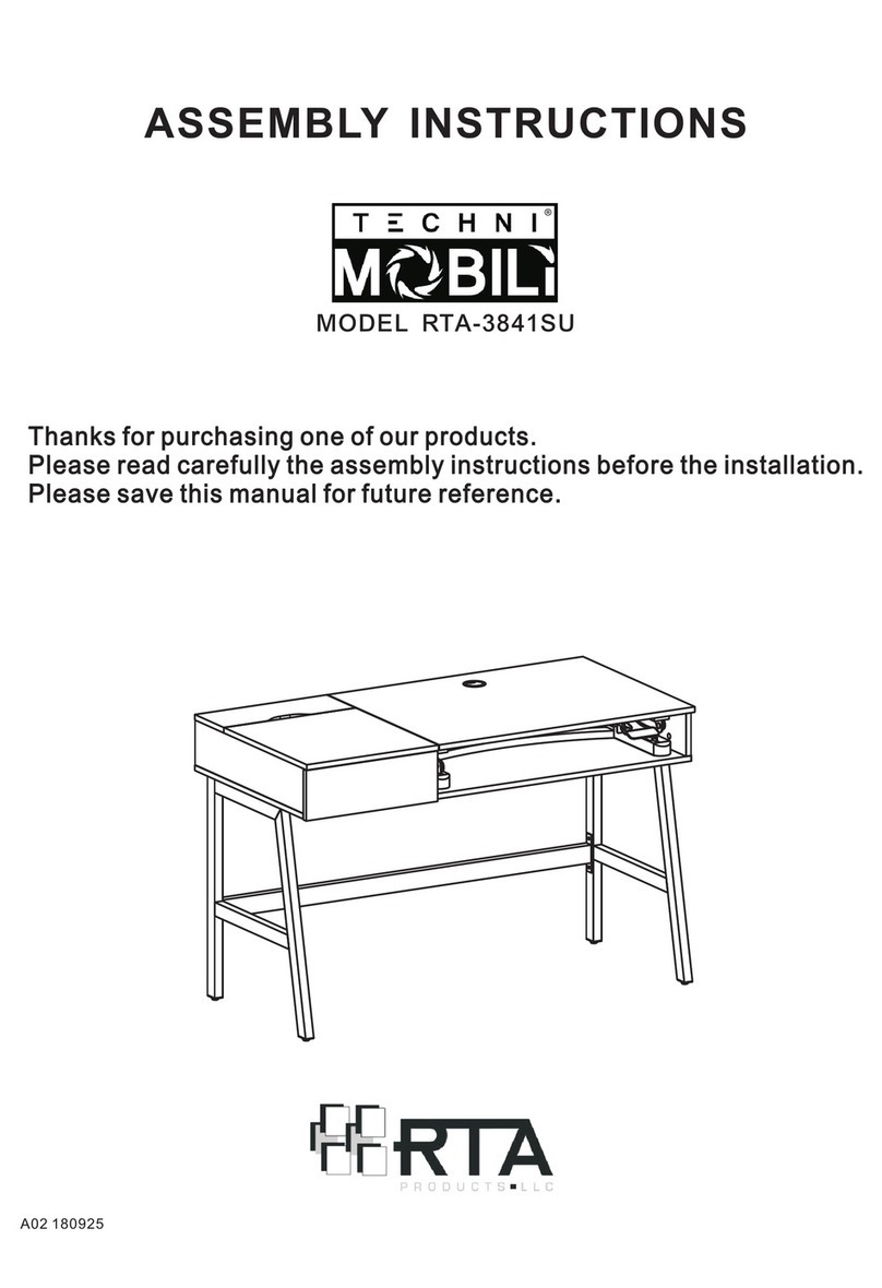
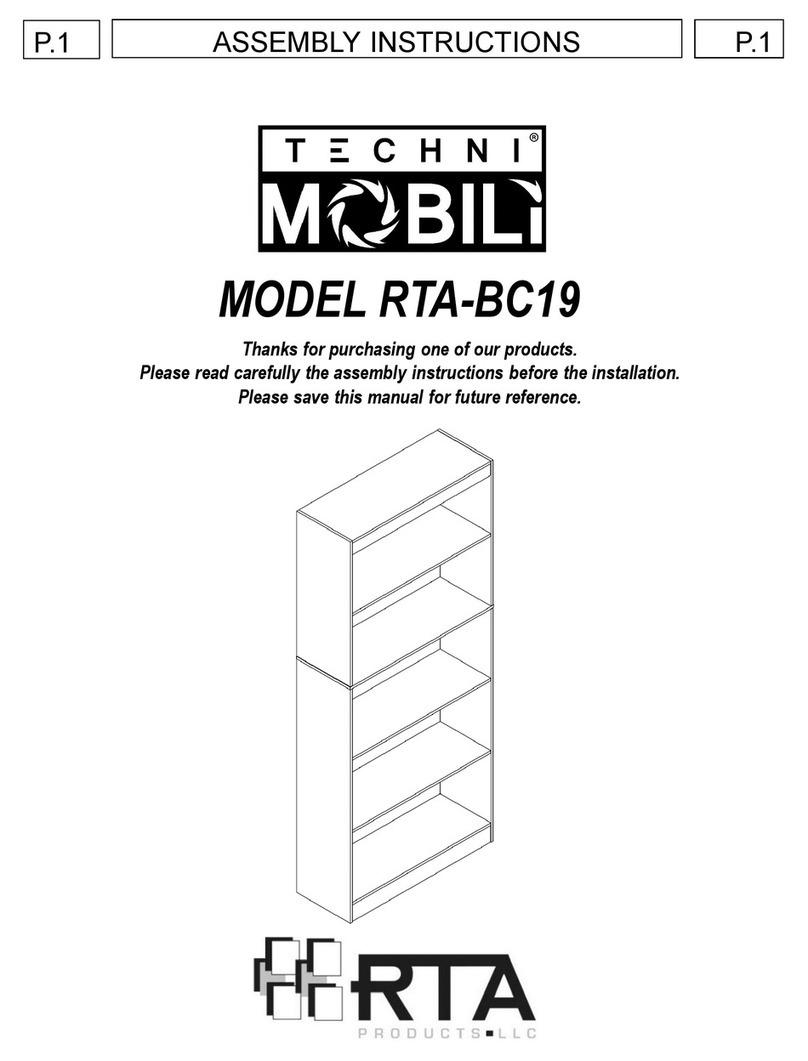
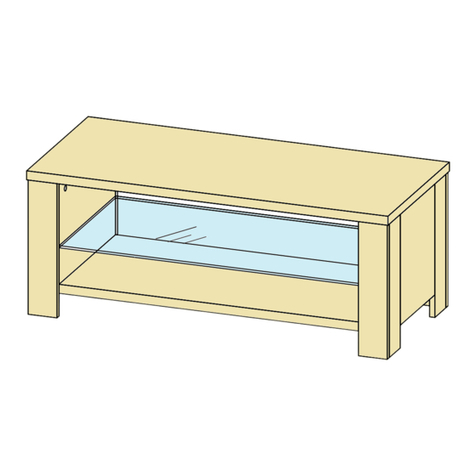
RTA Techni Mobili RTA-1459 User manual

MODEL RTA-1459
ASSEMBLY INSTRUCTIONS
Thank you for purchasing our product
REV.052021-1

•Please read carefully the assembly instructions
before the installation.
P.1 RTA-1459 P.1
•Do not discard this manual or any of the packaging
material until the unit has been completely assembled.
•Might require two people.

12
x1
P.2 RTA-1459 P.2
1
x2 2
x1
Back leg
(main) 4
x1
3
x1
Front-Left leg
(main) Front-Right leg
(main) Left Panel
(main external)
MAIN PARTS LIST
5
x1 Right panel
(main external)
10
x1
Back external
panel (exp. tbl.) 13
x1 14
x1
Right external
panel (exp. tbl.) Left internal
panel(exp. tbl.)
Expandable tabletop
24
x2 Sliders for
drawer
23
x2 Sliders for
expandable
table
22
x1 Drawer
bottom
panel
20
x1 21
x1
Drawer back
panel Drawer right
panel
15
x1 16
x1
Right internal
panel (exp. tbl.) Left connecting
panel (exp.)
6
x1
Back panel
(main external)
7
x1 Main tabletop
19
x1 Drawer left
panel
Drawer front
panel
18
x1
17
x1 Right connecting
panel (exp.)
8
x1 Front-Left leg
with wheel
(exp. tbl.)
9
x1 Front-Right
leg with
wheel (exp. tbl.)
11
x1 Left external
panel (exp. tbl.)

P.3 RTA-1459 P.3
MAIN PARTS LAYOUT (FOR REFERENCE):
MAIN TABLE
EXPANDABLE TABLE
DRAWER
❷
❸
LIST OF SCREWS AND FITTINGS
PART
QTY ITEM
A22 Wooden dowel
B40 Cam bolt M6x40
C40 Cam lock Ø14mm
D24 ST4x12
E12 ST4x40
F12 ST4x14
Allen wrench
7
10
5
1
4
11
17
16
15 9
8
20 21
1
22
19 18

P.4 RTA-1459 P.4
☛This unit uses cam bolts and locks. The following explains how to use them.
This is not an assembly step; it is a guide for when you are actually doing the
assembly using this kind of hardware.
Cam Bolt Cam Lock
1. Screw the bolt into the
corresponding panel.
2. Place the other panel over the
panel with the bolt, then insert the
cam lock to join the bolt’s head.
If the cam lock does not want to
enter, check its proper alignment.
There might be a very small gap
between the panels which is normal.
3. Turn the cam lock clockwise. This
will lock the parts together and will
close any gaps.
Alignment: The cross
points towards the panel
with the bolt.

P.5 RTA-1459 P.5
BEFORE YOU START THE ASSEMBLY, PLEASE READ THE FOLLOWING TIPS AND WARNINGS.
❶Do a quick inventoryto
make sure the package
contains all the parts and
hardwarelisted in the
assembly instructions.
❷Missing, damagedand
defective parts can be
replacedat no cost to you.
Please refer to the CONTACT
card includedwith the
product.
❸The replacementparts service is
limitedto the continentalUnited
States. If you reside in Alaska,
Hawaii, Puerto Rico,
U.S. Dependenciesor other
countries, please contact the supplier
from where the unit was purchased.
❹If during assembly you
find an issue or need
clarification, pleasecontact
our Customer Service for
assistance.Please referto the
CONTACT card includedwith
the product.
❺On each step read the
instructions andanalyze the
illustrationsthoroughly
before proceeding to do the
assembly.
❽Do not overtighten
or force the screws as
they might break, strip,
damagethe threadsof
the holes or get stuck
inside the part.
❻Make sure you understand
which hardwarewill be used
on each step. Using the wrong
size of screw, bolt or pin might
strip the threads or cause
damage to the part in which it
is beingused.
❼To avoid misalignments,
always leave the screws
loose and tighten them until
all pieces are positioned
correctly.
❾Sometimes the laminate might cover partially or entirely
the hole on a panel.If there is no visible hole for the screw,
pass and press the tip of your finger over the areawhere
the hole shouldbe located to feel the indentation,and once
found, carefully pierce the laminateto reveal the hole
underneath.
❿If the hole seems too small for the screw, first make
sure you are using the correct size of screw and that it’s
been installedin the correct hole.If the hole still appears to
be toosmall, carefullypierce the laminateto revealthe
hole’s actual size.

ASSEMBLY STEPS 1 THROUGH 9: TO ASSEMBLE THE MAIN TABLE
P.6 RTA-1459 P.6
Place the Slider 23A on the panel 4and fix it with the screw Das shown.
STEP 2
Hardware/Tools:
DST4x12 3
Pcs
1. Grab the slider in your hand and open it in the exact direction shown below,
where the smaller piece will be part “B”.
2. Press the lever for part “B”, in the direction indicated, while pulling part “B” away
from part “A”.
3. After separated, set aside the smaller pieces 23B as they won’t be used until
later on step 10.
STEP 1
23
23A 23B
23A 23B
All the sliders 23 must be separated into 2 pieces:
23A: These will be double pieces with the ball bearings.
23B: These are single pieces.
To separate them, follow the instructions below:
AB
4
23A
(Front)
Scan QR Code to view
this step
Pay attention to the holes you must use
(Front) 23A

P.7 RTA-1459 P.7
Place the Slider 23A on the panel 5and fix it with the screw D as shown.
STEP 3
Hardware/Tools:
D3
Pcs
First screw bolts Binto one of the legs 1and leg 2. Then attach the
legs to panel 4, insert the cam locks Cin the panel and turn them to
lock the pieces as explained in page 4.
STEP 4
Hardware/Tools:
B4
Pcs
C4
Pcs
5
23A
Scan QR Code to view
this step
1
2
4
C
••
•
B
B
2
•
•B
1
•
••
•
FIRST:
Scan QR Code to view
this step
Pay attention to the holes you must use
(Front)
23A

P.8 RTA-1459 P.8
First screw bolts Binto the other leg 1and leg 3. Then attach the legs to
panel 5, insert the cam locks Cin the panel and turn them to lock the
pieces as explained in page 4.
Screw bolts Binto Legs 1. Then attach the legs to panel 6, insert the
cam locks Cin the panel and turn them to lock the pieces as explained
in page 4.
STEP 5
Hardware/Tools:
B4
Pcs
C4
Pcs
STEP 6
Hardware/Tools
:
B4
Pcs
C4
Pcs 5
6
C
B
1
1
4
Make sure to assemble the
panel with the camlocks facing
towards the inside of the unit.
Scan QR Code to view
this step
B
3
•
•
B
1
•
•
•
•
FIRST:
C
1
3
5
•
•
B

P.9 RTA-1459 P.9
On the main panel 7,first screw the bolts Binto the indicated
outermost holes,then insert the dowels Ainto the indicated innermost
holes as shown.
With the Help of another person, place the tabletop over the frame
built on step 6, then insert the Cam locks Con panels 4, 5, and 6, and
turn them to lock the parts as shown and as explained in page 4.
Bolts into outermost holes.
Dowels into innermost holes.
STEP 7
Hardware/Tools:
A6
Pcs
B6
Pcs
STEP 8
Hardware/Tools:
C6
Pcs
7
BA
7
7
5
6
4
BA
C
Cam locks
alignment

ASSEMBLY STEPS 10 THROUGH 23: TO ASSEMBLE THE EXPANDABLE TABLE
P.10 RTA-1459 P.10
Carefully and with the help of another person turn the frame over, and
place it on a smooth, clean surface to avoid damage. Attach legs 1, 2
and 3to main panel 7with screws Fas shown.
STEP 9
Hardware/Tools:
FST4x14
8
Pcs 1
1
2
3
7
Assemble the slider pieces 23B to the outside face of panels 11 and 13
with screws Din the indicated holes.
STEP 10
Hardware/Tools:
DST4x12
6
Pcs
NOTE: Fix the center screw
first for best alignment.
Scan QR Code to view
this step
11
23B
23B
Pay attention to the holes
you must use
(Front)
13
23B

P.11 RTA-1459 P.11
Place the slider pieces 24A on the inside face of panels 14 and 15,
and fix them with screws D.
STEP 12
Hardware/Tools:
DST4x12
6
Pcs
Scan QR Code to view
this step
STEP 11
1. Grab the slider in your hand and open it in the exact direction shown below,
where the smaller piece will be part “B”.
2. Press the lever for part “B”, in the direction indicated, while pulling part “B” away
from part “A”.
3. After separated, the big pieces 24A will be used in step 12, and the small pieces
24B until step 24, so you can set them aside.
All the sliders 24 must be separated into 2 pieces:
24A: These will be big pieces with the ball bearings.
23B: These will be smaller pieces.
To separate them, follow the instructions below:
24
A B
24
AB(Front)
(Front)
Pay attention to the holes
you must use
24A
24A
15
NOTE: Fix the center screw
first for best alignment.
24A
14
24A 24B

P.12 RTA-1459 P.12
In the connection panel 16 insert the bolt Band the dowels Ain the
indicated holes, then join the panel with panel 14. Insert the cam lock C
and turn it to lock the pieces as explained in page 4.
Insert bolts Binto leg 8and join the leg to panel 16. Then insert the cam
locks Cand turn them to lock the pieces as explained in page 4.
STEP 13
Hardware/Tools:
ADowel
2
Pzs
BBolt
1
Pc
CCam lock
1
Pc
STEP 14
Hardware/Tools:
BBolt
2
Pcs
CCam lock
2
Pcs
16
14
B
A
C
8
16
14
B
C
Cam lock
alignment
Cam lock
alignment
(Front)
(Top)
(Back)
The wheel goes
oriented towards
the front

P.13 RTA-1459 P.13
In the connection panel 17 insert the bolt Band the dowels Ain the
indicated holes, and join to it the panel 15. Then insert the cam lock C
and turn it to lock the pieces as explained in page 4.
STEP 15
Hardware/Tools:
BBolt
2
Pcs
CCam lock
2
Pcs
STEP 16
Hardware/Tools:
ADowell
2
Pcs
BBolt
1
Pc
CCam lock
1
Pc
8
16
11
14
17
A
B
15
Insert bolts Binto leg 8and join to it the panel 11. Then insert the cam
locks Cand turn them to lock the pieces as explained in page 4.
Cam lock
alignment
Cam lock
alignment
C
B
C

P.14 RTA-1459 P.14
Insert bolts Binto leg 9and join it to the panel 17. Then insert the cam
locks C and turn them to lock the pieces as explained in page 4.
Insert bolts Binto leg 9and join to it the panel 13. Then insert the cam
locks C and turn them to lock the pieces as explained in page 4.
STEP 17
Hardware/Tools:
BBolt
2
Pcs
CCam lock
2
Pcs
STEP 18
Hardware/Tools:
BBolt
2
Pcs
CCam lock
2
Pcs
9
B
C
9
17
13
15
B
C
The wheel goes
oriented towards
the front
17
15
Cam lock
alignment
Cam lock
alignment

P.15 RTA-1459 P.15
Assemble panel 12 to panels 14 and 15 with screws E.
Affix panel 12 to panels 11 and 13 with screws E.
STEP 20
Hardware/Tools:
EST4x40
4
Pcs
In panel 12, the
side with the design
faces outwards,
and the profile that
has the 4 holes
faces downwards.
STEP 19
Hardware/Tools:
EST4x40
4
Pcs
13
11 12
15
14
12

P.16 RTA-1459 P.16
Screw the bolts Bto the expandable panel 10 in the indicated holes,
then insert the wooden dowels Ain the remaining holes.
STEP 21
Hardware/Tools:
ADowell
10
Pcs
BBolt
10
Pcs
STEP 22
Hardware/Tools:
CCam lock
10
Pcs
With the help of another person, carefully place the frame built in step 20
over the expandable tabletop 10. Then insert the cam locks Cin the
corresponding holes of the expandable table frame and turn them to lock
all the pieces as explained on page 4.
10
10
B
A
10
Pay attention to the holes
you have to use for each
kind of hardware
Cam lock
alignment

P.17 RTA-1459 P.17
Assemble the sliders 24B to panels 19 and 21 with screws Das shown.
STEP 23
Hardware/Tools:
FST4x14
4
Pcs
Affix the legs 8and 9to the expandable panel 10 with screws Fas
shown.
STEPS 24 TO 28: TO ASSEMBLE THE DRAWER AND REST OF THE UNIT
STEP 24
Hardware/Tools:
DST4x12
6
Pcs
NOTE: For Best results,
affix on the round hole first.
10
8
9
Scan QR Code to view
this step
Pay attention to the holes you must use
24B
21 19
24B 24B

P.18 RTA-1459 P.18
On panel 18, screw the bolts Binto the upper holes, and the dowels A
into the lower holes, then join the panel to the side panels 19 and 21.
Then insert the cam locks Cand turn them to lock the pieces as
explained on page 4.
First assemble panel 20 to panels 19 and 21 with screws E, then slide
panel 22 through the grooves of all panels as shown.
STEP 25
Hardware/Tools:
EST4x40
4
Pcs
STEP 26
Hardware/Tools:
ADowell
2
Pcs
BBolt
2
Pcs
CCam lock
2
Pcs
20
19
22
21
First
Then
B
18
A
19
18
21

P.19 RTA-1459 P.19
On the main table first make sure that the ball bearings on both sliders
are completely at the front and then with the help of another person
insert the expandable table by pushing it in very slowly to ensure the
sliders engage properly to each other.
If the expandable table does not seem to go in, do not force it,remove
it and try again.
STEP 27
STEP 28
10
7
10
18
On the expandable table first make sure that the ball bearings on both
sliders are completely at the front and then insert the drawer by pushing
it in very slowly to ensure the sliders engage properly to each other.
If the drawer does not seem to go in, do not force it,remove it and try
again.
Table of contents
Other RTA Indoor Furnishing manuals

RTA
RTA EDT5824 User manual

RTA
RTA Athina MBR2439 User manual

RTA
RTA Techni Mobili RTA-2012 User manual

RTA
RTA Techni Mobili RTA-B005 User manual
RTA
RTA ELW2364 User manual

RTA
RTA MLW2126 User manual

RTA
RTA Techni Mobili RTA-8850 User manual

RTA
RTA Techni Mobili RTA-3839SU User manual
RTA
RTA EDP5825 User manual

RTA
RTA Techni Mobili RTA-B005 User manual
Popular Indoor Furnishing manuals by other brands

Lynk
Lynk 421121 installation instructions

Hülsta
Hülsta NOW! no.14 3312 Assembly instruction

Original Tractor Cabs
Original Tractor Cabs SUNSHADE 30045 manual

Crate&Barrel
Crate&Barrel Keane manual

Home Decorators Collection
Home Decorators Collection D10024 Use and care guide

Coaster
Coaster 552001 Assembly instructions