RTP 3000 TAS User manual

Technical Manual
RTP 3000 TAS
Chassis Manual

2
© 2002 - 2019 RTP Corporation
Specifications, information and graphics are subject to change without notice. Contact RTP’s
corporate office for specifics regarding any changes.
Not for reproduction in any printed or electronic media without express written consent from RTP
Corp.
All information, data, graphics and statements in this document are proprietary intellectual
property of RTP Corp. unless otherwise indicated and are to be considered RTP Corp.
confidential. This intellectual property is made available solely for the direct use of potential or
licensed RTP Corp. customers in their application of RTP Corp. products, and any other use or
distribution is expressly prohibited. If you have received this publication in error, immediately
delete, discard or return all copies to RTP Corp.
RTP Corporation
2832 Center Port Circle
Pompano Beach, FL 33064
Phone: (954) 597-5333
Internet: http://www.rtpcorp.com
Last Updated: 9/12/2019

3
TABLE OF CONTENTS
INTRODUCTION........................................................................................4
Chassis..........................................................................................................4
TAS Nodes...............................................................................................4
3200T Nodes ...........................................................................................5
Power Supply Modules ..................................................................................6
SPECIFICATIONS.....................................................................................7
Power Supply.................................................................................................7
Chassis..........................................................................................................7
INSTALLATION AND MAINTENANCE...................................................10
General........................................................................................................10
Power Connections......................................................................................10
Fuse Replacement.......................................................................................13
Fans.............................................................................................................15
I/O Cards.....................................................................................................15
Ethernet Switches........................................................................................16
3000/R2 AND 3100/R2 SYSTEMS..........................................................16
Ethernet Cabling..........................................................................................16
Software Configuration.................................................................................17
3200/R3 SYSTEMS .................................................................................20
Ethernet Cabling..........................................................................................20
Software Configuration.................................................................................22
COMPLIANCE WITH CE MARK .............................................................27
ENVIRONMENTAL CONDITIONS ..........................................................29
REFERENCED COMPANIES..................................................................30
DEFINITIONS 30

4
Introduction
Chassis
The RTP3000 TAS series provides 4 separate chassis configurations. Single power supply
configurations include the 19-slot, 11-slot, and 6-slot chassis. Dual power supply configurations include
the 15-slot configuration. The number of available I/O slots is dependent upon the number of processors
in the chassis.
The physical configuration of the RTP3000 TAS system must match the software configuration created in
the NetArrays project’s I/O Configuration file. The two CPU Node configurations are TAS Node or
3200TNode. Refer to the NetArrays Help or the NetSuite Software User Guide for information on I/O
configuration.
All chassis configurations include a fan assembly.
TAS Nodes
A TAS Node can contain up to four 3000/06 Node Processors and one or two 3000/01
Chassis Processors. Based on your processor configuration, you can have up to 17 I/O
slots available in the chassis. I/O cards can be installed in slots 1 through 17, which
correspond to slots 01 through 17 in the NetArrays I/O Configuration form.
All chassis configurations can also be used as an expansion/remote chassis. These
chassis will contain either one or two 3000/01 Chassis Processor, but do not include the
3000/06 Node Processor. You can install I/O cards in slots 0 through 17 based on
chassis processor and power supply redundancy.
Standalone systems are also available in all chassis configurations. These chassis will
include one 3000/01-M Micro Processor. You can install I/O cards in slots 0 through 18
based on power supply redundancy.

5
Note: The 3000M and 3100M system do not support redundant I/O modules nor
Sequence-Of-Events. They also do not support 3000/02-004 MODBUS TCP/IP Cards,
3000/01 Series Counter Cards or Servo Cards.
Factory system model numbers are prefixed as following:
3000S/R2-XYZ Single Node Processor System
3000SH/R2-XYZ Single Node Processor System with HumiSeal©
conformal coating
3000D/R2-XYZ Dual Node Processor System
3000DH/R2-XYZ Dual Node Processor System with HumiSeal©
conformal coating
3000T/R2-XYZ Triple Node Processor System
3000TH/R2-XYZ Triple Node Processor System with HumiSeal©
conformal coating
3000Q/R2-XYZ Quad Node Processor System
3000QH/R2-XYZ Quad Node Processor System with HumiSeal©
conformal coating
3000R/R2-XYZ Remote Chassis
3000RH/R2-XYZ Remote Chassis with HumiSeal© conformal coating
3000M/R2-XYZ Micro Processor Chassis
3000MH/R2-XYZ Micro Processor Chassis with HumiSeal©
conformal coating
*System Model numbers may also begin with 3100 instead of 3000
XYZ is factory assigned number that determines the number of I/O slots, number of
Chassis Processors, number and type of power supplies within the chassis, and number
of redundant chassis.
Please consult factory for model numbers when ordering.
3200T Nodes
A 3200T Node can contain up to two 3200 Node/Chassis Processors and up to 4
chassis. Based on your processor configuration, you can have up to 18 I/O slots
available in the chassis. I/O cards can be installed in slots 0 through 17, which
correspond to slots 00 through 17 in the NetArrays I/O Configuration form.
The 3200T Node can be used as a standalone systems or configured in a domain
architecture that contains up to 14 3200T Nodes.
Factory system model numbers are prefixed as following:
3200/R3-XYZ
XYZ is factory assigned number that determines the number of 3200 Node/Chassis
Processors, number of I/O slots, number and type of power supplies within the chassis,
number of redundant chassis, and if the system will include HumiSeal© conformal
coating.
Please consult factory for model numbers when ordering.

6
Power Supply Modules
The Chassis Power Supply Modules provide DC/DC or AC/DC power conversion for all RTP3000 TAS
series chassis. The power supplies provide 5 VDC and 24 VDC power via the backplane to the
processors and I/O modules. They also provide power to the cooling fans, which are located at the
bottom of each chassis, via a separate terminal block. The power supplies are compatible with standard
mains power, and are compliant with the European Union’s EMC and Low Voltage Directives. The main
input connection is an eight-pin detachable terminal block. The input connector also provides terminals
for the 24 VDC Backplane External Voltage (BPEXTV) bus, which is distributed to all chassis I/O card
slots.
The versions of this power supply are:
3000ACPWR 115 / 230 VAC Power Supply Module
TASACPWR 115 / 230 VAC Power Supply Module
3000DCPWR 24 VDC Power Supply Module
TASDCPWR 24 VDC Power Supply Module

7
Specifications
Power Supply
Input Range:
115 / 230 VAC: 100 - 250 VAC, 47 –63 Hz (Supplied to main pins 1 & 3)
24 VDC: 21.6 - 26.4 VDC (Supplied by SELV or PELV source only to main
pins 1 and 3)
24.5 - 26.4 VDC (Supplied by SELV or PELV source only to main
pins 5 and 6)
Input Current: Less than 4 A at 115/230 VAC
Less than 10 A at 24 VDC
Efficiency: 85% typical at full load
Safety Ground Leakage
Current: Less than 2 mA
Effect of Incorrect Wiring: Blown fuses and / or no operation of power supply.
Chassis
Cooling: Each chassis is provided with forced-air cooling. Air flows into vents
at the top of the chassis and exits at the bottom of the chassis.
Chassis Dimensions:
Height: 11.3 inches (28.7 cm)
Width:
15 & 19 Slot: 19.0 inches (48.3 cm)
11 slot: 11.4 inches (28.9 cm)
6 Slot: 7.6 inches (19.3 cm)
Depth: 11.3 inches (28.7 cm)
Chassis Mounting:
Cabinet / Rack Mounting
(Standard Chassis Only):
Horizontal Distance:18.5 inches (47.0 cm) between holes
Vertical Distance: 7.5 inches (19.1 cm) between holes
Hole Diameter: ¼ inches (0.6 cm)
Panel Mounting:
Horizontal Distance:
Standard: 8.0 inches (20.3 cm) between each hole
11 Slot: 8.9 inches (22.6 cm) between each hole
6 Slot: 5.1 inches (12.9 cm) between each hole
Hole Diameter: 0.2 inches (0.5 cm)
Required Chassis Clearance:
Vertical: 2 inches (5.1 cm) for proper forced-air cooling
Depth: 3 inches (7.6 cm) for cable connections in the front

8
Figure 1: 15-Slot and 19-Slot Chassis Mounting Dimensions
Figure 2: 6-Slot Chassis Mounting Dimensions
0.7 inches
1.8 cm
0.3 inches
0.8 cm
8.0 inches
20.3 cm
7.5 inches
19.1 cm
18.5 inches
47.0 cm
5.1 inches
12.9 cm
0.3 inches
0.8 cm
1.3 inches
3.2 cm

9
Figure 3: 11-Slot Chassis Mounting Dimensions
8.9 inches
22.6 cm
1.3 inches
3.2 cm
0.3 inches
0.8 cm

10
Installation and Maintenance
General
The RTP3000 TAS series units must be enclosed in a complete electrical and fire enclosure.
Observe the following instructions:
Elevated Operating Ambient –If installed in a closed or multi-unit rack assembly, the operating
ambient temperature of the rack environment may be greater than room ambient. Therefore,
consideration should be given to installing the equipment in an environment compatible with the
maximum rated ambient temperature (Environmental Conditions).
Reduced Airflow –Installation of the equipment in the rack should be such that the amount of airflow
required for safe operation of the equipment is not compromised.
Mechanical Loading –Mounting of the equipment in the rack should be such that a hazardous
condition is not achieved due to mechanical loading.
Circuit Overloading –Consideration should be given to the connection of the equipment to the supply
and the effect that overloading of the circuits might have on overcurrent protection and supply wiring.
Appropriate consideration of equipment nameplate ratings should be used when addressing this
concern.
Reliable Earthing –Reliable earthing of rack-mounted equipment should be maintained. Particular
attention should be given to supply connections other than direct connections to the branch circuit (for
example, power strips).
Power Connections
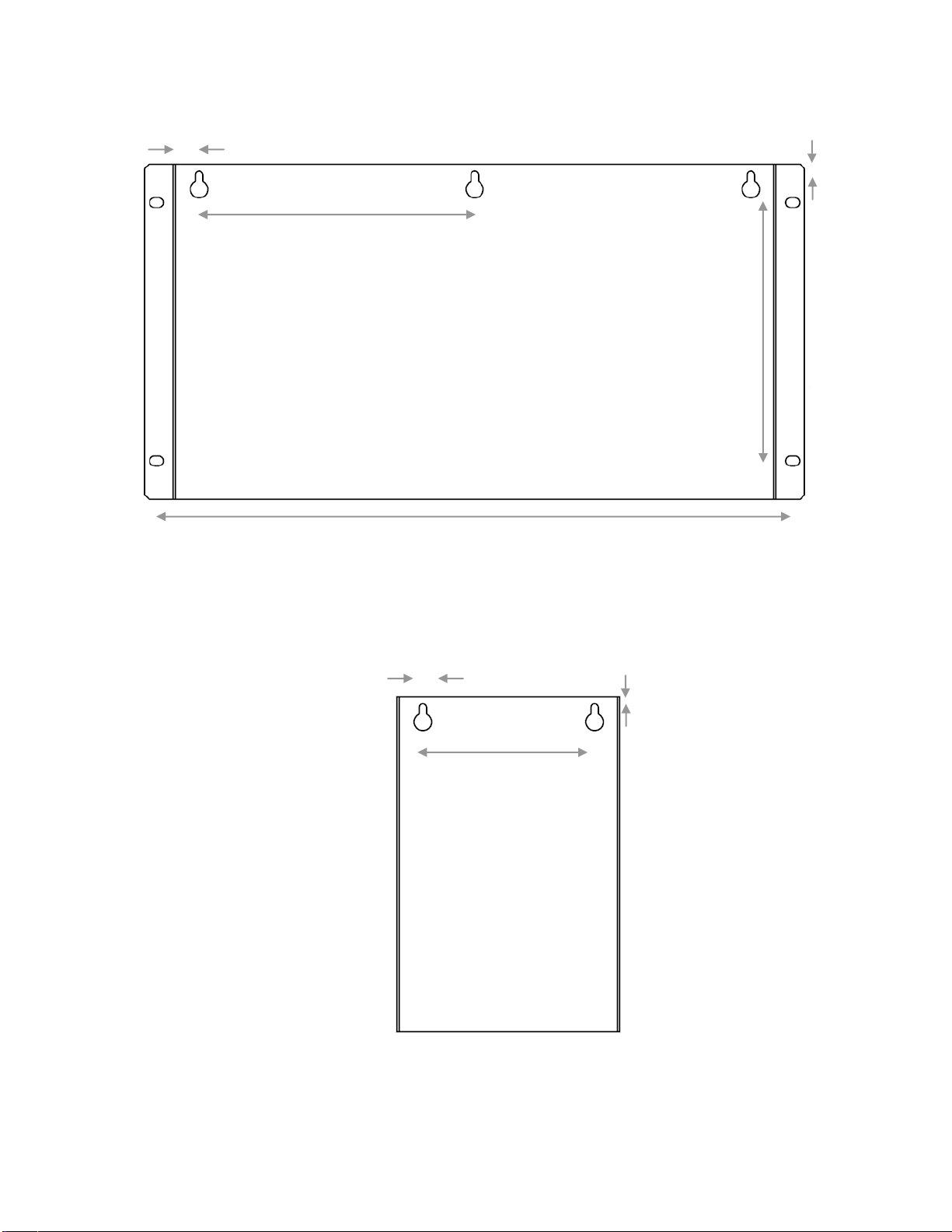
The main connector block on the front panel of the power supply (see Figure 4) connects to an 8 pin UL
approved detachable terminal block. The terminal block is provided as part of the connector kit supplied
by RTP to connect power to the RTP power supplies.
NOTE: Applying glue to the tabs or taping around the hoods of the connector kit help
keep the hoods from coming apart.
There are two pairs of input power input pins. The first pair (Pins 1 & 3) is used to supply the power
module that generates power for the RTP cards. The second pair (Pins 5 & 6) may be used to apply
power to the RTP Backplane External Voltage bus. Both power inputs are fuse protected.
The external power supply must provide a power-disconnect switch to the wires connected to the main
connector.
CAUTION! Always disconnect the external power before connecting or
disconnecting the wires to main on the power supply module.
CAUTION! Incorrect input voltage polarity or input voltage level will cause the
fuses to blow.
CAUTION! Always de-energize the external power before connecting or
disconnecting wires to the input terminal block on the chassis power supply.
When servicing the power supply (e.g. replacement of the power supply or its fuses), remove / fasten the
screws marked in red only, as shown in Figure 4. When hot-swapping a power supply in a dual power
supply chassis, it is common practice to make sure you are properly grounded prior to inserting the power
supply into the chassis.

11
Description
Pin
AC Line / DC +
1
No Connection
2
AC Neutral / DC
Return
3
No Connection
4
+ BPEXTV Input (2)
5
BPEXTV Return
6
No Connection
7
Safety Ground
8
Figure 4: Input Connection Block Pin Signals and Retaining Screw Locations.
Note: For model 3000DCPWR
and TASDCPWR, the DC Return
and the BPEXTV Return are tied
together internally. Therefore, the
24 VDC power supplies
connected to these terminals
must have a common Return.
Power ON LED

12
Planning of the I/O configuration requires careful calculation of the power required for each chassis.
Certain I/O cards require 24 VDC on the chassis backplane. The RTP Power Supply can provide this
power internally, or it can be supplied by the BPEXTV connections. To determine, if the internal supply is
sufficient, a power calculation for each chassis must be performed as shown in the Table 1: Total card
current consumption on 5 V and 24 V is calculated by multiplying the voltages with quantity within the
chassis installation (blue cells). Then total consumption for 5 V and 24 V is calculated (yellow cells). The
5 V consumption, marked with note (1) in Table 1, must be limited to 15 Amperes. If using AC main power
and if the 24 V consumption, is above 3.15 Amperes, then BPEXTV on Main Terminal Block shall be
wired also to supply 24 V externally. However, even in this situation, the total consumption of 24 V
marked with note (2) in Table 1, must not exceed 10 Amperes. The same rules apply to the 24 VDC
Power Supply module, except that the BPEXTV on Main Terminal Block must be always wired.
Table 1: Example Chassis Current Consumption Calculation in Amperes
Per Card
Total Consumed
Quantity
Description
5 V
24 V
5 V
24 V
Node Processor (3000/06)
1.75
0.00
Node/Chassis Processor (3200)
1.75
0.00
1
Chassis Processor
1.20
1.20
MODBUS TCP/IP
2.30
0.00
12-Ch. Relay Output
0.85
0.00
8-Ch. Thermocouple
0.50
0.15
0.00
0.00
8-Ch. Low Level Analog Input
0.50
0.15
0.00
0.00
8-Ch. High Level Analog Input
0.50
0.15
0.00
0.00
8-Ch. RTD
0.30
0.25
0.00
0.00
16-Ch. AC Digital Output
0.60
0.00
HART
1.40
0.00
MODBUS Serial
1.40
0.00
2-Ch. Servo Card
1.40
0.55
0.00
0.00
16-Ch. Analog Output
0.50
0.675
0.00
0.00
32-Ch. Analog / Digital Input
0.40
0.10
0.00
0.00
32/24/18-Ch. DC Digital Output
0.20
0.055
0.00
8-Ch. Counter
1.40
0.15
0.00
0.00
32-Ch. Relay Output
1.10
0.00
0.00
1
Standard Chassis Fans
0.69
0.69
Micro Chassis Fans
0.23
0.00
Total Consumed Current
1.20 (1)
0.69 (2)
AC Power Supply Current Limit
15.00
3.15
BPEXTV Current Limit
10.00
DC Power Supply Current Limit
15.00

13
Fuse Replacement
Warning! Do not remove the power supply module with external power
connected. Do not attempt to replace a fuse with external power applied to the
power supply module.
1. Electrically disconnect the external power input and BPEXTV power sources and then unplug the
main power input connector.
2. Unplug the connector to the chassis fans.
3. Unscrew the retaining screws (circled red in Figure 4) and then remove the power supply module
from the chassis.
4. Replace the fuse indicated in the charts below for your power supply.
5. Return the power supply module to the chassis, and then tighten the retaining screws.
6. Reconnect the chassis fan cables.
7. Reconnect the main power input cables.
Refer to Figure 5 and Figure 6 for the AC Power Supply fuse locations.
3000ACPWR Fuse Location
TASACPWR Fuse Location
and Fuse Type
and Fuse Type
Main AC Fuse
F3
F3
5 x 20 mm, rated 4 A / 250 V
Cooper Bussmann® type GDA-4A
Littelfuse® type 0234004.MXP
BPEXTV +24 VDC
Fuse
F4
F4
5 x 20 mm, rated 10 A / 250 V
Littelfuse® type 216010
Chassis Fans Fuse
F1
F2
Time Lag Sub Mini, rated 1 A / 250 V
Littelfuse® type 37411000410
Figure 5: 3000ACPWR Fuse Locations Figure 6: TASACPWR Fuse Locations

14
Refer to Figure 7 and Figure 8 for the DC Power Supply fuse locations.
3000DCPWR Fuse Location
TASDCPWR Fuse Location
and Fuse Type
and Fuse Type
Main DC Fuse
F1
F3
5 x 20 mm, rated 10 A / 250 V
Littelfuse® type 216010
BPEXTV +24 VDC
Fuse
F2
F4
5 x 20 mm, rated 10 A / 250 V
Littelfuse® type 216010
Chassis Fans Fuse
F3
F2
Time Lag Sub Mini, rated 1 A / 250 V
Littelfuse® type 37411000410
Figure 7: 3000DCPWR Fuse Locations Figure 8: TASDCPWR Fuse Locations

15
Fans
The RTP 3000TAS fan assembly is powered by the chassis power supply/supplies. Install the RTP
supplied cable/cables as shown to supply power to the fan assembly.
Figure 9: Chassis Fan Power Cable
I/O Cards
When you insert an I/O card, make sure that you properly align the card in the supporting card guides,
and then gently slide the card forward into the mating connector until the card seats firmly. After you
install all the cards, secure them into the chassis by installing the hold-down bracket across the top front
panels.

16
Ethernet Switches
The 3000/06 Atom Node Processors and 3200/3201 Node/Chassis Processor require industrial-quality 1-
GB TX Ethernet Switches. The 3000/01 Chassis Processors, the 3000/02-004 Modbus TCP Cards, and
Distributed I/O Cards require industrial-quality 100-Base TX Ethernet Switches. Ethernet switches must
not re-compute the packet CRCs. While the Host Ethernet switches can be managed, I/O Ethernet
switches connected to the RTP3000 TAS shall be unmanaged. RTP recommends STP Category 5 (EIA
568B, Cat 5), shielded Ethernet cables with four twisted-pair wires and RJ-45 tips. These cables are
limited to a maximum length of 328 feet (100 meters).
3000/R2 and 3100/R2 Systems
Ethernet Cabling
Table 2: Ethernet Cabling Matrix
Description
Redundant ID
Ethernet
Port
Host
Switch
A
I/O
Switch
B
I/O
Switch
C
I/O
Switch
D
Node Processor
Single (Non-redundant)
J1
X
J2
X
J3
X
J4
X
A
J1
X
J2
X
J3
X
J4
X
B
J1
X
J2
X
J3
X
J4
X
C
J1
X
J2
X
J3
X
J4
X
D
J1
X
J2
X
J3
X
J4
X
Chassis Processor
Main (00-15)
J1
X
J2
X
Redundant (00R - 15R)
J1
X
J2
X
MODBUS TCP/IP
Main (32-47)
J3
X
J4
X
Redundant (32-47)
J3
X
J4
X
2-Channel Servo
Main (32-63)
J1
X
J2
X
Redundant (32-63)
J1
X
J2
X
8-Channel Counter
Main (32-63)
J1
X
J2
X
Redundant (32-63)
J1
X
J2
X

17
Software Configuration
For software configuration the following tables are valid:
Table 3: 3000 Safety System Configuration Specifications
SIL (*)
3000 Series
CPU Nodes
Number of
Chassis
Number of Node
Processors in
Each Chassis
Number of
Chassis
Processors in
Each Chassis
Chassis
Power
Supply
Type
Number of
Available Slots for
I/O Cards in Each
Chassis
SIL-2
3000S/00-1
1
1
1
Single
17
3000S/00-1D
1
1
1
Dual
13
SIL-3
3000D/00-2
1
2
1
Single
16
3000D/00-2D
1
2
1
Dual
12
3000D/00-3
2
1
1
Single
17
3000D/00-3D
2
1
1
Dual
13
3000D/00-7
1
2
2
Single
15
3000D/00-7D
1
2
2
Dual
11
3000D/00-8
2
1
2
Single
16
3000D/00-8D
2
1
2
Dual
12
3000T/00-4
1
3
1
Single
15
3000T/00-4D
1
3
1
Dual
11
3000T/00-5
3
1
1
Single
17
3000T/00-5D
3
1
1
Dual
13
3000T/00-9
1
3
2
Single
14
3000T/00-9D
1
3
2
Dual
10
3000T/00-10
3
1
2
Single
16
3000T/00-10D
3
1
2
Dual
12
3000Q/00-11
1
4
1
Single
14
3000Q/00-11D
1
4
1
Dual
10
3000Q/00-12
4
1
1
Single
17
3000Q/00-12D
4
1
1
Dual
13
3000Q/00-13
1
4
2
Single
13
3000Q/00-13D
1
4
2
Dual
9
3000Q/00-14
4
1
2
Single
16
3000Q/00-14D
4
1
2
Dual
12

18
SIL (*)
3000 Micro
Series CPU
Nodes
Number of
Chassis
Number of Micro
Processors in
Each Chassis
Number of
Chassis
Processors in
Each Chassis
Chassis
Power
Supply
Type
Number of
Available Slots for
I/O Cards in Each
Chassis
SIL-2
3000M/00-15
1
1
0
Single
5
3000M/00-16
1
1
0
Dual
14
3000M/00-17
1
1
0
Single
18
SIL (*)
3000 Remote
Chassis
Number of
Chassis
Number of Node
Processors in
Each Chassis
Number of
Chassis
Processors in
Each Chassis
Chassis
Power
Supply
Type
Number of
Available Slots for
I/O Cards in Each
Chassis
Rack 5
1
0
1
Single
5
Rack 10
1
0
1
Single
10
Rack 13D
1
0
2
Dual
13
SIL-3
Rack 14D
1
0
1
Dual
14
Rack 17
1
0
2
Single
17
Rack 18
1
0
1
Single
18
(*) Denotes the maximum achievable Safety Integrity Level of a Safety Instrumented Function executing
in the corresponding CPU Node.

19
Table 5: 3100 DCS/PLC System Configuration Specifications
3100 Series
CPU Nodes
Number
of
Chassis
Number of
Node
Processors in
Each Chassis
Number of
Chassis
Processors in
Each Chassis
Chassis
Power
Supply
Type
Number of
Available Slots
for I/O Cards in
Each Chassis
3100S/00-1
1
1
1
Single
17
3100S/00-1D
1
1
1
Dual
13
3100D/00-2
1
2
1
Single
16
3100D/00-2D
1
2
1
Dual
12
3100D/00-3
2
1
1
Single
17
3100D/00-3D
2
1
1
Dual
13
3100D/00-7
1
2
2
Single
15
3100D/00-7D
1
2
2
Dual
11
3100D/00-8
2
1
2
Single
16
3100D/00-8D
2
1
2
Dual
12
3100 Micro
Series CPU
Nodes
Number
of
Chassis
Number of
Micro
Processors in
Each Chassis
Number of
Chassis
Processors in
Each Chassis
Chassis
Power
Supply
Type
Number of
Available Slots
for I/O Cards in
Each Chassis
3100M/00-15
1
1
0
Single
5
3100M/00-16
1
1
0
Dual
14
3100M/00-17
1
1
0
Single
18
3100 Remote
Chassis
Number
of
Chassis
Number of
Node
Processors in
Each Chassis
Number of
Chassis
Processors in
Each Chassis
Chassis
Power
Supply
Type
Number of
Available Slots
for I/O Cards in
Each Chassis
Rack 5
1
0
1
Single
5
Rack 10
1
0
1
Single
10
Rack 13D
1
0
2
Dual
13
Rack 14D
1
0
1
Dual
14
Rack 17
1
0
2
Single
17
Rack 18
1
0
1
Single
18

20
3200/R3 Systems
Ethernet Cabling
Table 6: Ethernet Cabling Matrix
Description
Processor ID
Ethernet
Port
Host
Switch A
I/O Switch
B
3200T Processor
Domain Node Rack 0
J1
X
J2
X
Domain Node Rack 0R
J1
X
J2
X
Domain Node Rack 1
J1
X
J2
X
Domain Node Rack 1R
J1
X
J2
X
Domain Node Rack 2
J1
X
J2
X
Domain Node Rack 2R
J1
X
J2
X
Domain Node Rack 3
J1
X
J2
X
Domain Node Rack 3R
J1
X
J2
X
Domain Node Rack 4
J1
X
J2
X
Domain Node Rack 4R
J1
X
J2
X
Table of contents
Other RTP Network Hardware manuals