manuals.online logo
Brands
  1. Home
  2. •
  3. Brands
  4. •
  5. RTS
  6. •
  7. Intercom System
  8. •
  9. RTS Two-Wire Intercom RM-325 User manual

RTS Two-Wire Intercom RM-325 User manual

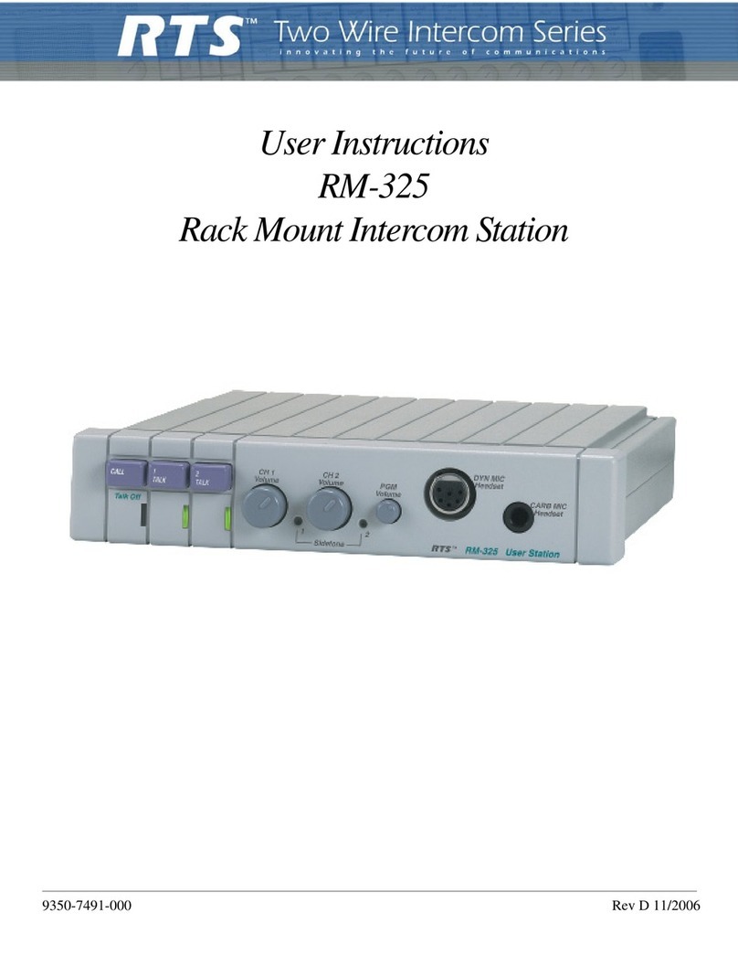
RM-325
User Station
The RM-325 is a two-channel intercom user station for the RTS-TW Intercom System. It is designed for use with a headset, and
it can be placed on a desktop, or rackmounted with optional rackmount hardware.
Talk Features
There is a separate talk button with talk-on indicator for each
channel. Talk buttons feature dual-action, momentary/latch-
ing talk operation: a button may be pressed and held to talk,
then released when nished, or the button may be tapped
once to turn talk on and then tapped again to turn talk off.
Latching operation may be independently deactivated for
each channel via an internal DIP switch. The channel 1
and 2 talk buttons may also be independently disabled via
internal DIP switches. Additionally, there is a an external talk
switch input (for footswitch etc.) for each channel via the Aux
connector.
Listen Features and Headsets
There is a separate listen volume control for each channel,
and a listen volume control for the program input. The RM-
325 accepts a stereo, dynamic-mic headset or a monaural,
carbon-mic headset. Default operation is set for stereo listen,
with channel 1 assigned to left headphone, channel 2 to right
headphone, and program input to both headphones. Inter-
nal jumpers permit all signals to be combined for monaural
listening. Internal jumpers also permit the program audio to
be assigned left or right when using a stereo headset.
Microphone and Microphone Switch Features
The Dynamic-mic headset connector features a balanced,
dynamic mic input, and a mic on/off switch input. A remote
mic on/off switch may also be connected via the Aux connec-
tor. There is an internal mic-sensing circuit for the carbon-
mic headset jack, which activates the mic circuit when the
carbon mic is on. An internal jumper can congure the car-
bon mic input exclusively for use as a mic on/off switch input
(monaural headphone output is supported in either case).
The microphone audio is available as an unswitched (hot, or
always on) unbalanced output at the Aux connector.
Talk-off (Mic Kill) Signaling
The RM-325 can send and receive Talk-off signals. Talk-off
send and receive can be independently enabled/disabled via
internal DIP switches.
Call Signaling
There is a call button and indicator, and the RM-325 can
send and receive call signals. There is also an internal setup
switch to disable call send.
Program Input
Balanced program audio may be input via the ¼-inch stereo
phone jack (PGM) or via the AUX connector.
Line/Local Power Options
By default, the RM-325 receives operating power from inter-
com channel 1. Alternatively it may be congured to receive
power from channel 2 or from a local, 24 VDC power source
connected to the AUX connector.
Sidetone
There is a separate sidetone control for each intercom
channel. These adjust the level of the station operator’s own
voice in the headphones when talking.
Features
Line Drawing
RM-325 Specications
TW System Specications
DC Operating Limits (station to power supply):
About 5,000 ft. (1.5 km) with #22 AWG wire
Audio Operating Limits (locally powered stations):
About 10,000 ft. (3 km) with low-capacitance cabling
System Capacitance:
0.3 mF, maximum (10,000 ft. [3 km] cable at 30 pF/ft.)
Intercom Channels:
Station Output Level: 0.7 Vrms (0 dBu) nominal
Channel Terminating Impedance: 200W ±5%
Station Bridging Impedance: greater than 10,000W
Current Source:
Transfer Ratio: 3.3 mA/V = 3.3 milliseconds
Output: ±5 mA into 200W, ±1 Vpeak (limiter threshold)
Call Signalling:
Send: 20 kHz ±100 Hz, 0.3 Vrms nominal
Receive: 20 kHz ±200 Hz, 100 mVrms
Talk- Off Signalling:
Send: 24 kHz ±100 Hz, 0.3 Vrms nominal
Receive: 24 kHz ±200 Hz, 100 mVrms
RM-325 General Specications
Power Requirements, Channel Powered RM-325:
30 VDC nominal (standard TW line), 45 to 75 mA
Power Requirements, Locally Powered RM-325:
24 VDC nominal, 45 to 75 mA
Environmental Requirements:
Storage: -40°C to 125°C; 0% to 95% humidity, non-condens-
ing
Operating: 0°C to 50°C; 0% to 95% humidity, non-condens-
ing
Dimensions:
1.72” (44 mm) high, 8.2” (208 mm) wide, 8” (203 mm) deep
Weight:
2 lbs 12 oz (1.23 kg)
Noise Contribution:
Less than -75 dB on the line
Common Mode Rejection Ratio:
Greater than 40 dB from the line
Program Input:
Maximum Input Level: 20 dBu
Nominal Input Level: -10 to +8 dBu
Frequency Response: 100 Hz to 12 kHz ±3 dB
Headphone Amplier
Voltage Gain: 30 ±3 dB from the line
Maximum Output: 150 mW into 50W
Frequency Response: 100 Hz to 8 kHz ±3 dB nominal
Output Voltage Level: 8 volts peak-to-peak
Headphone Impedance: 50 to 600W
Sidetone:
20 dB minimum range, adjustable
Microphone Preamplier:
Maximum Voltage Gain: 54 dB
Frequency Response: 100 Hz to 8 kHz, nominal
Input Impedance: 1,000W, balanced
Limiter Range: 30 dB
Total Harmonic Distortion:
Less than 0.2% nominal at Channel output
RM-325 Connectors
Auxiliary Connector
Type: DB-15F
Pin 1: Program input low
Pin 2: Program input high
Pin 3: Unswitched mic output high
Pin 4: Foot switch in, channel 1
Pin 5: Foot switch in, channel 2
Pin 6: Local power (+24 VDC)
Pin 7: Remote mic switch in
Pin 8: Not Used
Pin 9: Common
Pin 10: Common
Pin 11: Common
Pin 12: Foot switch channel 1 common
Pin 13: Foot switch channel 2 common
Pin 14: Local power common
Pin 15: Remote mic switch common
CARB MIC Headset Connector
Type: ¼”, 3-Conductor Phone Jack
Tip: Microphone input high (or mic switch contact
Ring: Headphone high
Sleeve: Common
DYN-MIC Headset Connector
Type: XLR-6F 6-Pin Female Audio Connector
Pin 1: Headset dynamic microphone low
Pin 2: Headset dynamic microphone high
Pin 3: Headphone and mic switch common
Pin 4: Headphone left high
Pin 5: Headphone right high
Pin 6: Remote microphone switch contact
Intercom Line Input Connector
Type: XLR-3F 3-Pin Female Audio Connector
Pin 1: Common
Pin 2: Intercom channel 1 audio and power
Pin 3: Intercom channel 2 audio
Intercom Line Loop Connector
Type: XLR-3M 3-Pin Male Audio Connector
Pin 1: Common
Pin 2: Intercom channel 1 audio and power
Pin 3: Intercom channel 2 audio
Program Input Connector
Type: ¼”, 3-Conductor Phone Jack
Tip: Program input high
Ring: Program input low
Sleeve: Common
Ordering Information
RM-325 A5F • 2 channel binaural (stereo) program-
mable modular user station • Catalog Number:
90007491000
RM-325 A4F • 2 channel binaural (stereo) program-
mable modular user station with A4M headset con-
nector • Catalog Number: 90007491001
This specications information is preliminary and is subject to change without notication.
Brand names mentioned are the property of their respective companies.
Contact Information
Telex Communications, Inc.
12000 Portland Avenue South
Burnsville, Minnesota 55337
Telephone: (800) 392-0498
Fax: (800) 323-0498
Form Number: RTS-20352-1
Date: March, 2006

Other manuals for Two-Wire Intercom RM-325

2

Other RTS Intercom System manuals

RTS KP-98 User manual

RTS

RTS KP-98 User manual

RTS WMS300 User manual

RTS

RTS WMS300 User manual

RTS BP300 User manual

RTS

RTS BP300 User manual

RTS BP-319 User manual

RTS

RTS BP-319 User manual

RTS KP-32 User manual

RTS

RTS KP-32 User manual

RTS Digital Matrix Intercom RVON-8 User manual

RTS

RTS Digital Matrix Intercom RVON-8 User manual

RTS EKP-96 User manual

RTS

RTS EKP-96 User manual

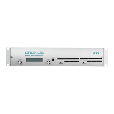
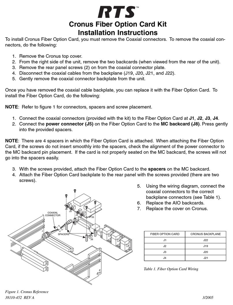
RTS Cronus Instruction Manual

RTS

RTS Cronus Instruction Manual

RTS EKP-632 User manual

RTS

RTS EKP-632 User manual

RTS IFB-828 User manual

RTS

RTS IFB-828 User manual

RTS XCP-24-USCO Quick start guide

RTS

RTS XCP-24-USCO Quick start guide

RTS Zeus III User manual

RTS

RTS Zeus III User manual

RTS WKP-1 User manual

RTS

RTS WKP-1 User manual

RTS Cronus User manual

RTS

RTS Cronus User manual

RTS Two-Wire Intercom RM-325 User manual

RTS

RTS Two-Wire Intercom RM-325 User manual

RTS XCP-40-RJ11 Quick start guide

RTS

RTS XCP-40-RJ11 Quick start guide

RTS BKP-4 User manual

RTS

RTS BKP-4 User manual

RTS WKP-1 User manual

RTS

RTS WKP-1 User manual

RTS Two-Wire Intercom Series User manual

RTS

RTS Two-Wire Intercom Series User manual

RTS EKP-32 User manual

RTS

RTS EKP-32 User manual

RTS IFB-325 User manual

RTS

RTS IFB-325 User manual

RTS MCII-e User manual

RTS

RTS MCII-e User manual

RTS WKP-1 User manual

RTS

RTS WKP-1 User manual

RTS LKP-957 User manual

RTS

RTS LKP-957 User manual

Popular Intercom System manuals by other brands

Videx VK8K Installation handbook

Videx

Videx VK8K Installation handbook

Comelit Mini 2708W/A Technical manual

Comelit

Comelit Mini 2708W/A Technical manual

Futura Digital VDT591 user manual

Futura Digital

Futura Digital VDT591 user manual

Commax DP-RS user manual

Commax

Commax DP-RS user manual

3M Audio Greeter A300 installation instructions

3M

3M Audio Greeter A300 installation instructions

Linkcom Slim IP Cam V2 user manual

Linkcom

Linkcom Slim IP Cam V2 user manual

GEV CVS 88344 manual

GEV

GEV CVS 88344 manual

Spacetronik DIO SPD-DS81 Series user manual

Spacetronik

Spacetronik DIO SPD-DS81 Series user manual

Aiphone JBW-M instructions

Aiphone

Aiphone JBW-M instructions

Smartwares DIC-222 Series instruction manual

Smartwares

Smartwares DIC-222 Series instruction manual

Channel Safety Systems ENTRitech user manual

Channel Safety Systems

Channel Safety Systems ENTRitech user manual

EJEAS F6 user manual

EJEAS

EJEAS F6 user manual

Fermax Cityline Installer manual

Fermax

Fermax Cityline Installer manual

Studio Technologies Dante 5422A user guide

Studio Technologies

Studio Technologies Dante 5422A user guide

Commax DRC-4CPN2 user manual

Commax

Commax DRC-4CPN2 user manual

FARFISA INTERCOMS Agora Mi 2495 manual

FARFISA INTERCOMS

FARFISA INTERCOMS Agora Mi 2495 manual

Comelit KCA5061 Technical manual

Comelit

Comelit KCA5061 Technical manual

Valcom VIP-429A-D-IC Assembly guide

Valcom

Valcom VIP-429A-D-IC Assembly guide

manuals.online logo
manuals.online logoBrands
  • About & Mission
  • Contact us
  • Privacy Policy
  • Terms and Conditions

Copyright 2025 Manuals.Online. All Rights Reserved.