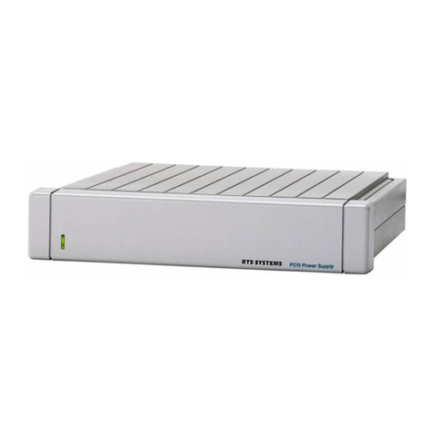
RTS RMS300 Instruction manual

TDP3504
I
OIN
9300-3504-00
Third Edition
I
September
1989
TECHNICAL DATA
PACKAGE
Rack
Mount Speaker
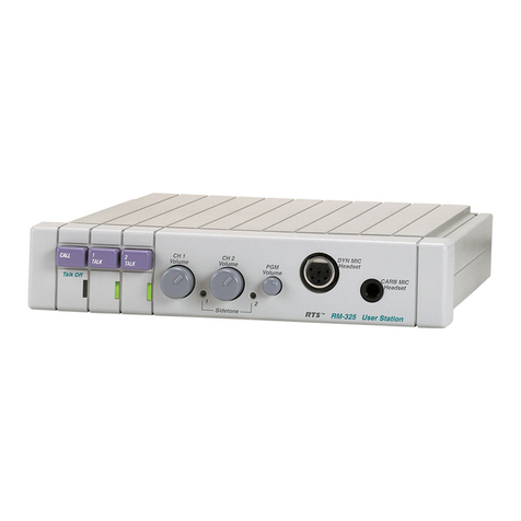
User
Station
O/N
9000-2727-00
TW INTERCOM SYSTEM
RTS SYSTEMS
A
Telex Communications Company
1100West Chestnut Street
1
Burbank, California 91506
I
Phone8181566-6700
/
FSCM:60572

TECHNICALDATA PACKAGE
Model RMS300
TW
Intercom System Rack Mount SpeakerUser Station
PROPRIETARYNOTICE
The information and design disclosed herein were
originated by and are the property of RTS Systems.
RTS Systems reserves all patent, proprietary design,
manufacturing, reproduction, use and sales rights
thereto, and to any article disclosed therein, except to
the extent rights are expressly granted to others.
COPYRIGHTNOTICE
Copyright 1988by RTS Systems, Burbank, California,
USA. All rights reserved. Reproduction in whole or
in part without prior written permission from RTS
Systems is prohibited.
PATENT NOTICE
The Model RMS300 contains and uses a design
embodied in United States Patent No. 4,358,644:
"BILATERAL CURRENT SOURCE FOR A
MULTI-TERMINAL INTERCOM". This design
employs a bilateral current source operated as a two-
wire to four-wireconverter.
TECHNICAL DATA PACKAGE,TDP 3504
Model RMS300 TW Intercom System Rack Mount
Speaker User Station
Printing History:
First Edition: September 1983
SecondEdition: October 1988
Third Edition: September 1989
Publishedby the EngineeringDepartment of RTS
Systems,which is responsiblefor its contents.
Written by: Stan Hubler
LianneSterlingSwanson
Edited by: SherylThompson
Address all communication regarding this publication
to: Director of Engineering
RTS Systems
1100West Chestnut Street
Burbank, CA 91506 U.S.A.
UNPACKING INFORMATION
AND
INSPECTION
Immediately upon receipt of the equipment, inspect
the shipping container and the contents carefully for
any discrepancies or damage. Should there be any,
notify the freight companyand the dealer at once.
The shippingModelRMS300 container should
containthe followingcomponents:
Ordering Number 9000-2727-00
RTS Systems
QQ
Part Number Description
1
9010-2727-00 ModelRMS300
1
9300-3504-00 TechnicalData Package
NOTE: Detailed informationconcerning Theory of
Operation, Maintenance, SpareParts and System
Interconnectionis availablein "The
TW
Intercom
SystemTechnicalManual", which may be obtained
through an RTS SystemsDealer or directlyfrom
through RTS Systems.
QUICK
TABLE OF CONTENTS
.
.
UnpackingInformation
....................
O.Oe~l
..
QuickTable Of Contents
...........
ooeeea.eo.e~~
..*
Warranty
...............................................
nr
Shipping Information
.........................
iii
Description
&
Specifications
............
1-1
Installation
.........................
.....oemoa.2-l
OperatingInstructions
...................
-3-1
Drawings
.........................
..
......
.4-1
RTS Systems, Burbank, CA 91506
/
FSCM: 60572 TDP3504
/
Thirdd Edition, Sept. 1989
Page ii

TECHNICAL DATA PACKAGE
Model ~~~300TW Intercom System Rack Mount Speaker User Station
RTS SYSTEMS' LIMITEDWARRANTY
The products of RTS Systems are warranted to be
free from defectsin materials and workmanship for
a period of one year from the date of sale.
RTS Systems sole obligation during the warranty
period is to provide, without charge, parts and
labor necessary to remedy covered defects
appearing in products returned prepaid to RTS
Systems, 1100 W. Chestnut Street, Burbank,
California, 91506, U.S.A.. This warranty does not
cover any defect, malfunction or failure caused
beyond the control of RTS Systems, including
unreasonable or negligent operation, abuse,
accident, failure to follow instructions in the
Technical Manual or the Owner's Manual,
defective or improper associated equipment,
attempts at modification and repair not authorized
by RTS Systems and shipping damage. Products
with their serial numbers removed or effaced are
not covered by this warranty.
To obtain warranty service, follow the procedures
entitled "PROCEDURE FOR RETURNS" and
"SHIPPING TO MANUFACTURER FOR
REPAIR OR ADJUSTMENT" listed below.
Thiswarranty is the sole and exclusive expresswar-
ranty given with respect to RTS Systems products.
It is the responsibility of the user to determine
before purchase that this product is suitablefor the
user's intended purpose.
ANY
AND ALL IMPLIED WARRANTIES,
INCLUDING THE IMPLIED WARRANTY OF
MERCHANTABILITY ARE LIMITED TO THE
DURATION OF THIS EXPRESS LIMITED
WARRANTY.
NEITHER RTS SYSTEMS NOR THE DEALER
WHO SELLS RTS SYSTEMS' PRODUCTS IS
LIABLE FOR INCIDENTAL OR
CONSEQUENTIAL DAMAGES OF
ANY
KIND.
RETURN SHIPPING INSTRUCTIONS
Procedure For Returns:
If a repair is necessary, contact the dealer where
this unit was purchased.
If repair through the dealer is not possible, phone
the RTS Systems Customer Service Department,
located at the factory, as directed below. They will
issue a
Return AuthorizationNumber.
DO NOT RETURN
ANY
EOUIPMENTTO THE
FACTORYWITHOUT FIRST OBTAINING A
RETURN AUTHORIZATIONNUMBER.
Be prepared to provide your company name,
address, phone number, a person to contact
regarding the repair, the type and quantity of
equipment, a description of the problem and the
serialnumber(s).
Questions regarding returns for repair should be
directed to: CustomerService
RTS Systems
1100
W.
Chestnut St.
Burbank
CA
91506 USA
Telephone: (818) 566-6700
Telex: 194855
Telefax: (818) 843-7953
SHIPPING TO MANUFACTURER FOR REPAIR
OR ADJUSTMENT
All shipments of RTS Systems equipment should
be prevaid via United Parcel Service or the best
available shipper. The equipment should be
shipped in the original packing carton; if that is not
available, use any suitable container that is rigid
and of adequate size. If a substitute container is
used, the equipment should be wrapped in paper
and surrounded with at least four inches of excel-
sior or similar shock-absorbing material. All
shipmentsshould be directed to the attention of the
Order Service Department and must include the
ReturnAuthorizationNumber.
Upon completion of any repair the equipment will
be returned collect via United Parcel Service or
specifiedshipper.
RTS Systems, Burbank, CA 91506
/
FSCM: 60572 TDP3504
/
Third Edition, Sept. 1989
Page iii
TECHNICALDATA PACKAGE
Model RMS300
TW
Intercom System Rack Mount SpeakerUser Station
I
?W
SYSTEM
POWER
SUPPLY
I
Figure
1-1
TW
System Concept Block Diagram
RTS Systems, Burbank, CA 91506
/
FSCM:
60572
TDP3504
/
Third Edition, Sept. 1989
Page iv

TECHNICAL DATA PACKAGE
Model RMS3OO
TW
Intercom System Rack Mount SpeakerUser Station
SECTION1: DESCRIPTION
&
SPECIFICATIONS
The ChannelSelectorSwitch selectsthe channel on
which the user
will
talk and listen.
1.1 DESCRIPTION
The headphone amplifier output drives the user's
The ModelRMS300, a Rack Mount SpeakerUser headphones.
Station, is a component used in the
TW
INTERCOM
SYSTEM. Each User Stationis a communications The Volume Control also feeds the speaker amplifier
unit along a multi-unit conferencebus. via the speaker switch and the speaker
dm
network.
The System Concept Block Diagram, Figure
1-1,
shows User Stationinterconnection, and User Station
connectionto the system power supply.
User Stationinterconnection can be: 1)centrally
wired, with each cablecoming from a central point, or
2) distributed,where all the user stationsarelooped
together from one to another, or 3) a combination of
both. The centrallywired interconnectionnot only
reduces interchannelcrosstalk,but also allows for
easier expansion into an assignablechannel, multi-
channelsystem.
The RMS3OO Block Diagram, Figure 1-2,showsuser
station functionalcomponents,input/output
connections,and controls.
The RMS3OO User Stationhas the following
functionalcomponents:
1)a microphone preamplifier with limiter
2) an electronicmicrophone switch
3) a "bilateralcurrent source"line driver
4) a listen volume control
5)
a headphone amplifier
6) a speaker amplifier
7) a speaker switch
8)
a channel selectorswitch
The microphone preamplifier/limiter
converts the small microphone signal to a strong
line levelsignal
conditionsthe signalstrengthfrom loud and soft
talkers to be almost the same
sendsthe signalto the line via the microphone switch
and a "bilateralcurrent source".
The bilateral current sourceadds signal,via the
channelselect switch, to the line without affecting any
signals already on the line. The bilateral current
sourcealso extracts the listen signalfrom the line and
sendsit to the headphoneamplifier via the volume
control. Someof the user's own voice signal
("sidetone")is also fed to the headphone amplifier.
The user station voltageregulator takes power from
channel
1,
regardlessof the channel selector switch
setting (exception: localpower option units). The
regulator not only supplies regulated power to the
user station,but also prevents unwanted interaction
between the user station and theat intercom line
which is supplyingthe power. Because the regulator
takes power from channel
1,
channel 2 can be
expanded into many channelsby using a switch and,
for each channel, a separatewire and a termination
network consistingof a 200 ohm resistor and a 10
microfarad capacitor in series. (See theApplication
Diagrams
in
the
TW
Intercom SystemsTechnical
Manual).
A
TW
System Power Supplyterminates a line with
200 ohms.
1.1.2 Operational Controls
The RMS300 User Station has the following controls,
described and shown in Section
3:
1) ChannelSelectSwitch
2) Latching-actionMICrophone ON-OFF toggle
switch.
3) Momentary-action MICrophone ON-OFF
pushbuttonswitch.
4) SpeakerlHeadphone VOLUME Control
5) CALLLIGHT switch/indicator
6) SPeaKeR ON/OFF switch
7) SIDETONEAdjustment
1.13 Connection, Inputs and Outputs
The RMS300 User Station has four input/output con-
nectors:
1) DYNamicMICrophone type HeaDSeT or handset
2) CARBON MICrophone type headset or handset
3) Line INPUT (ties the station to the intercom line
4) LOOP/EXTension (allows another station to
access the line through the first station. Also called
loop-through.)
RTSSystems, Burbank,
CA
91506
/
FSCM: 60572 TDP3504
/
Third Edition,Sept. 1989
Page
1-1

TECHNICALDATA PACKAGE
Model RMS300
TW
Intercom SystemRack Mount SpeakerUser Station
LINE IN
LINEIEX1
Figure
1-2
RMS300
Block
Diagram
RTS Systems, Burbank, CA 91506
/
FSCM: 60572 TDP3504
/
Third Edition,Sept. 1989
Page
1-2

TECHNICALDATA PACKAGE
ModelRMS300
TW
IntercomSystem Rack Mount SpeakerUser Station
1.2
MODEL RMS300 SPECIFICATIONS
OVERALLSYSTEM SPECIFICATIONS
AudioLine Voltage, Nominal
1
volt, peak (0 dBm voltage-equivalent)
AverageSpeechLevel Range -20 dBV to -10 dBV
AbsoluteMaximum Speech Level 3 volts, peak (linear limit)
AudioLine Impedance,Nominal 200 50 ohms, 75Hzto 20kHz
Systemwill continueto operate from 50 ohms to300 ohms
System DC Line
Voltage
Nominal
OperationalRange
Steadystate without damage
Transient
System DC Current
Quiescent (per station)
Dynamic (per station)
Start-Up Current
~aultCurrent
Operating Distances
Maximum DC limit
Maximum AC limit
System Capacitance
32volts DC
18to 35volts DC
-1.5 volts to
36
volts DC
200 volts,
8
millisecondsor less (after this time, power supply and
user stationfuseswill open)
10to
40
milliamps
50 milliamps (w/25 ohm headphones)
70 milliamps (w/25 ohm headphonesand lights)
100milliamps (w/8 ohm speaker)
1.25amperes, 50 units,
all
kinds
4.0 amperes,power supplyatvoltage
>
12volts
1.0 amperes,power supplyat voltage
<
12volts
5,000 ft. distance alongcable, power supplyto single station #22
gaugewire -DCvoltage drop limitation
10,000 ft. drypair, power supplyat each end, #22 gaugewire
0.3 microfarads (cumulativeeffect of 10,000ft. of Maximumcable at
30 picofarads/foot)
RTS Systems,Burbank, CA 91506
/
FSCM: 60572 TDP3504
/
Third Edition,Sept. 1989
Page 1-3

TECHNICAL,DATA PACKAGE
Model RMS300
TW
Intercom System Rack Mount Speaker User Station
USER STATION SPECIFICATIONS
Input DCvoltage:
DC Current
Impedance across line:
Ambient Temperature Range
Noise contribution
to 200 ohm line:
Microphone Preamplifier
Input impedance*
SourceImpedance*
Maximum Input Level*
Voltage gain:
FrequencyResponse
Limiter range
Carbon MicExcitation Current
20 to35volts DC, operatingfrom -200 to +36 volts DCwithout
damage
Quiescent,10to
40
milliamps
50 milliamps, typical (w/25 ohm headphones)
75 milliamps, typicall (w/25 ohm headphones
+
light)
100milliamps, typical(w/8 ohm speaker
10,000 ohms typical; ohms worst casedynamicoperation
Operating: 0 C to
60
6
Storage: -55 C to 125
6
One Unit: -75 dBu
Ten Unit: -67 dBu
470 ohms
200 ohms, nominal
150millivolts
54 dB
100Hz to 10,000Hz, 3dB
50 dB
10milliamps, nominal
"DynamicMicrophoneInput
Current Source
Transfer ratio:
Output:
Headphone Amplifier
Overall voltage gain
Overall voltagegain
Output power:
FrequencyResponse
HeadphoneImpedanceRange
SidetoneAdjustment Range
Call Light:
Dimensions
5 milliamps/l.5 volts
5 milliamps into200 ohms
24 dB
9volts peak-to-peak into25 ohms
Headset station: 112watt into 25 ohms
SpeakerStation: 2 watts into 8 ohms
150
Hz
to 8,000 Hz,
3
dB
25 to 600 ohms
20 dB to full on
Signaling Frequency 20,000 kHz
3
dB
FlashingRate 5Hz 2Hz
3.468" H x 1.5"
W
x
3.0
D
13.21
x
3.81
x
7.62 centimeters
RTS Systems, Burbank, CA 91506
/
FSCM: 60572 TDP3504
/
Third Edition,Sept. 1989
Page 1-4

TECHNICAL DATA PACKAGE
ModelRMS3OO TW Intercom System Rack Mount Speaker User Station
r1
SECTION
2:
INSTALLATION
2.1
MECHANICALINSTALLATION
The ModelRMS300 mounts in an
EIA
standard 19-
inch equipment rack/enclosure, and is one rack unit
high. Allow a minimum of 4 inches (101.6 mm) for
the panel microphone and controls in front.
Additional depth should be allowed for the cabling in
the rear. There arenoventilationrequirements.
2.1.1
Headset Requirements
Dynamicmicrophoneheadset type:
50 to 1000ohm microphone
25 to 1000ohm headphone(s)
High efficiency headphones are recommended be-
cause less line current is required from the power
supply. Use headphones with an impedance of 25
ohms or greater. Low impedance 8 ohm headphones
are not recommended. Headphones with good
acoustic isolation (20 to 40dB) improve communica-
tion
in
high
ambient noise environments, and allow
the user to use the headphones at a less tiring, lower
i\
volume.
\d
In the headset connecting cable, prevent coupling
between the microphone and headphone leads by us-
ing a shielded, twisted pair for the microphone, and a
separate, twisted pair for the headphones. Do not
allow headphone ground to contact microphone
ground or shield. Tie the shield to microphone
ground or "miclow". The headset cable can be made
longer when the microphone and headphonepairs are
physically separated. The wider the separation, the
longer the cable length which may be used. Esti-
mated maximum usable headphone cable lengths are
as follows:
Singlecable,
Two shielded twisted pair: 10ft. (3 m).
Dual ribbed cable,
Two shielded twisted pair: 30 ft. (9 m).
22
ELECTRICAL
22.1
Power
The RMS300 receives electricalpower from either:
(1) a system power supply (26 to 32volts DC on line
connector pins 2
(+)
and
1
(com) (1 or two channel
operation); or
(2) a local power supply option (14 to 26 volts DC).
A
user station requires
18
to 33 volts to be a 10,000
ohm bridging impedance across the powering line, but
the station can otherwise operate (as in the local
power option) from 12to33volts.
When using a local power supplyoption, each channel
requires a 200 ohm load. See Figure
1-1.
It is
necessary to do this only once for each channel string.
Model RMS300 current requirements range from 30
to 100
mA,
Since, in (I), above, the power and
communications signals may share conductors, it may
be necessary to overcome power losses by increasing
conductor size over long runs (over 1/2 mile (804
m)). Typical operating distance for one RMS300
station is 1/2 mile (.80
km),
and for one RMS300-L,
1/3
mile (0.53 km) using a normal
#
22
AWG
conductor size.
22.2
Signal
The required number of conductors to interconnect
user stations is as follows (For standard unbalanced
TW
user stations):
#
of Channels
#
of Conductors
*
Using a TW power supply (and possibly
operatingon a
TW
system).
**
Using
a
non-TW power supply.
***
Using a
TW
power supply and operating on a
TW
two channelsystem.
RTS.Systems,Burbank, CA 91506
/
FSCM: 60572 TDP3504
/
Third Edition, Sept. 1989
Page 2-1

TECHNICAL DATA PACKAGE
Model RMS300
TW
IntercomSystem Rack Mount Speaker User Station
Use shielded cableto interconnectuser stationsin ar-
eas of possible electrical interference, (areas such as
those near: digital equipment, high current primary
power conductors ("mains"), transformers, transmit-
ters, and lamp dimmers).
Most two channel applications may use either stan-
dard microphone cable (for convenience) or two-
twisted-pair cable (considerably less expensive than
microphone cable). Standard wire size for the
TW
Intercom System is #22 gauge wire for interconnec-
tion. For permanent installationsit is recommended
that each channel should have individually shielded
twisted pair of at least #22 gauge wire, such as
Belden #8723 for 2 channels. Connect the shield to
system common
but do not tie the shield to chassis,
earth orconnector shell ground.
223 Crosstalk Control
In the
TW
Intercom System all channels share a
common circuit ground return. Crosstalk due to
common ground resistance can be lowered by re-
ducing the common ground resistance. Reduction of
ground resistance can occur as a side benefit of using
shielded cable, since the shield drains can be tied to-
gether and electrically parallel the circuit ground.
Another way of lowering resistive crosstalk is to
"homerun" all interconnecting cables to a central or
"home" location. In this configuration, the ground
path is short and the correspondingground resistance
is small. Crosstalk due to mutual capacitance occurs
when the signal on one wire of a twisted pair couples
into the other wire. Separating the two conductors
with a shield greatlyreduces the capacitivecrosstalk.
To reduce both capacitive and resistive crosstalk and
to afford a degree of RF and electrostatic shielding,
use a cable which has a shielded twisted pair for each
channel. Each pair consists of a conductor for the
channel, a conductor for circuit ground return and a
shield around the two conductors. The shield is ac-
cessed via a drain conductor. This drain conductor
and the shield can augment the circuit grounds and
thus lower the ground resistance.
cable connectors are lifted out of the mud or snow
and protected with plastic bags. Water, mud and
snow in connectors can cause considerable audible
noise.
2.2.5 Hlam Prevention
Prevent inducing hum into the system by not locating
user stations near hum sources such as power
transformers, electrical switch panels, lamp dimmers
or TV cameras. When the microphone switch is
turned on, the dynamicmicrophone acts as a sensitive
antenna for hum sources.
2.4 USER STATION CONNECTIONS
DynamicMicrophoneheadset connector:
XLR-4-31type receptacle (Jl)
Input level: -55 dbu nominal
Output Ievel to headphone: 10 volts peak-to-peak
open circuit.
Pin
1
-
Microphonelow
Pin
2
-
Microphonehigh
Pin 3
-
Headphone low
Pin 4
-
Headphone high
Carbon Microphone headset connector: Standard
114" PhoneJack (52)
Input level: -15 dbu nominal
Output to Headphone: 10 volts peak-to-peak open
circuit.
Tip
-
Carbon Microphone
Ring
-
Headphone
Sleeve
-
Common/ground
Line input connectors: (53154)
XLR-3-31/32 types (for two-channels)
Pin
1
-
Common (low sideof line)
Pin2
-
Channel
1
Pin 3
-
Channel2
Routing the TW Intercom System cables along the XLR-4-31/32 types (for three-Channels)
same ductways and pathways as power cablingcan in-
crease the noise and hum levels. Pin
1
-
Channel
1
Pin 2
-
Channel2
22.4 Moisture
/
Contamination Protection
Pin 3
-
Channel3
Pin 4
-
Common (low sideof lime)
When using equipment in the rain, always protect the
equipment with plastic covers----also, make sure all
RTS Systems, Burbank, CA 91506
/
FSCM: 60572 TDP3504
/
Third Edition,Sept. 1989
Page2-2

TECHNICAL
DATA
PACKAGE
Model RMS300
TW
IntercomSystemRack Mount SpeakerUser Station
This page intentionallyblank
RTS Systems,Burbank,
CA
91506
/
FSCM: 60572 TDP3504
/
~hirdEdition, Sept. 1989
Page 2-3

TECHNICAL
DATA PACKAGE
Model RMS300 TW IntercomSystem Rack MountSpeakerUser Station
Figure
3-1
Model
RMS'3OO
Front Panel
RTS Systems,Burbank, CA 91506
/
FSCM: 60572 TDP3504
/
Third Edition,Sept. 1989
Page
2-4

TECHNICAL DATA PACKAGE
Model RMS300
TW
Intercom System Rack Mount Speaker User Station
SECTION
3:
OPERATION
3.1
OperatingControls
(See Figure 3-1)
Table 3-1below lists the Model RMS300 operatingcontrols. The reference numbers in Table
3-1
correspond
to the circled numbersin Figure 3-1.
Ref.
No.
-
Name
Table 3-1
Descrivtion
1
Channel SelectSwitch
Selects one of two channels (standard) or one of three channels (optional).
The Call Light Option transmitter and receiver operate on the channel
selectedby this switch. The CHannel SelectSwitch is omitted in the Single
Channel (SC) option.
2
MIC ON-OFF Toggle
A
latching-actionswitch. Turning on the microphoneslightly"dims"or
attenuates the speaker.
3
MIC ON-OFF
A
momentary-actionpushbutton switch. Not standard with the
Call
Pushbutton
Light Option. Turningon the microphonehere also slightly"dims"or
attenuates the speaker.
4
VOLUME
A
speakerlheadphone volume control. Maybe a dual control for the Dual
f\
Listen (DL) or Program (E) Option.
CAUTION: ALWAYS
TURN
THIS CONTROLALL THEWAY
COUNTERCLOCKWISE(TO THE LEFT) BEFORE PLUGGING IN
THE HEADSET.
Call Light
This switch/indicator appears in place of the MIC ON-OFF
Indicator
PUSHBUTTON (#3) on user stationswith the "CallLight"option. When
Switch
depressed,this switch adds a 20 kilohertzsignal to the
TW
intercom line
on the same channel that the CHannel SelectSwitchhas been set. This
signal activatesthe Call Light receiver on
all
user stationswhich are
switched to the same channel.
SPeaKeRON/OFF
Thisswitch: 1)turns on the speaker,2) disables the headset microphone
and 3) enablesthe panel microphone.
SIDETONE
The screwdriver-adjustedSIDETONE controlsets the "sidetone"
level during headset operation and sets the "balance"nulling during
speakerlpanelmicrophone operation.
To adjustthe SIDETONE controlfor speaker operation: 1)turn ON the SPeaKeR switch, 2) turn
ON the MICrophoneswitch, 3) set the VOLUME controlto about 50%, 4) hum into the panel
microphone and adjustSIDETONEfor minimum sound through the loudspeaker.
To adjust the SIDETONE control for headset operation: 1) turn OFFthe SPeaKeR switch, 2) turn
ON the MICrophooneswitch, and 3) plug in a headset, 4) set the VOLUME control to about 50%,
5)
turn the SIDETONE controlfully counterclockwise, the adjust it clockwise for a comfortable level
of your own voice while talking into the headset microphone.
RTS Systems,Burbank,
CA
91506
/
FSCM: 60572 TDP3504
/
Third Edition,Sept. 1989
Page3-1

Installation. Local Power Option. RMS300 and
SPK308
The RMS300 and SPK300 can be powered from an external (local)
powes supply of between 18 to
33
volts
DC,
The
local power
option, as supplied by RTS Systems uses a power supply assembly
(RTS #9020-4425-OO), which is
117
VAC 60
Hz
in,
24
VBC
400mA
out
To modify the RMS300 or SPK300 for local power operation:
1. Remove diode
D26
from the CC3QO P.
(2.
beard.
2.
Add J6, 4 pin
jack
(Calrad #38-454, RTS #2013-0005-001,
to the back panel. Wire as
shown
in the diagram below.
Pin 1= common, Pin 2= external supply
+
(18
to
33
VDC).
3.
Wire P6, 4 pin plug (Calrad #30-453, RTS #2013-0016-00)
to the external supply: Pin 1- common, Pin 2= external
supply
9.
Plug P6 into
J6
on the RMS300 or SPK300 back
panel, Note:
If
using RTS local power option kit
9002-5541-00, the external supply
will
already
be
wired
to P6.
Local. Power
(Back Panel)
#22
AWG
Wire
'
000
0000
+12
8
9
10
Remove
~26-
CC300 P-C-Board

When a system is constructed using locally powered user
stations, it is essential that all channels are terminated with a
200 ohm system termination. System terminations include:
1)
An
RTS Systems
TW
power supply*,
2)
A
discrete 200 ohm resistor for each locally supplied
channel,
3)
When application
of
a B.C. voltage is expected or
possible, a 10 microfarad/
50
volt capacitor in series with
the
280
ohm resistor for each locally supplied channel.
See diagram below.
Termination
To
other
user
stations
A1
ternate
Termination
Phase
%%I
Phase
11%
I I
Power. Power
m
*Examples
of
RTS Systems power supplies are: PS8, PS10, PS30,
PS31,
PS50,
and PS60.

TECHNICAL DATA PACKAGE
Model RMS300
TW
Intercom System Rack Mount SpeakerUser Station
SECTION
4:
DRAWINGS
RTS Svstems
-
Document
Number
ServicingDiagram, Light SignalingCircuit CC285
ServicingDiagram, Model RMS3001SPK300
SchematicDiagram, CC300, page 1of 3
SchematicDiagram, CC300, page
2
of 3
SchematicDiagram, CC300, page 3 of 3
Wiring for ExternalMicrophones
Wiring Diagram, pg.
1
of 11
SPICJRMS300Standard-L Option and Local Power Option
Wiring Diagram, pg.
2
of 11
SPKJRMS3003CH and 3CH-L Options
Wiring Diagram,pg. 3 of 11
SPK/RMS300-DL
Wiring Diagram, pg.
4
of
11
SPKJRMS300, IFB Option
Wiring Diagram, pg. 5 of 11
SPICJRMS3OO-DL-3CH
Wiring Diagram, pg. 6 of 11
SPKJRMS300Program Input Option
Wiring Diagram, pg.
7
of 11
SPKJRMS300DL (Dual Listen)
-
E
(Program Input)
Wiring Diagram,pg.
8
of 11
SPICJRMS300-USM-B
Wiring Diagram, pg.
9
of 11
SPKJRMS300-VI-3CH-VI
Wiring Diagram,pg. 10of 11
SPKJRMS300-DL-MSG
Wiring Diagram, pg. 11of 11
SPKBMS300Program Input and USMB Options
RTS Systems, Burbank, CA 91506
/
HCM: 60572 TDP3504
/
Third Edition, Sept. 1989
Page
4-
1


FROM CHANNEL
SELECT SWITCH
(CH.l)
FROM CHANNEL
SELECT SWITCH
(CH.2)
NOTE: UNIT MUST BE LOCAL POWERED
CH.1 HI
CH.1 LO
CH.2 HI
CH.2 LO
CHASSIS GND
,
.
I
I
8
E
DL-VI OPTION
USM
600:600
--
,--
:
NOTE: NOT FOR USE WITH DL OPTION
L_-________________-----------------------
26 IN UNITS WITH CALL LIGHT OPTIONS (-L). MOMENTARY
O
-
MIC SWITCH IS NOT INSTALLED.
FOOT SWITCH OPTION (FS)
J7
p7
CALRAD 130-456
:
FOOT SWITCH
:
RTS MODEL FS-1
CHANNEL
SELECT
SWITCH
J2
P2
C47 (REF) (REF) (REF)
SWlP3T
CH.~
lOOK
(REF)
-----------------------------------------------.-------------------.
LICON
05-135 LM9003
3
;;
IF, IN
i
;:
IFB OUT
/
&.-,-""-
j
TO USM
,------------------------------------~~~
I
I
:
-VI
OPTION (UNITS WITHOUT
j
i
l
OCAl POWER (LP) OPTION DL OPTION)
!
:-------------------------------------------------------------:----------------------------------------J
!
:
J6 P6
CALRAD 130-454 CALRAD N30-453
TO LP SUPPLY CONTROL
PANELS S4
I
NO CONNECTION (CHANNEL SELECT
i
!
:
SWITCH)
25 FOR 3CH-DL OPTION: REMOVE W2 WHEN AUX. LISTEN IS SET TO MONITOR
O
CHANNEL 1. REMOVE W4 WHEN AUX. LISTEN IS SET TO MONITOR
CHANNEL 2. CUT TRACE BETWEEN U4-3
&
L3 WHEN AUX. LISTEN IS SET
TO MONITOR CHANNEL 3.
I
I
24 IN UNITS BUILT PRIOR TO 1-3-88. THE CARBON MIC WAS ACTIVE IN BOTH
O
THE "PANEL"
&
"HEADSET" SWITCH POSITIONS. IN UNITS BUILT AFTER
-
3-1-88. THE CARBON MIC IS ACTIVE ONLY IN THE "HEADSET" POSITION.
I I
FOR LOCAL POWER OPTION. REMOVE 026.
CUT TRACE FOR SQUAWK OPTION. ADD JUMPER BETWEEN SQ1
&
SQ2.
FOR SQUAWK OPTION. CHANGE R99 TO 10K.
CUT TRACE FOR E (BALANCED PROGRAM IN) OPTION. SQUAWK OPTION.
ON 3-CH (3-CHANNEL) OPTIONS. SEE DETAIL FOR PIN OUT OF
INPUT
(J3)
AND LOOP/EXT (J4) CONNECTORS.
18
FOR E (BALANCED PROGRAM IN). SQUAWK OPTIONS: JMP2 IS JUMPERED
O
TO JMPE. DELETE JUMPER FROM JMPl TO JMPP.
17. FOR DL-VI OPTION (DUAL LISTEN WITH VIDEO ISO). JUMPER TCl TO LCI
ALTERNATE PIN OUT NOTED FOR 7307 I.C. (APPLIES TO UNITS
MANUFACTURED PRIOR TO JANUARY. 1984).
DELETE P2 FOR 2-WIRE BALANCED OPTION.
CUT TRACE FOR 2-WIRE BALANCED OPTION.
JUMPER P1 TO
81 &
P2 TO 82 FOR DL (DUAL LISTEN) OPTION.
CHANGE R24 TO 22K FOR DL (DUAL LISTEN) OPTION
&
SQUAWK OPTION.
REMOVE
FOR
DL
(DUAL
LISTEN)
OPTION.
SQUAWK
OPTIONS.
CUT TRACES FOR DL (DUAL LISTEN) OPTION.
REMOVE R34 WHEN USING R33.
8. CUTTABLE TRACES ARE SHOWN
+.
7
ON STANDARD SPK UNITS. PANEL MIC IS DELETED. R15 REMOVED.
O
AND S1A JUMPERED N.C. TO N.O.
-
6 SPK UNITS HAVE T5 INSTALLED.
RMS UNITS HAVE JUMPERS ACROSS T5 PADS AS SHOWN BY
DASHED LINES. (T5 IS DELETED).
5
IN THE STANDARD CONFIGURATION U3.U4.U5,U7.U8
&
U10 ARE NOT USED.
U3 PINS 5.6
dc
7 ARE JUMPERED TOGETHER. JMPl IS JUMPERED TO
JMP2. AND Bl IS JUMPERED TO PI.
I
I
4 R31-CHANGE TO 10K WHEN U3 IS INSTALLED (DL.E.
&
0
SQUAWK OPTIONS).
3
THESE PARTS ARE ALTERNATE BIAS NETWORK FOR ALTERNATE
0
CONDENSER MIC. REMOVE R3
&
C1 WHEN USING THIS NETWORK.
2.
CAPACITANCE VALUES ARE SHOWN MICROFARADS/VOLTS.
1.
ALL RESISTORS ARE CARBON FILM. 1/4 WATT. +/-5%.
N
0
T
E
S:
UNLESS OTHERWISE SPECIFIED
I
I
CONTRACT NO.
300
RTS
SYSTEMS
Burbank. ~a~ifornta
Drawn
R.NFILSON SCHEMATIC DIAGRAM
.
CC-300 FOR
Checked SPK-300
.
RMS-300
I
Issued
ISIZE
I
FSCM
I
DWG NO
IREV
I I
D
1
605721
8
I
7
I
6 1
DATE
8-18-89
~~27121
AG
5
I
4
I
3
I
2
I
S2712002 I9HFFT 20f
3
1


Other manuals for RMS300
1
Table of contents
Other RTS Intercom System manuals