RTX RTX4069 User manual
English
1
wirElEss iP DECT/wlAn
BAsE sTATion
(MoDEl: rTX4069)

English
2
DEAr CUsToMEr
This publication explains the steps for initial setup and configuration of the Base Station. It also provides
troubleshooting information and detailed specifications.
Copyright © 2007 RTX Network Systems. All rights reserved. All forms of copying or reproduction of the prod-
uct are strictly prohibited.

English
3
TABlE of ConTEnTs
DEAR CUSTOMER .......................................................... 2
SAFETY/ WARNINGS........................................................ 4
OVERVIEW ................................................................ 4
INITIAL SETUP ............................................................. 5
Unpacking the Base Station.................................................. 5
Package Contents ..................................................... 5
User-Supplied Equipment ................................................ 5
Opening the Housing....................................................... 5
Connecting the Base Station to:............................................... 7
(1) Sync Unit ......................................................... 7
OR
(2) Ethernet Sync/Switch Unit............................................. 9
WLAN Card (Optional) ...................................................... 11
LED and DIP Switch Functionality .............................................. 12
VDSL Connection ...................................................... 12
Ethernet Connection ................................................... 12
PLACEMENT AND LIGHTNING PROTECTION................................... 16
TECHNICAL/PHYSICAL CHARACTERISTICS .................................... 18
ANATEL HOMOLOGATION .................................................. 19

English
4
WARNING: Only qualified personnel should handle this Base Station.
WARNING: Do not work on the system or connect or disconnect cables during periods of lightning activity.
WARNING: Read the installation instructions before you connect the system to its power source.
WARNING: The system, including antennas, is TNV-2 (72 volts) and must be electrically isolated from the supply
source.
WARNING: The system must be used in conjunction with a Sync Unit or Ethernet Sync/Switch Unit.
WARNING: Hazardous network voltages are present in this device, regardless of whether power to the Base
Station is OFF or ON. To avoid electric shock, use caution when working near the Base Station.
WARNING: Ultimate disposal of this Base Station should be handled according to all national laws and
regulations.
sAfETy / wArnings
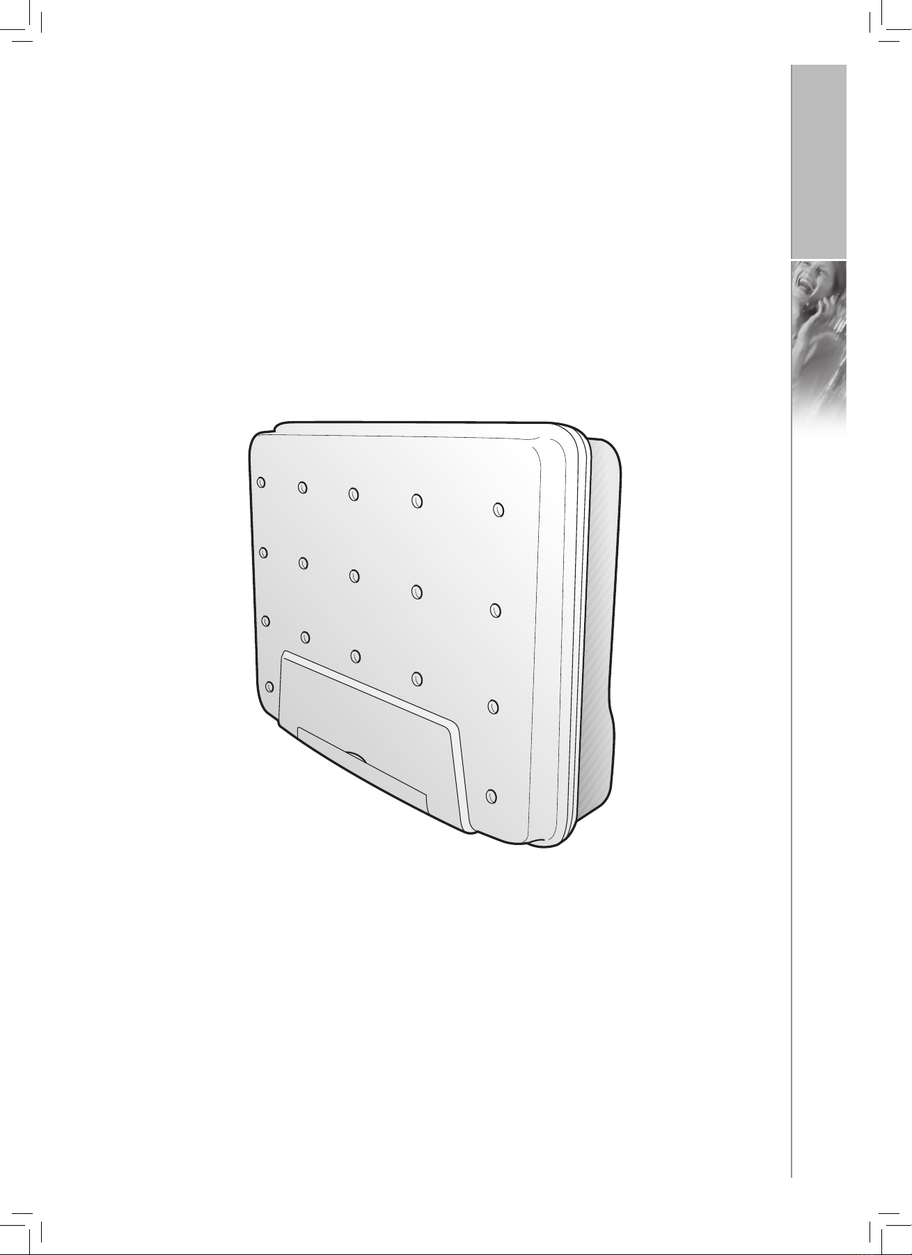
ovErviEw
The Base Station is a combination DECT Base Station and WLAN Access Point with an up to 11-channel radio
transmitter/receiver. It is designed for use with the wireless IP telephony broadband data access services.
To cover large areas with low populations concentrated in clusters such as in villages, a setup with one Ethernet
Sync/Switch Unit and as many as 6 Base Stations mounted in clusters on towers or pylons is recommended.
The cluster will be synchronised to a GPS via the Ethernet Sync/Switch Unit. The connection to the IP network will
be via Ethernet and the connection to the Sync /Switch Unit will also be via Ethernet.
For distribution in areas with high-density populations, as many as 24 Base Stations can be used with a Sync
Unit via a VDSL/SYNC connection, mounted, for example on street lampposts.
The Base Station can be used with a choice of antennas, depending on the required gain and directivity:
• dipole (omnidirectional, 2-4 dBi)
• patch (10.5 dBi)
• external antennas for improved gain
If the external antenna option is chosen an External antenna kit is required, RTX item no. 95101873
Using DECT repeaters extends the range of each Base Station and enables access to areas shielded from the Base
Station.
English
5
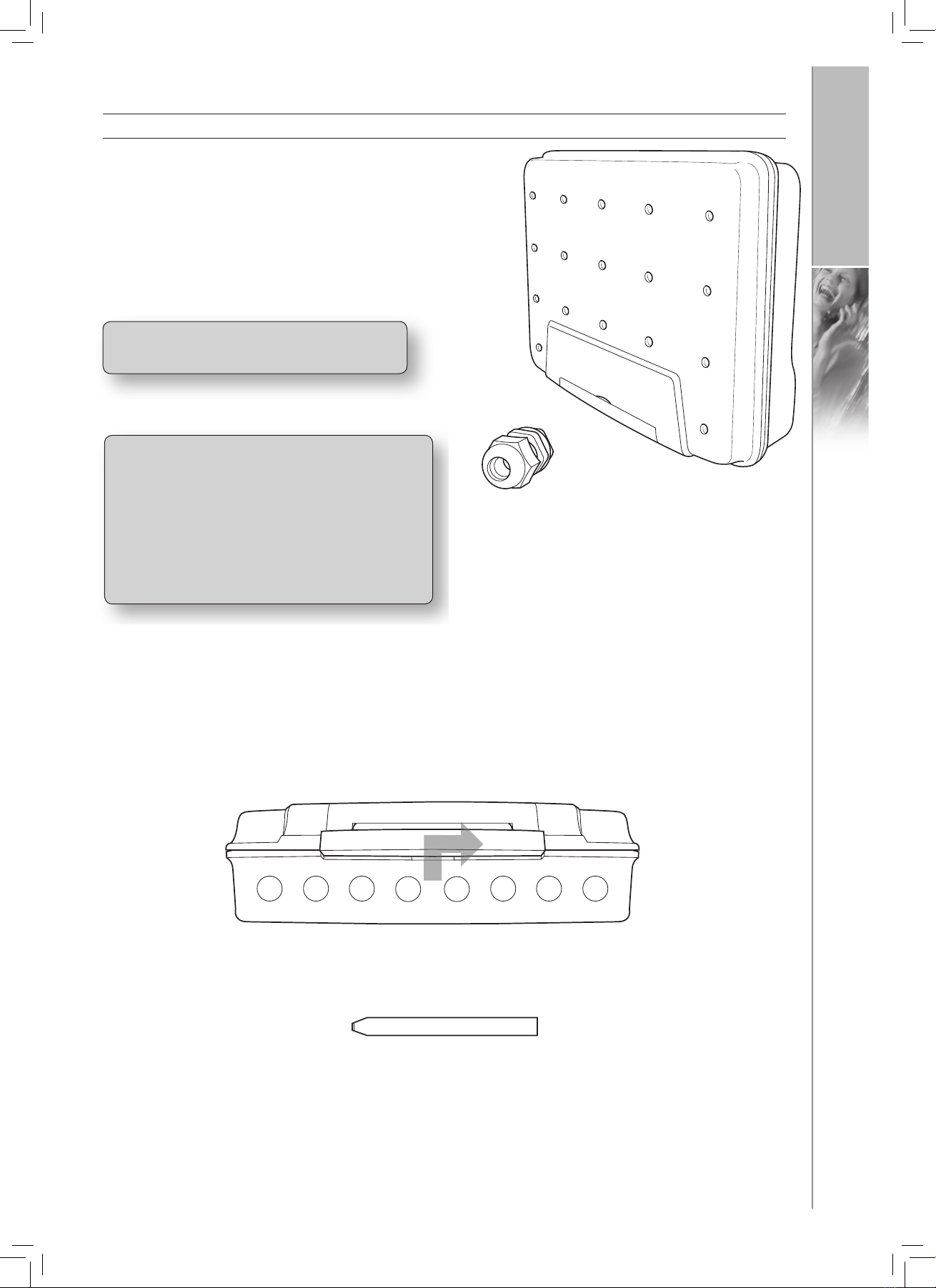
UNPACKING THE BASE STATION
Package Contents
Each Base Station is shipped with the following items:
• Housing
• Cable gland
NOTE: If any item is damaged or missing, please
FIG. 1:
OPENING THE HOUSING
To open the housing:
1) Push the slider under the frontpiece to the right with the tool supplied (separately, one per pallet).
FIG. 2:
iniTiAl sETUP
Note: If other cable glands than the ones
supplied with the Ethernet Sync-Switch Unit are
used then these must be non-inflammable
type of either:
V1
•
or
Gland Jacob part #50.616 PA7001 and
•
nut Jacob part #50.216 PA7001
English
6
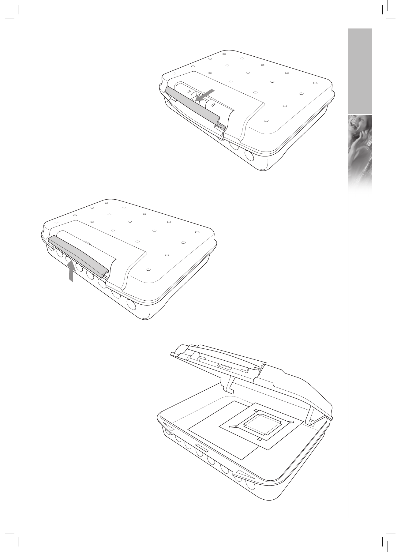
2) Pull forward the upper section.
FIG. 4:
4) Raise the lid. It will click, and is locked open at 90°.
3) Unclip the lower section of the pivoted
frontpiece.
FIG. 5:
FIG. 3:
English
7
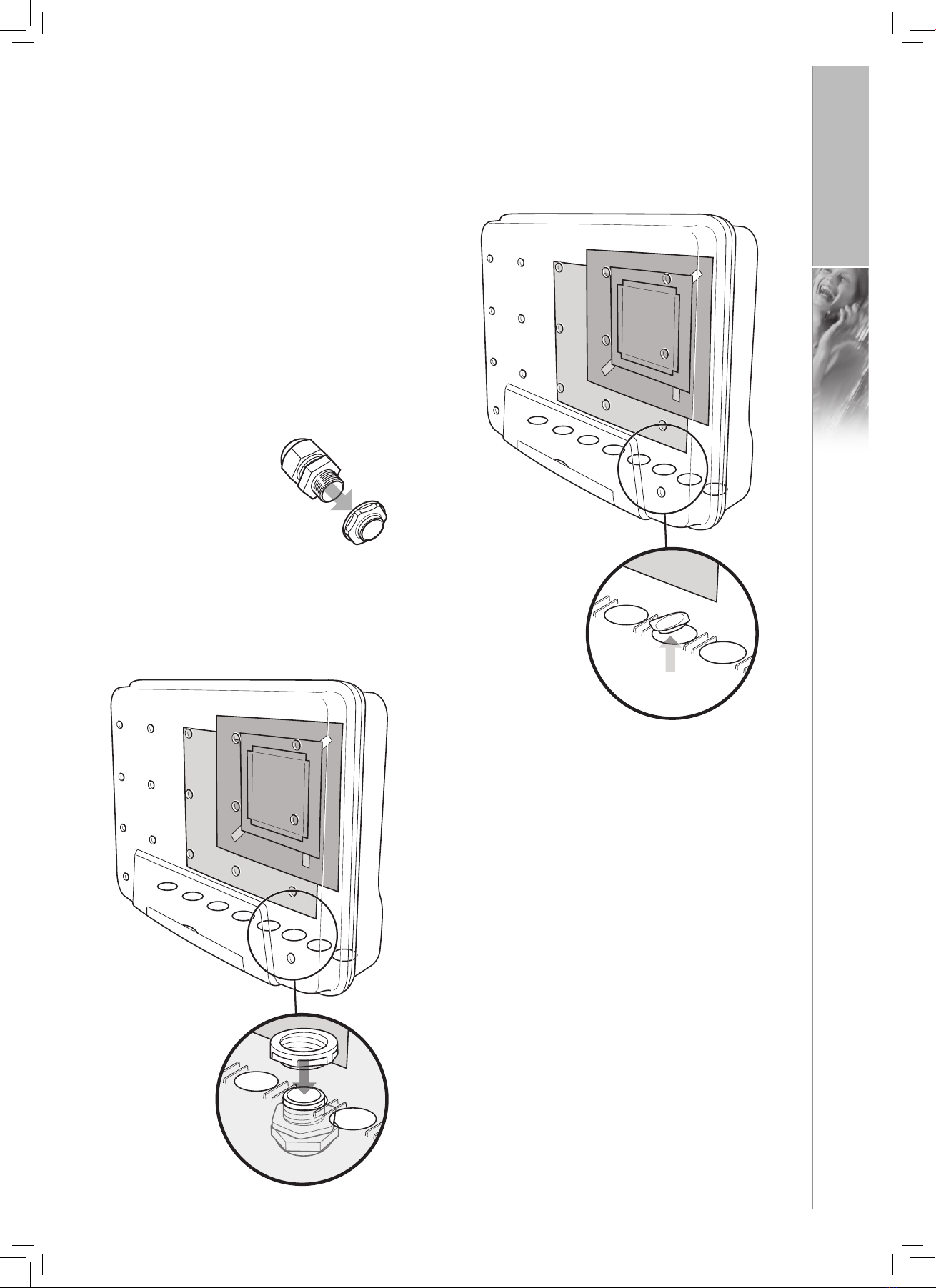
CONNECTING THE BASE STATION TO:
The Base Stations may be connected to either a (1) Sync Unit or a (2) Ethernet Sync/Switch Unit
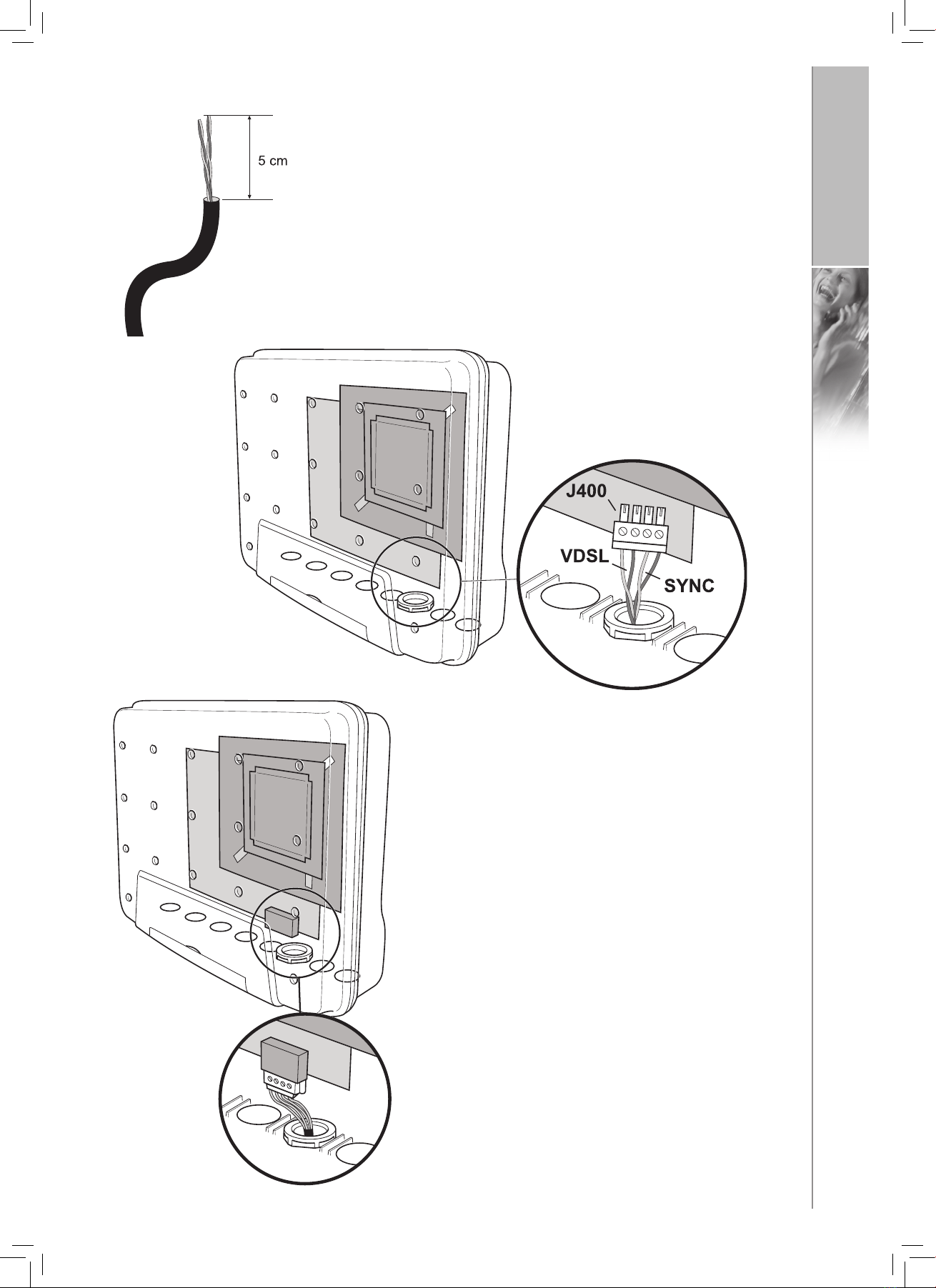
(1) Sync Unit
Connect at the 4-pin VDSL port (J400).
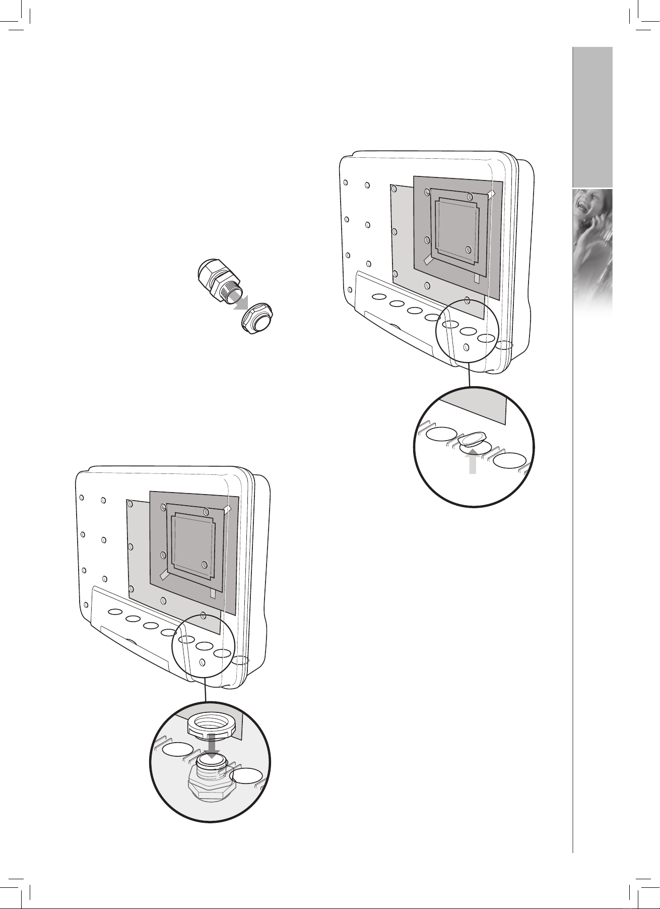
1) Punch out the plastic from a suitable hole in the housing.
2)
Unscrew the nut from
the cable gland supplied.
3)
Mount the cable gland in the hole and tighten the nut.
FIG. 6:
FIG. 7:
FIG. 8:
English
8
4)
Strip off about 5cm of the cable sheath and cut the wire to length.
5)
Insert through the gland seal and align the wires according to the
diagram below and insert them in the 4-pin VDSL male connector
(J400). The left pair of wires is for VDSL, the right pair for SYNC.
6)
Connect to the VDSL port.
Now the installation to the IP network via the VDSL port
is finished.
FIG. 9:
FIG. 10:
FIG. 11:
English
9
(2) Ethernet Sync/Switch Unit
Connect to a Ethernet Sync/Switch Unit using a 100Base-T straight through Ethernet cable – type CAT.5 – (both
ends are the same).
1)
Punch out the plastic from a suitable hole in the housing.
2)
Unscrew the nut from
the cable gland supplied.
3) Mount the cable gland in the hole and tighten the
nut.
FIG. 12:
FIG. 13:
FIG. 14:
English
10
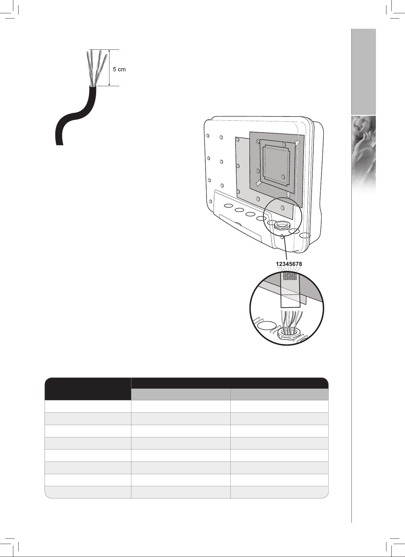
4) Strip off about 5cm of the cable sheath and cut the wires to length.
5) Insert through the gland seal and align the wires as in
Fig. 16 and Table 1 and insert into RJ-45 connector.
TABLE 1 – RJ-45 MDI Interface Pin Allocation
FIG. 16:
FIG. 15:
PIN NO. 100BASE-TX
SIGNAL FUNCTION
1 Tx+ Ethernet Transmit
2 Tx- Ethernet Transmit
3 Rx+ Ethernet Receive
4 DNIC-LINE B Synchronisation/GND
5 DNIC-LINE A Synchronisation/GND
6 Rx- Ethernet Receive
7 Power -48VDC
8 Power -48VDC
Table of contents
Other RTX Accessories manuals


