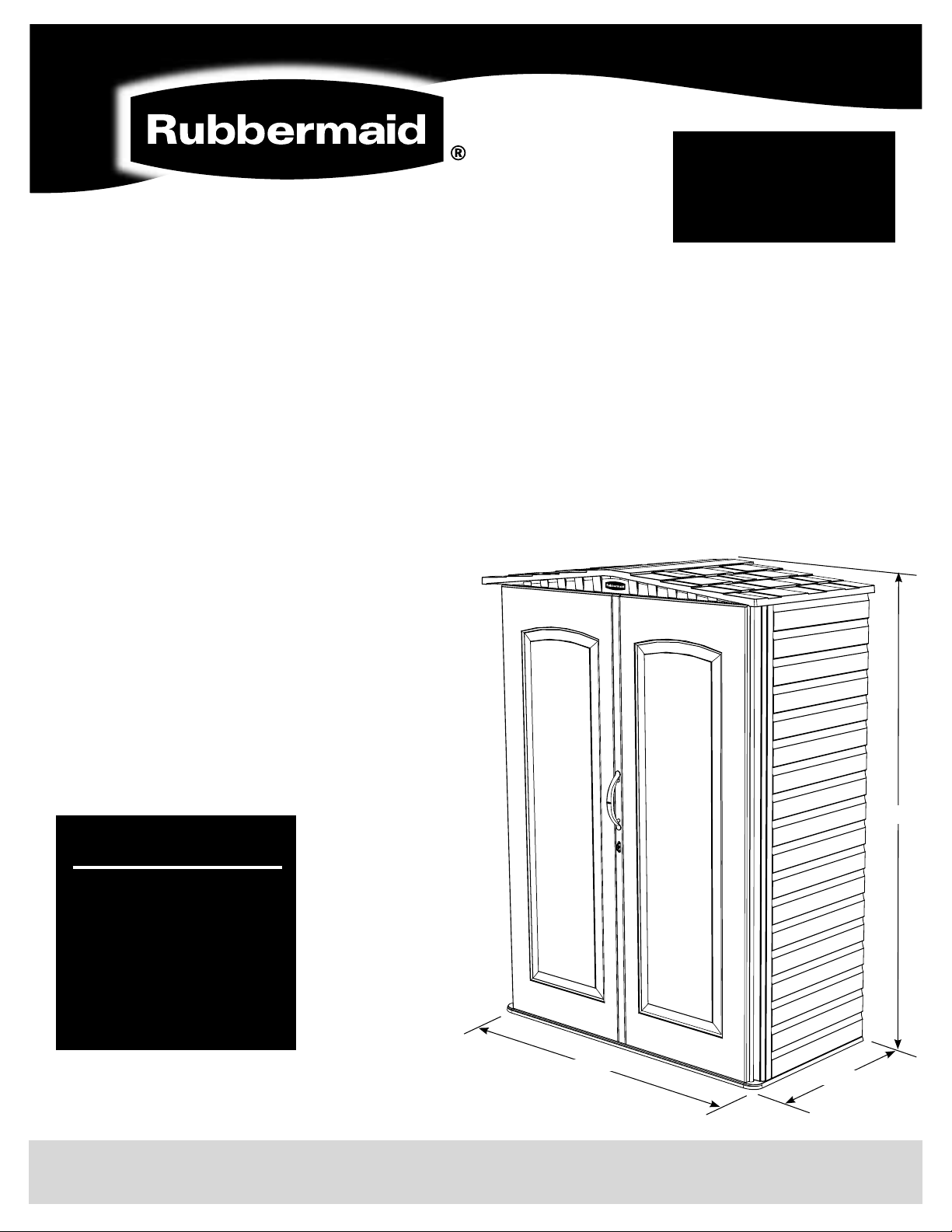
Congratulations and thank you for purchasing a Rubbermaid storage building.
BEFORE YOU BEGIN – BUILDING CODES
Be sure to check your local building codes, ordinances and restrictions, and applicable neighborhood governances.
BEFORE YOU BEGIN – SURFACE PREPARATION
To ensure proper assembly and performance your shed needs to be built on a solid, level surface.
A concrete or patio surface, or a treated-wood platform is recommended.
BEFORE YOU BEGIN – LOCATION
When choosing a location in your yard make sure you choose an area with easy access and one that provides
proper drainage for water to run away from the shed location.
BEFORE YOU BEGIN – PREASSEMBLY
Thoroughly review all assembly steps (it is important that
the steps are followed in the correct order). Review the
parts list and make sure that no parts are missing.
IMPORTANT – DO NOT RETURN TO THE STORE
For assistance with your Rubbermaid Storage Building
or for additional product information call our toll-free
Consumer Service number: 1-888-895-2110
M–F: 8:30 a.m. to 5:00 p.m. EST
or visit us online at: www.rubbermaid.com.
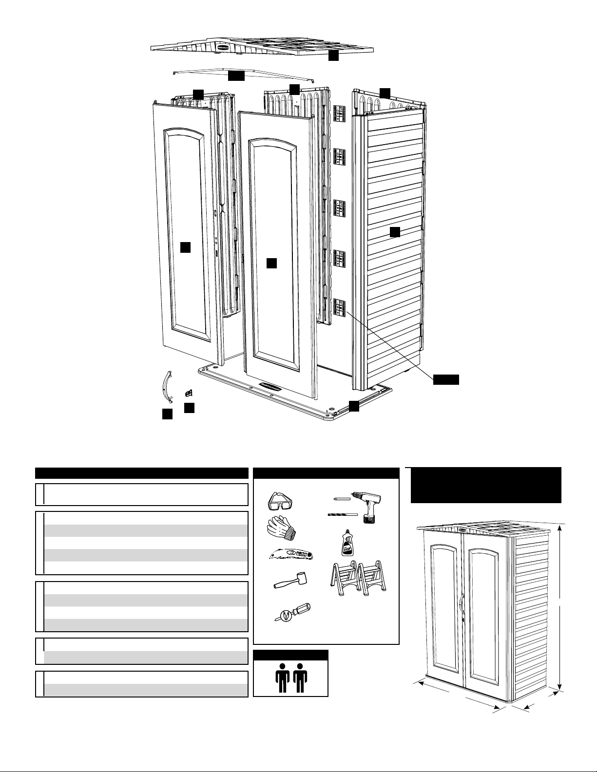
Installation Steps:
1. Site Preparation
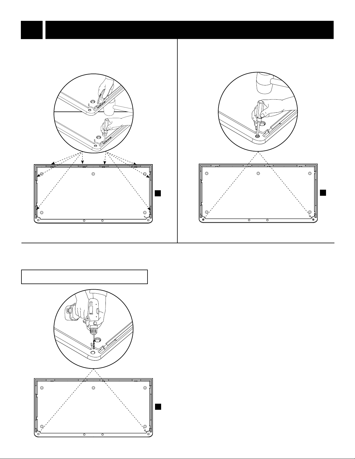
2. Floor
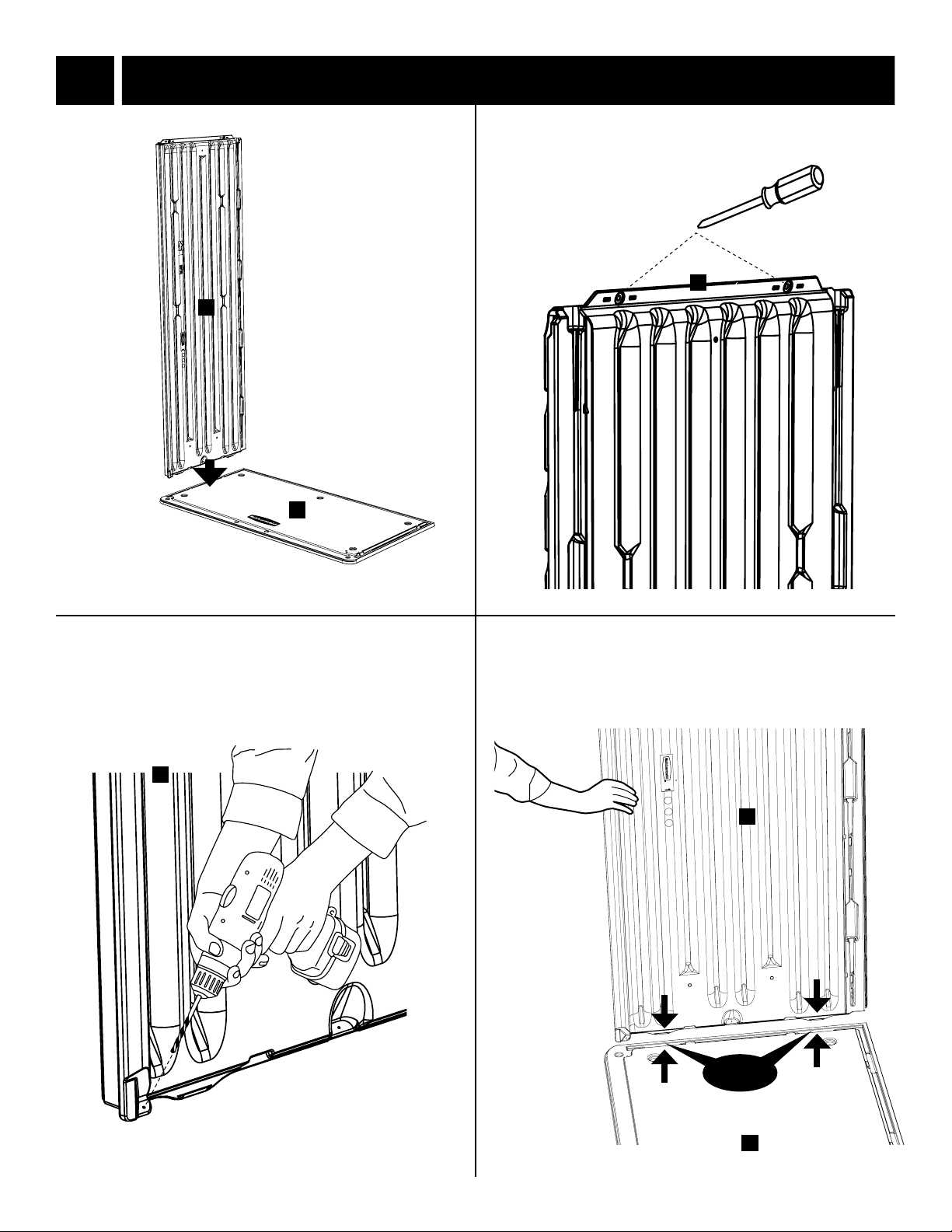
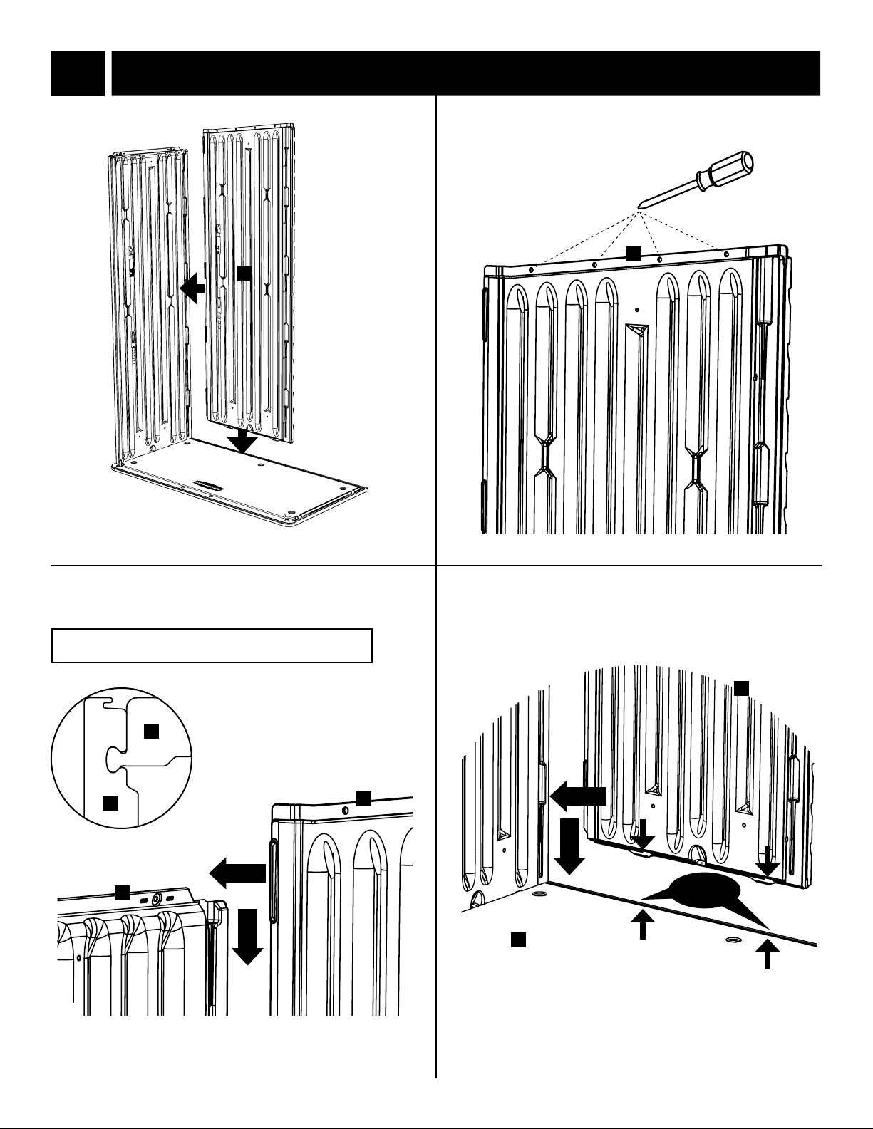
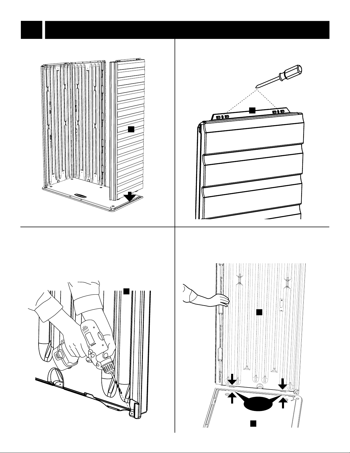
3. Walls
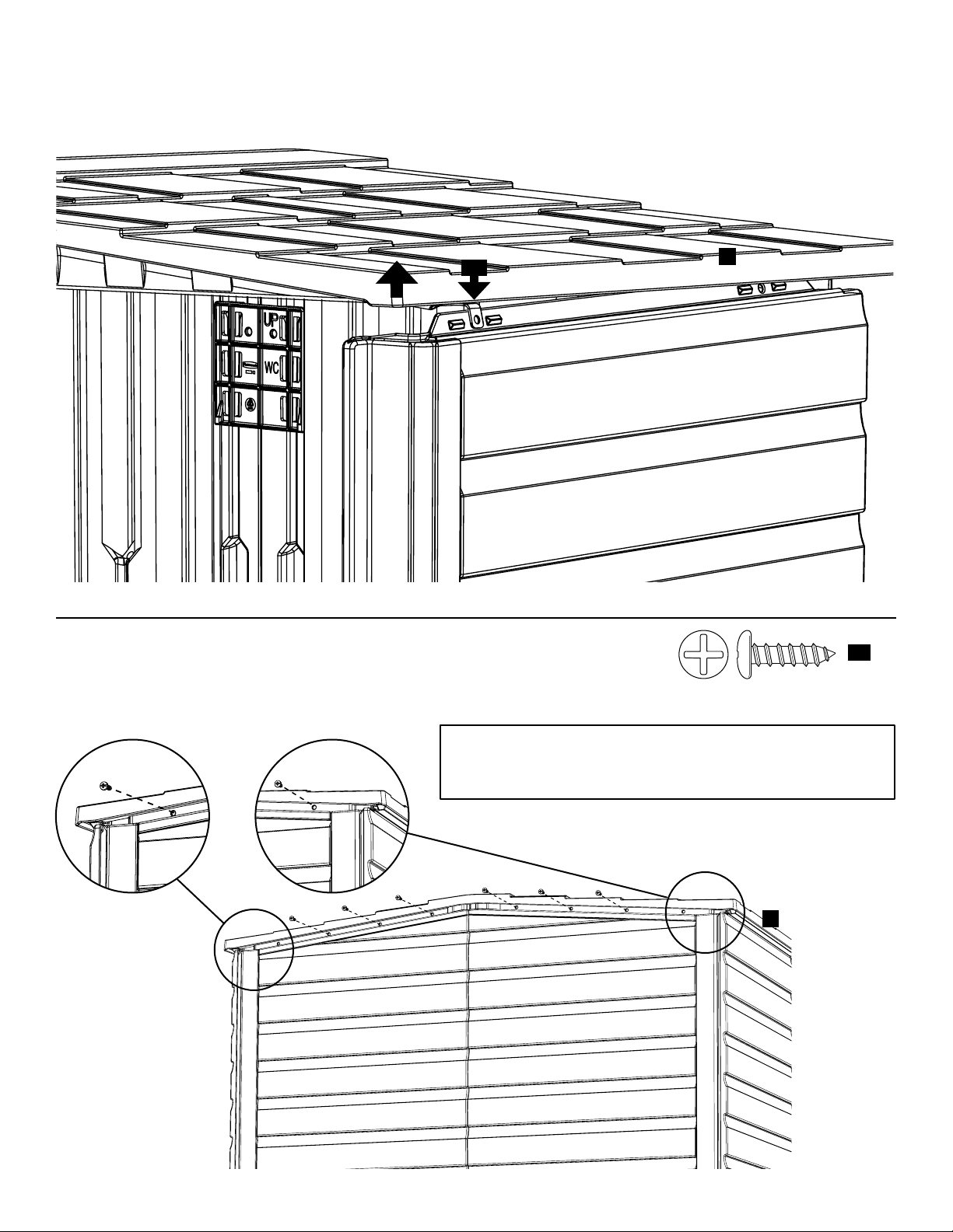
4. Roof & Doors
5. Finishing
5L10
7T53
76 ¾"
27 ½"
55 ¼"
2028019
Note: Be sure to keep this instruction manual and your original store receipt to ensure our Consumer Service
Department can accurately and quickly assist you if necessary.