Ruck Ventilatoren MPC D F4 T Series User manual

2018
MPC...D.F4 T
CONTENTS
Installation, operating and maintenance instructions
English
Example configuration shown
Smoke extract fan
for exhaust air
applications
ruck Ventilatoren GmbH
Max-Planck-Str. 5
D-97944 Boxberg-Windischbuch
Tel. +49 7930 9211-300
Fax +49 7930 9211-166
www.ruck.eu
e original instructions were created in the German language.
Information updated
print 22.07.2020
Subject to change
1. FOREWORD ............................................................................... 2
2. IMPORTANT INFORMATION .................................................................. 2
3. GENERAL SAFETY INSTRUCTIONS ............................................................. 3
4. ADHERE TO THE FOLLOWING INSTRUCTIONS ................................................... 6
5. PRODUCT INFORMATION .................................................................... 6
6. DELIVERY CONTENTS ....................................................................... 7
7. TECHNICAL DATA ........................................................................... 8
8. DIMENSIONS .............................................................................. 8
9. TRANSPORT AND STORAGE .................................................................. 9
10. ASSEMBLY ................................................................................ 9
11. ELECTRICAL CONNECTION .................................................................. 11
12. COMMISSIONING .......................................................................... 13
13. MAINTENANCE AND CLEANING .............................................................. 14
14. LIFETIME AND DISPOSAL ................................................................... 15
15. TROUBLESHOOTING ....................................................................... 16
www.ruck.eu
Made in EU

2| MPC...D.F4 T
EN
Installation, operating and maintenance instructions
1. FOREWORD
2. IMPORTANT INFORMATION
Dear customers,
ank you for choosing our device.
Before operating the unit, please read carefully these installation, operating and maintenance instructions. If you have
any questions, please contact: (Contact details see page 1)
e data provided in these installation, operating and maintenance instructions are for the product description only. A
statement about a certain condition or a suitability for a certain application cannot be derived from our information.
e information does not release the user from his own assessments and examinations.
All rights reserved by the manufacturer, even in the event of industrial property rights.
Any disposal such as copying and distribution rights lies with us.
is manual contains important information on the safe and appropriate assembly, transport, commissioning, operation,
maintenance, disassembly and simple troubleshooting of the product.
e product has been manufactured according to the accepted rules of current technology.
ere is, however, still a danger of personal injury or damage to equipment if the following general safety instructions and
the warnings before the steps contained in these instructions are not complied with.
■Read these instructions completely and thoroughly before working with the product.
■Keep these instructions in a location where they are accessible to all users at all times.
■Always include the operating instructions when you pass the product on to third parties.
2.1. Applicable Documents
e following documents and information on the exhaust fan must be observed in addition to the installation, ope-
rating and maintenance instructions:
Other applicable standards:
■DIN VDE 0100-100
■DIN EN 60204-1
■DIN EN ISO 13857
■DIN EN ISO 12100
■DIN EN 12101-3
■VDMA 24186-1
Available documents at www.ruck.eu
■Installation, operating and maintenance instructions
■Programming instruction FU (three-phase version)
■EC Declarations of conformity
■EC-Declaration of Incorporation (Directive 2006/42/
EC)
■Declaration of performance (Reg. 305/2011)
■Commissioning report
■Call to Tender
■Dimensioned drawing
■Technical drawing DWG
■Technical drawing DXF
■3D STEP
■Smoke extract certificate
Nameplate

3
EN
2.3. Warranty and liability
Our devices are manufactured to the highest technical level in accordance with the generally accepted rules of techno-
logy. ey are subject to constant quality controls. Because the products are being constantly developed, we reserve
the right to make changes to the products at any time and without prior announcement. We assume no liability for the
correctness or completeness of these installation, operating and maintenance instructions.
To ensure your warranty claims, it is imperative to provide a commissioning report and a maintenance record.
Warranty and liability claims for personal injury and property damage are excluded if they are due to one or more of
the following causes:
■Improper use
■Improper mounting, commissioning, operation and maintenance
■Operating the device with defective and / or non-functional safety and protective devices
■Failure to observe the instructions regarding transportation, installation, operation and maintenance
■Unauthorized structural changes to the device
■Poor monitoring and replacement of maintenance parts
■Improperly performed repairs
■Disasters and force majeure
3. GENERAL SAFETY INSTRUCTIONS
Planners, plant engineers and operators are responsible for ensuring that the product is installed and operated correc-
tly.
■Use our devices only in perfect technical condition.
■Check the device for obvious defects, such as cracks in the housing or missing rivets, screws, caps or other applica-
tion-relevant defects.
■Only use the device in the power range specified in the technical data and on the nameplate.
■Protection against contact and being sucked in and safety distances should be provided in accordance with DIN EN
13857.
■Generally prescribed electrical and mechanical protection devices are to be provided by the client.
■Safety components must not be bypassed or put out of operation.
■e product may be operated by personnel with limited physical, sensory or mental capacities only if they are su-
pervised or have been instructed by responsible personnel.
■Children must be kept away from the product.
2.2. Provisions and regulations
When properly installed and operated, the device complies with the applicable standards and EU Directive at the
time of its placing on the market.
In addition, observe generally valid, legal and other binding regulations of the European or national legislation as well
as the regulations in your country for accident prevention and environmental protection.
www.ruck.eu |

4| MPC...D.F4 T
EN
Installation, operating and maintenance instructions
3.2. Improper use
Any use of the product other than described in chapter “Intended use” is considered as improper.
e following points are improper and dangerous:
■Delivery of explosive and flammable media or operation in potentially explosive atmospheres.
■Delivery of aggressive and abrasive media.
■Operation without the duct system.
■Operation with closed air connections.
■e use on vehicles, aircrafts and ships.
3.3. Personnel qualifications
Assembly, commissioning, operation, disassembly and service (including maintenance and repair) require basic mecha-
nical and electrical knowledge, as well as knowledge of the appropriate technical terms. In order to ensure operating
safety, these activities may therefore only be carried out by qualified technical personnel or a person under the direc-
tion and supervision of qualified personnel. Qualified personnel are those who can recognize possible hazards and
institute the appropriate safety measures due to their professional training, knowledge, and experience, as well as
their understanding of the relevant conditions pertaining to the work to be done. Qualified personnel must observe the
rules relevant to the subject area.
In this manual, there are safety instructions before the steps whenever there is a danger of personal injury or damage
to the equipment. e measures described to avoid these hazards must be observed.
Safety instructions are set out as follows:
Safety sign (warning triangle) - Draws attention to the risk.
• Type of risk! - Identifies the type or source of the hazard.
»Consequences - Describes what occurs when the safety instructions are not complied with.
→ Precautions - States how the hazard can be avoided.
3.4. Safety instructions in this manual
3.1. Intended use
Our devices are incomplete machineries as defined in the EU Machinery Directive 2006/42/EC (partly completed ma-
chinery). e product is a not ready-for-use machine in terms of the machine directive.
It is intended exclusively for installation in a machine or in ventilation equipment and installations or for combination
with other components to form a machinery or installation. e product may be commissioned only if it is integrated
in the machinery/system for which it is designed and the machinery/system fully complies with the EC machinery di-
rective.
Observe the operating conditions and performance limits specified in the technical data.
Conveying and ambient temperatures must be observed according to the technical data and the nameplate.
Intended use also implies that you have fully read and understood this manual.
Improper use may result in danger to the life and limb of the user or third parties or damage to the system
or other property.

5
!
!
!
!
!
!
!
!
!
!
!
EN
General warning!
Indicates possible hazardous situations. Failure to observe the warnings may result in perso-
nal injury and / or damage to property.
Electricity warning (hazardous voltage)!
Indicates possible hazards due to electricity. Failure to observe the warnings may result in
death, injury and/or damage to property.
Hot surface warning!
Indicates possible hazards due to high surface temperatures. Failure to observe the warnings
may result in personal injury and/or damage to property.
Finger-Crushing Warning!
Indicates possible hazards due to moving and rotating parts. Failure to observe the warnings
may result in personal injury.
Overhead load warning!
Indicates possible hazards due to overhead loads. Failure to observe the warnings may result
in death, injury and/or damage to property.
Follow important information!
Instructions for safe, optimum use of the product.
Safety sign (warning
triangle)
Consequence
• Electricity warning (hazardous voltage)!
»Failure to observe the hazard may result in death,
injury or damage to property.
→ Before performing any work on conductive parts, al-
ways disconnect the unit completely from the electri-
city supply and make sure that it cannot be switched
back on again.
• Never reach into the impeller or other rotating or
moving parts.
»Failure to observe the hazard may lead to serious
injury.
→ Work may only be performed once the impeller has
come to a complete halt.
• Never clean the internal space with flowing water
or a high-pressure cleaner. Do not use aggressive or
easily flammable products for cleaning (impellers/
housing).
→
Only use mild soapsuds. e impeller should be cleaned
with a cloth or brush.
• General warning
»Failure to observe the warnings may result in personal
injury and / or damage to property.
→ Unauthorized repairs may cause personal injury and /
or damage to property, in which case the manufactu-
rer‘s guarantee or warranty will not apply.
• Caution! Burning hazard.
»Failure to observe the hazard may result in personal
injury and/or damage to property.
→ Do not touch the surface until the motor and heater
have cooled.
• Never reach into the impeller or other rotating or
moving parts.
»Failure to observe the hazard may lead to serious
injury.
→ Work may only be performed once the impeller has
come to a complete halt.
www.ruck.eu |

6| MPC...D.F4 T
EN
Installation, operating and maintenance instructions
5. PRODUCT INFORMATION
4. ADHERE TO THE FOLLOWING INSTRUCTIONS
4.1. General instructions
■Persons who assemble, operate, disassemble or maintain our devices must not be under the influence of alcohol,
drugs or pharmaceuticals that may affect perception and responsiveness.
■Responsibilities for the operation, maintenance and regulation of the product should be clearly determined and
observed so that there can be no unclear areas of responsibility with regard to safety.
4.2. Indications assembly
■Disconnect all of the product‘s poles from the mains before installing the product or connecting or removing plugs.
Make sure that the product cannot be switched back on again.
■Lay cables and lines so that they cannot be damaged and no one can trip over them.
■Information signs must not be changed or removed.
4.3. Indications Commissioning
■Make sure that all electrical connections are either used or covered. Commission the product only if it is installed
completely.
■e power switch must always be fully functional and easy accessible!
■Only authorized personnel is allowed to operate the setting mechanisms of the components or parts, under the
provision that the system is used as intended.
■In an emergency, or if there is a fault, or other irregularities, switch the equipment off and make sure it cannot be
switched back on again.
■e technical data given on the rating plate must not be exceeded.
4.4. Indications during operation
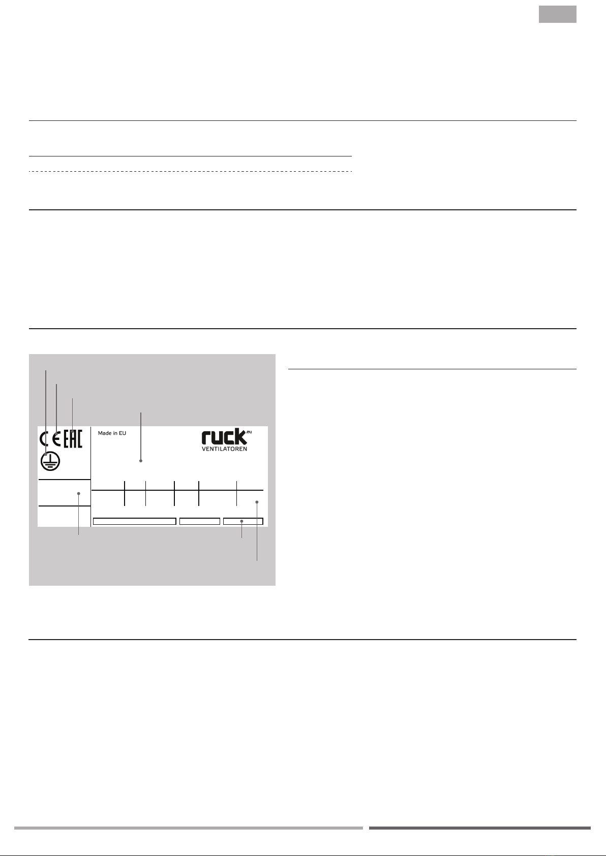
Description:
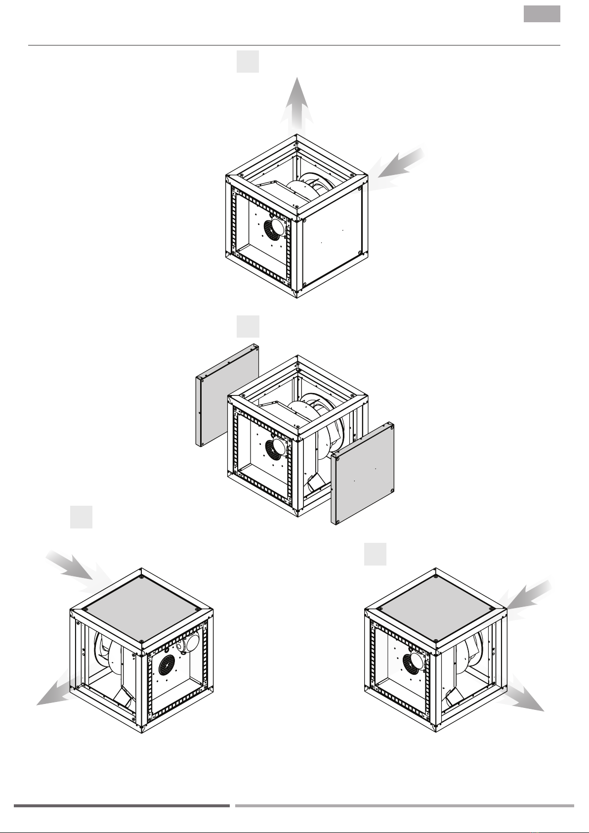
■Smoke extract fan for exhaust air applications
■is exhaust box with smoke extraction function can reliably deliver up to 400°C hot combustion gases in case
of fire for 2 hours. e exhaust air box must be replaced after a fire incident. Recurring operation at 400 °C is not
allowed.
■Conveyed exthaust up to 200 °C
■Radial impeller
■With condensate drain
■Motor outside the air stream (VDI 2052))
■Motor protection on site
■Tested according to EN 12101-3
■e back curved high-performance impeller consists of powder-coated sheet steel and is mounted on the shaft of
a standard three-phase motor. Impeller dynamically balanced in 2 planes according to quality standard G 6.3, DIN
ISO 1940. e ball-bearings are maintenance-free and lifetime lubricated. e motor is located outside the airflow.
■e built-in 3-phase motor with IE-3 classification can only be controlled by means of a frequency converter!
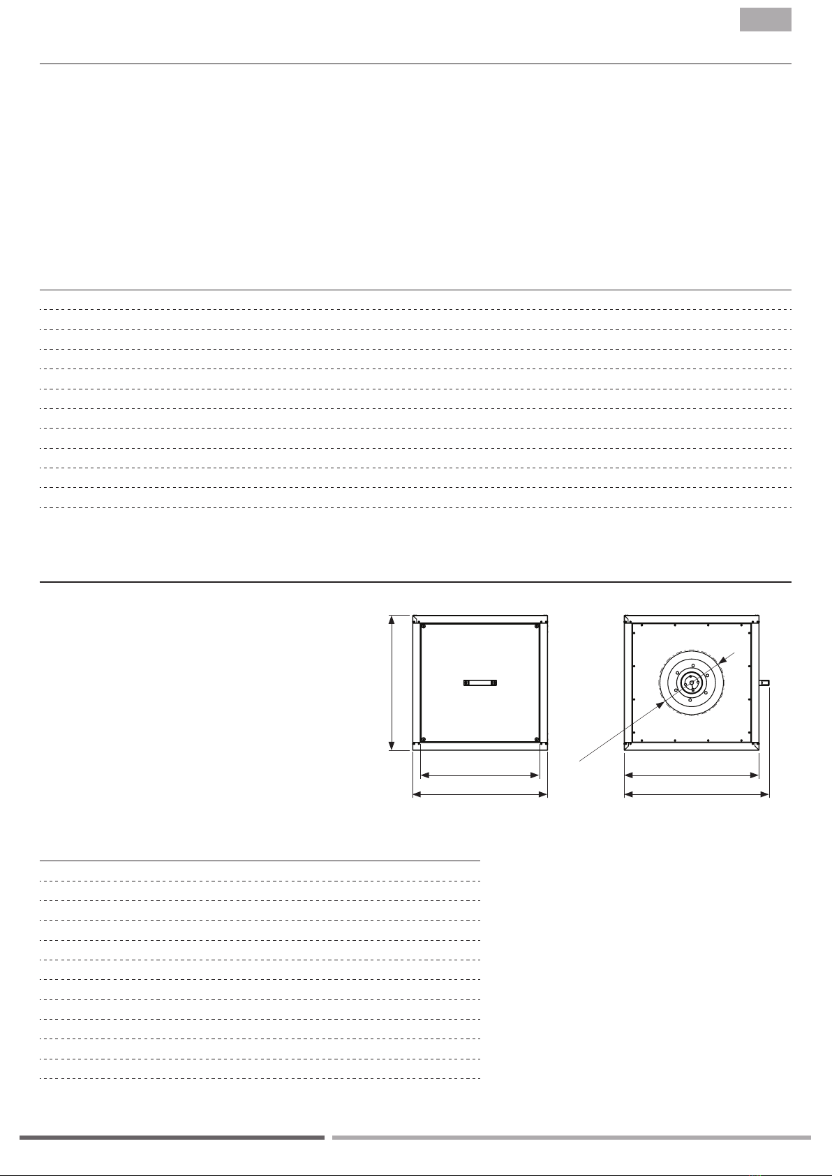
■Double wall cubic housing made of galvanized sheet steel with 30 mm thick mineral wool insulation, non-flammab-
le according to DIN EN 13501-1, class A1. Device bottom with integrated base pan and condensate drain.
For cleaning and maintenance work, the full-surface inspection door can be removed using the door handle. e door
handle is included loose and can be mounted on the desired side. e side walls as well as the cover can be easily remo-

7
EN
Series
perm. temperature / time
in smoke extraction
perm. temperature in
continuous operation
■MPC...T +400°C / 120 min -20°C bis +200°C
Legend:
■Imax Max. current consumption
■tA / tMMax. ambient temperature / Max. medium temperature
■P1N Rated power consumption
■nNRated speed
■ErP Data ErP Conformity, if required according to Reg. 327/2011
■η Overall efficiency
■N Efficiency at the optimum energy efficiency
■ID Item number
■SN Serial number
5.3. Nameplate
ATTENTION! e information on the nameplate must always be observed!
ErP 2015
Product name
Test date
CE marking
Protection class
5.1. Permissible conveying medium temperatures
5.2. Certification
e testing and factory certification required by EN 12101-3:2015 was carried out at the Slovenian National Building
and Civil Engineering Institute (ZAG).
Certificate Number: 1404-CPR-3071
To find under: www.zag.si/en/certificates
6. DELIVERY CONTENTS
■1 x Exhaust fan
■1 x Installation, operating and maintenance instructions
■EC Declarations of conformity
■EC-Declaration of Incorporation (Directive 2006/42/EC)
ved, thereby three different discharge directions are possible (left, right or up). e interior of the housing is completely
smooth without protruding screws. e side walls are screwed into the housing frame, so that no screws protrude into
the housing interior. Variable design of the discharge, this can be carried out on site by placing the inlet spigot based
on the choice of the air flow direction.
Insulation class motor
EAC marking
www.ruck.eu |
MPC 315 D2 F4 T30
06.11.2019
ID 146 446
SN 191106-Q00000-123
400V 3~Y
I
max.
t
A
/t
M
P1N
nN
50Hz
2,4A
60/200°C
1208W
2860 1/min
ISO F
VSD not integrated
N= 71
η=61,4% (A,static)
ErP 2015

8
D C
E
B
A
F
A B C D E F
mm mm mm mm mm mm
| MPC...D.F4 T
MPC...D.F4 T30
146426 500 500 500 417 552 min. 195
146434 500 500 500 417 552 min. 220
146443 500 500 500 417 552 min. 240
146446 500 500 500 417 552 min. 270
146453 500 500 500 417 552 min. 270
146465 700 700 700 617 752 min. 300
146472 700 700 700 617 752 min. 340
146474 700 700 700 617 752 min. 385
146476 700 700 700 617 752 min. 430
146478 900 900 900 817 952 min. 465
146481 900 900 900 817 952 min. 520
MPC 225 D2 F4 T30 146426 400V 3~Y 50 440 0,9 60 200 73 80 83 146221 35,0
MPC 250 D2 F4 T30 146434 400V 3~Y 50 692 1,2 60 200 73 82 84 146221 35,0
MPC 280 D2 F4 T30 146443 400V 3~Y 50 686 1,3 60 200 73 82 85 146221 36,0
MPC 315 D2 F4 T30 146446 400V 3~Y 50 1208 2,5 60 200 75 85 88 146221 44,4
MPC 315 D4 F4 T30 146453 400V 3~Y 50 221 1,1 60 200 68 78 81 146221 40,0
MPC 355 D4 F4 T30 146465 400V 3~Y 50 338 1,4 60 200 76 79 84 146221 63,0
MPC 400 D4 F4 T30 146472 400V 3~Y 50 564 1,1 60 200 69 74 76 146221 65,0
MPC 450 D4 F4 T30 146474 400V 3~Y 50 967 2,5 60 200 73 82 85 146221 73,0
MPC 500 D4 F4 T30 146476 400V 3~Y 50 1440 2,9 60 200 77 86 86 146221 75,0
MPC 560 D4 F4 T30 146478 400V 3~Y 50 2661 5,0 60 200 76 85 88 146221 127,0
MPC 630 D4 F4 T30 146481 400V 3~Y 50 4325 8,8 60 200 79 89 92 146221 140,0
EN
Installation, operating and maintenance instructions
Product name
Item number
Voltage UN
Frequency fN
Rated power consumption PN
Max. motor current Imax
Max. ambient temperature tA
Max. medium temperature tM
Sound power casing
Sound power inlet
Sound power outlet
Wiring diagram
Weight
VHz W A °C °C dB(A) dB(A) dB(A) kg
7. TECHNICAL DATA
8. DIMENSIONS
F
Artikelnummer

9
EN
9. TRANSPORT AND STORAGE
Transport and storage should only be performed by specialist personnel in accordance with the assembly and opera-
ting manual and regulations in force.
e following points should be noted and followed:
■Check the delivery according to the delivery note to ensure it is complete and correct and check for any damage.
Any missing quantities or damage incurred during transport should be confirmed by the carrier. No liability is accep-
ted if this is not observed.
■For weight see technical data
■It should be transported with suitable lifting equipment in the original packaging or on the transport equipment
indicated.
■If transported with a forklift, it should be ensured that the product is resting with the basic profile or base frame
completely on the forks or on a pallet and the product‘s centre of gravity is between the forks.
■e driver must be authorized to drive a forklift.
■Do not go beneath the suspended load.
■Avoid damage or deformation of the housing.
■e product must be stored in a dry area and protected from the weather in the original packaging. Open pallets
should be covered with tarpaulins. Even weatherproof modules should be covered because their weather resistan-
ce is only guaranteed after complete installation. If moisture has penetrated into the original packaging, remove it
immediately.
■Storage temperature between +5 °C and +40 °C. Avoid severe temperature fluctuations.
■If the product has been in storage for more than a year, check the smooth running of impellers and valves by hand.
10. ASSEMBLY
Assembly work may only be performed by specialist personnel in accordance with the installation and operating ma-
nual and the regulations and standards in force.
e following points should be noted and followed:
■e foundation must be even and levelled. It must not exhibit unevenness or a slope in any direction.
■Set up and align the machine with the aid of a water level. A perfect function of the device can be guaranteed only
if levelled mounted.
■Only suitable installation aids, in accordance with regulations, should be used.
■e device must be installed in such a way that it is easily accessible for maintenance and cleaning purposes.
■e unit should only be installed with authorized and suitable fastening materials at all fastening points.
■Do not distort the unit when installing.
■Just use the indicated mounting and fixing places. No holes should be made in the housing or any screws screwed
into it.
■e duct system must not be supported on the housing.
■For structure-borne sound decoupling, a flexible connection is recommended when connected on a duct system.
www.ruck.eu |

10
A
B
C
- kg
A3
Do not scale drawing
Protection Mark according to ISO16016
- mm
mm
General tolerances DIN ISO 2768-mK
1:10
ruck Ventilatoren
Max-Planck-Str. 5
D-97944 Boxberg
Rohling_MPC280D4T30
Intern
D
- kg
A3
Do not scale drawing
Protection Mark according to ISO16016
- mm
mm
General tolerances DIN ISO 2768-mK
1:10
ruck Ventilatoren
Max-Planck-Str. 5
D-97944 Boxberg
Rohling_MPC280D4T30
Intern
- kg
A3
Do not scale drawing
Protection Mark according to ISO16016
- mm
mm
General tolerances DIN ISO 2768-mK
1:10
ruck Ventilatoren
Max-Planck-Str. 5
D-97944 Boxberg
Rohling_MPC280D4T30
Intern
- kg
A3
Do not scale drawing
Protection Mark according to ISO16016
- mm
mm
General tolerances DIN ISO 2768-mK
1:10
ruck Ventilatoren
Max-Planck-Str. 5
D-97944 Boxberg
Rohling_MPC280D4T30
Intern
| MPC...D.F4 T
EN
Installation, operating and maintenance instructions
10.1. Mounting position
Delivery status
Discharge up
In order to change the discharge side, the panels or a panel
must be removed.
Inlet
Discharge
Discharge
Inlet
Inlet
Discharge
By closing an open side, the discharge side can be changed.
Discharge left
Discharge right

11
EN
e electrical installation may only be carried out by qualified electricians in compliance with the installation, operating
and maintenance instructions and the applicable national regulations, standards and guidelines:
■ISO, DIN, EN and VDE specifications, including all safety requirements.
■Technical connection conditions.
■Safety at work and accident prevention requirements.
is list does not claim to be complete.
Requirements should be applied under one‘s own personal responsibility.
■e electrical connections must be made as shown in the corresponding wiring diagrams and terminal diagrams.
■e type of cable, size of cable and method of laying should be determined by an authorized electrician.
■Low and extra-low voltage cables should be laid separately.
■If no repair switch is integrated in the device, an all-pole mains disconnecting switch with min. 3 mm contact
opening must be provided in the supply line.
■Use a separate cable inlet for each cable.
■Any cable inlets that are not used must be sealed so that it is airtight.
■All cable inlets must have strain relief.
■Create equipotential bonding between the unit and the duct system.
■Check all protective measures after the electrical connection work (earthing resistance, etc.)
■Motor current and motor power must not exceed the values stated on the motor nameplate. e specified max.
fan speed must never be exceeded, otherwise the motor and fan will be destroyed by this overload and dissolved
or flying parts can destroy other components.
11. ELECTRICAL CONNECTION
• Electricity warning (hazardous voltage)!
»Failure to observe the hazard may result in death, injury or damage to property.
→ Before performing any work on conductive parts, always disconnect the unit completely from the electri-
city supply and make sure that it cannot be switched back on again.
Connect the mains supply cable as shown in the wiring diagram. For the dimensioning of the line, observe the unit‘s
rating plate and the relevant guidelines. Appropriate protection with correctly dimensioned automatic safety breakers
(circuit protection breaker) must be provided.
e device must be connected according to the wiring diagram. For fans which are controlled by external control de-
vices, the corresponding operating instructions of the manufacturer must be observed.
11.1. Unit supply cable / Electrical connection / wiring diagram
www.ruck.eu |

12
0.245 kg
A4
Do not scale drawing
Protection Mark according to ISO16016
mm
mm
General tolerances DIN ISO 2768-mK
1:2
ruck Ventilatoren
Max-Planck-Str. 5
D-97944 Boxberg
Daniel Andree
12.10.2017
Klemmkasten_extern
Intern
0.245 kg
A4
Do not scale drawing
Protection Mark according to ISO16016
mm
mm
General tolerances DIN ISO 2768-mK
1:2
ruck Ventilatoren
Max-Planck-Str. 5
D-97944 Boxberg
Daniel Andree
12.10.2017
Klemmkasten_extern
Intern
0.001 kg
Material <nicht festgelegt>
A4
Do not scale drawing
Protection Mark according to ISO16016
mm
mm
General tolerances DIN ISO 2768-mK
2:1
ruck Ventilatoren
Max-Planck-Str. 5
D-97944 Boxberg
Daniel Andree
12.10.2017
140777
Intern
0.001 kg
Material <nicht festgelegt>
A4
Do not scale drawing
Protection Mark according to ISO16016
mm
mm
General tolerances DIN ISO 2768-mK
2:1
ruck Ventilatoren
Max-Planck-Str. 5
D-97944 Boxberg
Daniel Andree
12.10.2017
140777
Intern
| MPC...D.F4 T
EN
Installation, operating and maintenance instructions
If, in spite of the correct connection to the mains or to the frequency converter, the devices turn con-
trary to the given direction of rotation, this must be corrected. For this purpose two phases can be
interchanged at the terminal block (e.g. L1 with L2 or L2 with L3). Afterwards the direction of rotation
is to be checked again.
For the electrical connection, for the setting of the motor protection switch or for the parameterization
of a frequency inverter, only the technical data on the nameplate of the fan are relevant. ese may
differ from the technical data of the motor.
■Star circuit
■Delta circuit
For the star circuit, the terminals U2, V2 and W2 are
connected through the shorting blades (see Img.).
Never connect both jumpers at the same time!
For the delta circuit, the shorting blades are connecting
U1 with W2, V1 with U2 and W1 with V2 (see Img.).
Never connect both jumpers at the same time!
11.2. Star circuit / Delta circuit
e star circuit must be used if the motor is to be ope-
rated directly on the 3-phase supply network with a
line voltage of 400V.
e star circuit is also to be used when controlling via a
frequency inverter with 400V output voltage (usually a
frequency converter with 3-phase 400V mains connec-
tion).
e delta circuit must be used if the motor is to be ope-
rated directly on the 3-phase supply network with a
line voltage of 230V.
e delta circuit is also to be used when controlling
via a frequency inverter with 230V output voltage (in
general frequency converter with 1-phase 230V mains
connection).
During operation, electric motors heat up. Under certain circumstances (excessively high ambient or fluid temperatu-
res, heavy contamination, etc.), the motor temperature may exceed the safety limit of the electrically isolated parts.
In order to avoid engine damage, various types of temperature monitoring are possible, of which at least one must be
installed on site:
■Monitoring of the thermal motor current via a FU
■Motor protection switch
11.3. ermal motor protection
e following connections are only possible for sizes 225 ... 560:

13
MPC 225 D2 F4 T30 146426 50 60 1,1 1,9
MPC 250 D2 F4 T30 146434 50 60 1,4 2,4
MPC 280 D2 F4 T30 146443 50 50 1,5 2,6
MPC 315 D2 F4 T30 146446 50 50 2,7 4,7
MPC 315 D4 F4 T30 146453 50 80 1,3 2,3
MPC 355 D4 F4 T30 146465 50 70 1,6 2,8
MPC 400 D4 F4 T30 146472 50 50 1,3 2,3
MPC 450 D4 F4 T30 146474 50 55 2,7 4,7
MPC 500 D4 F4 T30 146476 50 50 3,1 5,4
MPC 560 D4 F4 T30 146478 50 50 5,2 9
MPC 630 D4 F4 T30 146481 50 50 9 15,6
EN
If third-party products are used, the following parameters must be set correctly.
e use of a fault current protection switch is not mandatory. If a fault current protection switch is used, only AC/DC
sensitive RCD protective devices (type B or B+) are permitted.
Product name Item number Rated frequency
fN
Maximum frequency
fmax
Max. motor current Imax
3~400V Y
Max. motor current Imax
3~230V D
Hz Hz A A
11.5. Fault current protection switch
Even when the device is switched off, voltage is applied to terminals and connections. Do not touch the
device for 5 minutes after all-pole disconnection from the mains.
If the fans are placed on the EU market or operated within the EU, they must have a speed control. is is only possible
by means of frequency converters. Using other speed controls, such as voltage control, will directly damage the motor.
We offer tested and approved frequency converters as accessories. ese are pre-programmed and delivered exactly
matched to the respective engine power and speed.
11.4. Frequency converter
12. COMMISSIONING
Commissioning by trained technical personnel may only be performed after any risk has been ruled out. e
following checks should be performed in accordance with the installation and operating manual and the re-
gulations in force:
■Correctly sealed installation of the unit and duct system.
■Check the duct system, unit and medium lines, if present, remove any foreign bodies if necessary.
■e intake opening and inflow into the unit must be clear.
■Check all mechanical and electrical protection measures (e.g. earthing).
■Voltage, frequency and type of current must correspond with the rating plate.
Note:
Standard frequency inverters have a modified sine-wave at the output. is may cause noises, depending on the com-
bination motor - frequency converter. Depending on the fan design and the radiating surface, these are perceptible.
At very high noise requirements, this can be disturbing. For industrial applications, the noises are generally acceptable.
Remedial measures may be a change in the clock frequency or the use of a sine-wave filter or a frequency converter
with integrated sine-wave filter.
www.ruck.eu |

14 | MPC...D.F4 T
EN
Installation, operating and maintenance instructions
Servicing, troubleshooting and cleaning may only be performed by specialised personnel in accordance
with this installation and operating manual and the regulations in force.
■Make sure that no connections or components are loosened unless the device is disconnected from the
mains. Make sure that the equipment cannot be switched back on again.
■Individual components must not be interchanged. For example, the components intended for one pro-
duct may not be used for other products.
■e regular maintenance and care of our devices is designed to ensure proper function, value retention
and avoidance of damage. Keep a maintenance log.
■Perform the specified maintenance on the unit at the specified intervals.
13. MAINTENANCE AND CLEANING
Our devices require little maintenance when operated properly.
e following work should be performed at regular intervals, in accordance with health and safety regulations:
■Check the operation of the control system and safety devices.
■Check electrical connections and wiring for damage.
■Remove any dirt from the fan impeller or impellers and from inside the fan housing in order to prevent any unba-
lance or reduction in output.
– Do not use aggressive or easily flammable products for cleaning (impellers/housing).
–
Preferably only water (not flowing water) or mild soapsuds should be used.
– e impeller should be cleaned with a cloth or brush.
– Never use a high-pressure cleaner.
– Balancing clips must not be moved or removed.
– e impeller and fittings must not be damaged in any way.
Before putting the unit back into operation after maintenance and servicing work, carry out a visual inspection as de-
scribed in section 11 and 12.
13.1. Checklist Maintenance and Service
Description check interval
Triggering device monthly
■Fan
Check fan for function and operational readiness (test run at least 15 minutes) every 6 months
Check fan for function and operational readiness (test run at least 1 hour) yearly
Check for dirt, damage, corrosion and fastening every 6 months
Function-preserving cleaning every 6 months
Check impeller rotation direction yearly
Check flexible connections for leaks yearly
Check impeller for imbalance yearly
Check protective device for function yearly
■Motor
Check externally for dirt, damage, corrosion and fastening every 6 months
Function-preserving cleaning yearly
Check bearing for noise yearly
Check terminals for tight fit yearly
Measure the voltage yearly

15
A
A
B
B
A-A
B-B
1
2
3
3
4
EN
14. LIFETIME AND DISPOSAL
14.1. Product life
e motors are equipped with maintenance-free, permanently lubricated ball bearings. Under normal operating condi-
tions, the expected lifetime is about 30,000 operating hours.
e information given here depends strongly on the respective field of application as well as the environmental condi-
tions. We recommend replacing these fans after reaching about 30,000 operating hours or 5 years.
13.2. Impeller installation with Taperlock clamping bush
1.Clean all bare surfaces (mating surfaces of
the clamping bushings and motor shaft).
2.Insert the clamping bush (1) into the hub (2)
and bring the holes into alignment.
3.Loosely lubricate the threaded pins (3) and
screw in - do not tighten yet.
4.Push the impeller onto the shaft with the
clamping sleeve, align it in the axial position
and tighten the threaded pins evenly on both
sides. Observe the tightening torque accor-
ding to table.
Assembly
e impeller is connected by means of the clamping bush to the shaft end of the drive motor.
Disassembly
1.Loosen all the threaded studs (3) and screw
them out completely. Lubricate a threaded
pin and screw it into the disassembly hole
(4).
2.Tighten the threaded pin until the clamping
bush (1) is released from the hub (2).
3.e impeller can be removed.
Bushing size
Torque table
Bushing size 1210 2012 2517
Screw tightening torque with feather
(Nm) 17 26 41
Screw tightening torque without feather
(Nm) 20 31 48
Number of screws 2 2 2
Technical data
Commissioning (after replacement)
■Remove any remaining installation material and foreign objects from the impeller and suction area.
■Check direction of rotation (direction of rotation arrow on the impeller base disc).
■During initial commissioning, the entire unit must be checked for mechanical vibrations. If necessary, re-balancing
must be carried out.
■Pay attention to a quiet operation, without vibrations.
www.ruck.eu |

16 | MPC...D.F4 T
EN
Installation, operating and maintenance instructions
14.2. Decommissioning and disposal
When disassembling, parts under voltage are exposed, which can lead to electric shock when touched.
Before dismantling, disconnect the fan from all poles of the mains and secure against being switched on
again!
14.3. Spare parts (motor + impeller)
Only original spare parts may be used.
e repair may only be carried out by personnel trained and authorized.
Parts and components of the device that have reached their lifetime, e.g. due to wear, corrosion, mechanical stress,
fatigue and/or all other, not directly recognizable effects, must be disposed of professionally and properly after disas-
sembly in accordance with national and international laws and regulations. e same applies to excipients in use such
as oils and fats or other substances. e conscious or unconscious reuse of used components such as e.g. impellers,
rolling bearings, motors. etc. can lead to a risk to persons, the environment as well as machinery and equipment. e
applicable local operating regulations must be observed and applied.
Fault Possible cause Remedy methods
■Fan does not start ■No power supply ■Check mains supply / connections
■Impeller does not rotate freely ■Find out the causes and, if possible, remove
the fault. If not possible, contact the sup-
plier.
■Motor overheated
/ temperature
protection is tig-
gered
■Fault of the ball bearings ■Contact the supplier
■Too high operating temperature ■Observe the data on the nameplate
■Air flow is too low, motor cannot cool
down
■See fault „Low air flow“
■Device too noisy /
casing vibrations
■Dirt deposits on the impeller ■See chapter maintenance and cleaning
■Imbalance of the impeller ■Contact the supplier
■Connection with intake or exhaust pipe /
duct causes vibrations / oscillations
■Install fan with vibration dampers
■Fixing screws released ■Tighten screws
■Fault of the ball bearings ■Contact the supplier
■Loose impeller blade ■Contact the supplier
■Low airflow ■Impeller runs in the wrong direction (wrong
air transport direction)
■Note the marking on the device / nameplate.
Check electrical connections
■High pressure losses in the system ■Improve piping configuration or select a
more powerful fan
■Return flaps closed or only partially open ■Check drive system / installation position of
the return flap
■Duct system clogged ■Remove blockage / clean protective grille
■Speed control incorrectly set / incorrectly
connected
■Check settings / switching unit and possibly
adjust / connect
15. TROUBLESHOOTING

Information updated
print 22.07.2020
mpctg_pb_06_en
We reserve the right to make changes
Language:
English
ruck Ventilatoren GmbH
Max-Planck-Str. 5
D-97944 Boxberg-Windischbuch
Tel. +49 7930 9211-300
Fax +49 7930 9211-166
www.ruck.eu
This manual suits for next models
22
Table of contents
Popular Scrubber manuals by other brands

Windsor
Windsor STRIDE 2 operating instructions

PowerPoint
PowerPoint P2161XBIN Directions for installation, use and maintenance

Tennant
Tennant Nobles 3301 Use and care guide

Sana
Sana EUJ-702 user manual

DiamaPro Systems
DiamaPro Systems DP-SCRUB20 owner's manual

Black & Decker
Black & Decker Scrub brusher 9385 owner's manual

Tacony
Tacony Powr-Flite PFX1080AW Operators manual and parts lists

PowerBoss
PowerBoss Nautilus user manual

Clarke
Clarke ENCORE MAX Operator's manual & parts list

HAKO
HAKO Scrubmaster B400 R operating manual

Nilfisk-Advance
Nilfisk-Advance ecoflex BA 511D user manual

Weller
Weller Zero Smog EL Translation of the original instructions