ICE-BALANCER
User Instructions - Part 2
1. Safety Instructions
Please take into consideration extreme circumstances or
shock loads when choosing components.
The ICE-Balancer must not be used under load with an
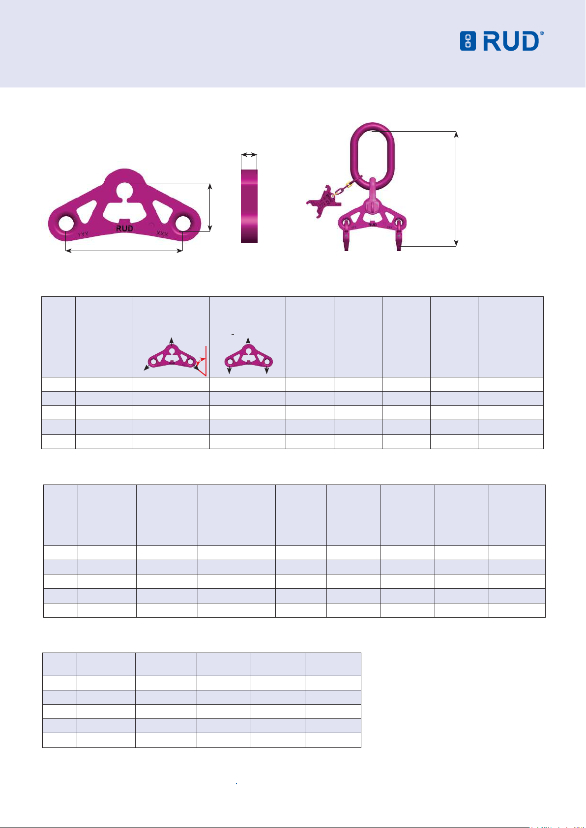
inclination angle of greater than 10° (see pic 11).
The inclination angle ß must not exceed 45° (90° internal
sling angle) refer pic 13 and 14.
ICE-Balancers must only be used by designated and trained
persons by observing the BGR 500 requirements, chapter 2.8,
and outside Germany acc. to the country specic regulations.
For Australia, please refer to AS 3775.2.
2. Intended Use
ICE-Balancers are installed into 4-leg sling assemblies (2
x 2-leg), to achieve an equal load distribution to all 4 legs
(pic 17). The length tolerances of the single legs will be
compensated by the disposition of the ICE-Balancer.
Please ensure that the ICE-Balancer does not exceed the
limit inclination angle of 10° (pic 11). By the special shape of
the ICE-Balancers you can easily realise the limit inclination
angle of 10°.
During use ensure that the 2-leg sling with the balancer is not
used separately.
Observe the safety instructions: “Lifting means used for lifting
of loads must especially avoid that loads shift unattended or
drop in free fall.”
ICE-Balancers must only be used in the conditions stated in
this instruction.
You can calculate with 4 load bearing strands if the following
criteria are followed (BGR500):
• Two 2-leg slings, one sling with a balancer.
• Both 2-leg slings attached to one hook (single or double
crane hook)
• Symmetrical load spreading/sharing
• Max. inclination angle ß 45° (90° internal sling angle)
WARNING
The 2-leg sling with the balancer should not be used
seperatly as a 2-leg sling. Lifting means for lifting of
loads must avoid that loads can shift unintentionally.
3. Assembly and Instruction Manual
3.1 General Information
• Capability of temperature usage:
When used at temperatures higher than 200°C the working
load limits (WLL) of the ICE-Balancer must be reduced as
follows:
-60°C up to 200°C no reduction
200°C up to 250°C minus 10 %
250°C up to 300°C minus 40 %
Temperatures exceeding 300°C are prohibited!
• ICE-Balancer must not be used with aggressive chemicals
such as acids, alkaline solutions and their vapours.
• The balancer head consists of the following components:
• IAK-Master Link
• VV-SCH / VC-SCH
• ICE-Balancer
• IVS ICE-Connecting Link
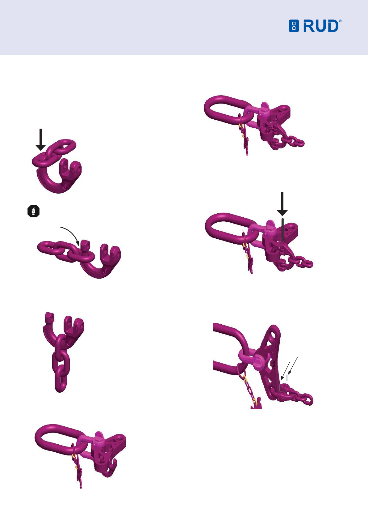
3.2 Assembly Instructions
3.2.1 Assembly of masterlinks and shackles
Please observe the correct sizing of masterlinks, shackles
and balancers during assembly and repairing (see table 2).
During the assembly of the balancer sling please proceed as
follows:
1. Align the components to be assembled (Pic 1).
2. Attach shackle bow into IAK-Master Link.
3. Move shackle bow and IAK Master link over the top hole of
the balancer plate.
4. Close shackle by placing the shackle pin through the
balancer plate connecting hole.
5. Turn shackle pin completely in and secure it always with a
cotter or a sleeve pin. The shackle must now be securely
connected to the balancer.
NOTE
The bow of the shackle must always be secured:
Cotter pin for VC-SCH 5.0 and VC-SCH 6.0
Sleeve pin for VV-SCH 10, 13 and 16
Pic 2: Assembled balancer
with shackle.
IAK-Master Link
Shackle Bow
ICE-Balancer
Shackle Pin
Pic 1: Component assembly.