RUD VRBS-FIX User manual

1VRBS
RUD Ketten
Rieger & Dietz GmbH u. Co. KG
73428 Aalen
Tel. +49 7361 504-1370
Fax +49 7361 504-1171
www.rud.com
RUD-Art.-Nr.: 8502954-EN V02 - 07.022
Lifting ring weldable
> VRBS <
Safety instructions
This safety instruction/declaration has to be kept on le for the
whole lifetime of the product and forwarded with the product.
TRANSLATION OF THE ORIGINAL INSTRUCTION
EG-Konformitätserklärung
entsprechend der EG-Maschinenrichtlinie 2006/42/EG, Anhang II A und ihren Änderungen
Hersteller:
RUD Ketten
Rieger & Dietz GmbH u. Co. KG
Friedensinsel
73432 Aalen
Hiermit erklären wir, dass die nachfolgend bezeichnete Maschine aufgrund ihrer Konzipie-
rung und Bauart, sowie in der von uns in Verkehr gebrachten Ausführung, den grundle-
genden Sicherheits- und Gesundheitsanforderungen der EG-Maschinenrichtlinie
2006/42/EG sowie den unten aufgeführten harmonisierten und nationalen Normen sowie
technischen Spezifikationen entspricht.
Bei einer nicht mit uns abgestimmten Änderung der Maschine verliert diese Erklärung ihre
Gültigkeit.
Produktbezeichnung: Ringbock
_____________________________________________
VRBS-FIX / VRBK-FIX / VRBG / VRBS / VRBK
_____________________________________________
Folgende harmonisierten Normen wurden angewandt:
DIN EN 1677-1 : 2009-03 DIN EN ISO 12100 : 2011-03
_________________ _________________
_________________ _________________
_________________ _________________
_________________ _________________
_________________ _________________
Folgende nationalen Normen und technische Spezifikationen wurden außerdem angewandt:
DGUV-R 109-017 : 2020-12
_________________ _________________
_________________ _________________
_________________ _________________
_________________ _________________
_________________ _________________
Für die Zusammenstellung der Konformitätsdokumentation bevollmächtigte Person:
Michael Betzler, RUD Ketten, 73432 Aalen
Aalen, den 15.04.2021 Hermann Kolb, Bereichsleitung MA
_____________________________________________
Name, Funktion und Unterschrift Verantwortlicher
VRBS - Lifting ring weldable in pink
EC-Declaration of conformity
According to the EC-Machinery Directive 2006/42/EC, annex II A and amendments
Manufacturer: RUD Ketten
Rieger & Dietz GmbH u. Co. KG
Friedensinsel
73432 Aalen
We hereby declare that the equipment sold by us because of its design and construction,
as mentioned below, corresponds to the appropriate, basic requirements of safety and
health of the corresponding EC-Machinery Directive 2006/42/EC as well as to the below
mentioned harmonized and national norms as well as technical specifications.
In case of any modification of the equipment, not being agreed upon with us, this declara-
tion becomes invalid.
Product name: Load ring
_____________________________________________
VRBS-FIX / VRBK-FIX / VRBG / VRBS / VRBK
_____________________________________________
The following harmonized norms were applied:
DIN EN 1677-1 : 2009-03 DIN EN ISO 12100 : 2011-03
_________________ _________________
_________________ _________________
_________________ _________________
_________________ _________________
_________________ _________________
The following national norms and technical specifications were applied:
DGUV-R 109-017 : 2020-12
_________________ _________________
_________________ _________________
_________________ _________________
_________________ _________________
_________________ _________________
Authorized person for the configuration of the declaration documents:
Michael Betzler, RUD Ketten, 73432 Aalen
Aalen, den 15.04.2021 Hermann Kolb, Bereichsleitung MA
_____________________________________________
Name, function and signature of the responsible person
EN

2VRBS
Before initial usage of the RUD VRBS ple-
ase read carefully the safety instructions.
Make sure that you have understood all
subjected matters. Non-observance can
lead to serious personal injuries and mate-
rial damage and eliminates warranty.
1 Safety instructions
ATTENTION
Wrong assembled or damaged lifting points
as well as improper use can lead to injuries
of persons and damage of objects when
load drops.
Please inspect all lifting points before each
use.
• Remove all body parts (fingers, hands, arms,
etc.) out of the hazard area (danger of crushing or
squeezing) during the lifting process.
• Attention: When suspension ring pivots there is a
risk of pinching.
• RUD Lifting points VRBS must only be used by
instructed and competent persons considering
DGUV 109-017 and outside Germany noticing the
country specic statutory regulations.
• Do not exceed the working load limit (WLL) indica-
ted on the lifting point.
• No technical alterations must be implemented on
the VRBS.
• No people may stay in the danger zone.
• Detention under a oating load is forbidden.
• Jerky lifting (strong impacts) should be prevented.
• Always ensure a stable position of the load when
lifting. Swinging must be prevented.
• Damaged or worn VRBS must never be utilised.
2 Intended use of the VRBS
RUD Lifting points VRBS must only be used for the
assembly at the load or at lifting means. They are
designed and intented to attach lifting means.
RUD Lifting points can also be used as lashing points
to attach lashing means.
RUD lifting points must only be used for the hereby
described usage and operation purpose.
3 Assembly- and instruction manual
3.1 General information
• Capability of temperature usage:
As of 07/2019: RUD Lifting points VRBS are suitable
for the temperature range from -40°C up to 400°C.
Up to 07/2019: RUD Lifting points VRBS are sui-
table for the temperature range from -20°C up to
400°C.
For the use within the following temperature range,
the WLL must be reduced by the following factors:
-40°C/-20°C up to 200°C no reduction
200°C up to 300°C minus 10 %
300°C up to 400°C minus 25 %
Temperatures exceeding 400°C are prohibited!
In the unloaded state, VRBS lifting point together
with the load can be stress relieved by heat treating
(e.g. welded construction) once.
Temperature: < 600°C (one hour maximum).
• RUD lifting points VRBS must not be used with
aggressive chemicals such as acids, alkaline solu-
tions and their vapours.
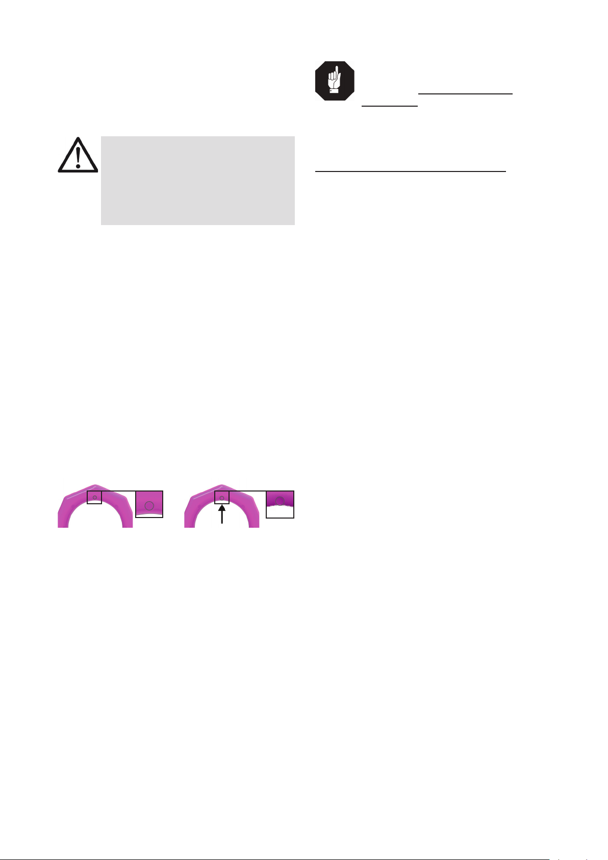
• Please mark mounting position of lifting point with
a coloured contrast paint for better visibility.
• VRBS will be delivered with a pink powder coated
lifting ring.
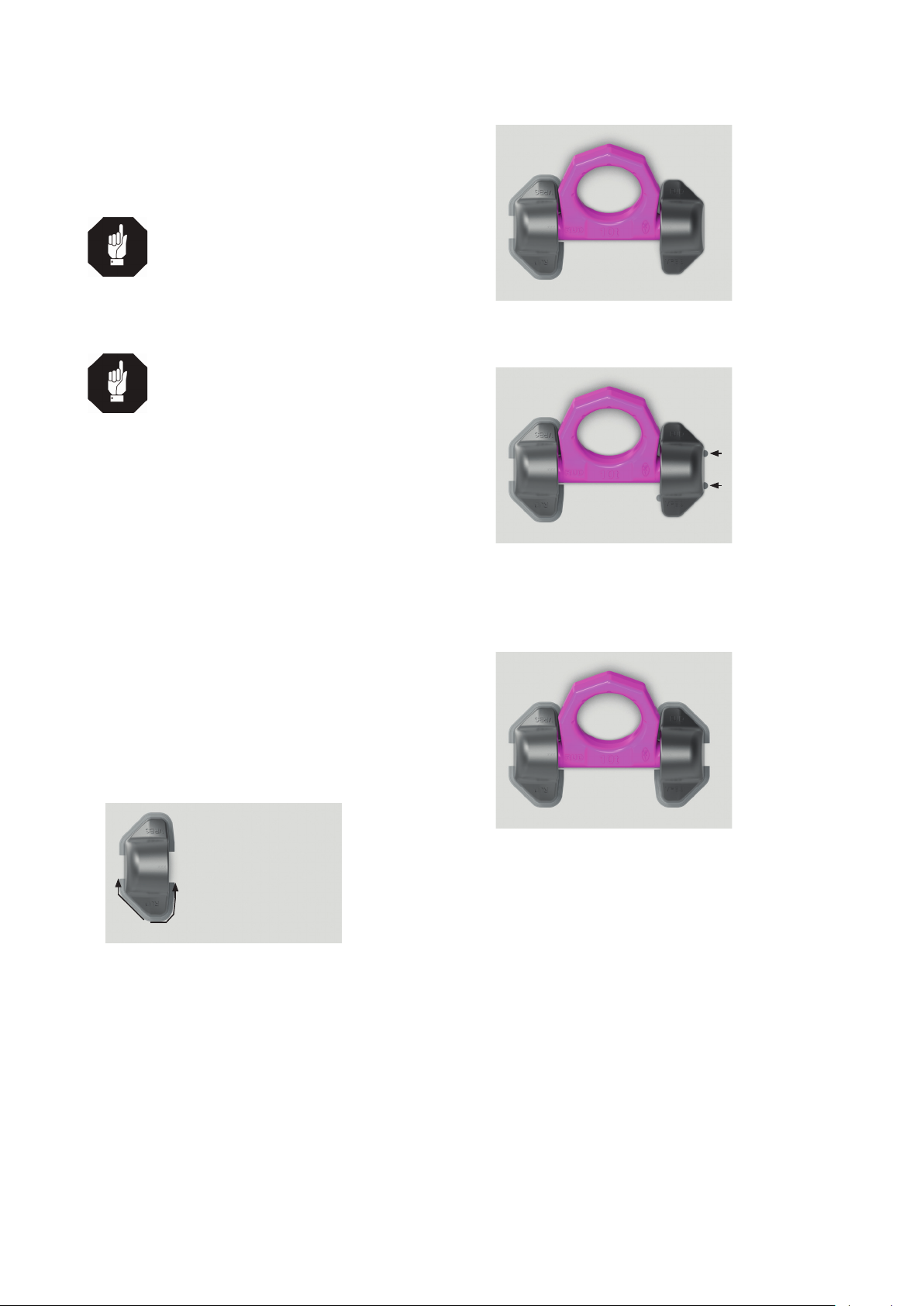
3.2 Hints for the assembly
Basically essential:
• The material construction to which the lifting
point will be attached should be of adequate
strength to withstand forces during lifting wit-
hout deformation. The weld-on material must
be suitable for welding and the contact are-
as must be free from dirt, oil, colour, ect.
The material of the forged welding block is
S355J2+N (1.0577+N (St52-3))
• The position of the lifting points must be carried
out in such a way that unintended movement like
turning or ipping will be avoided.
• For single leg lifts, the lifting point should be
vertically above the centre of gravity of the load.
• For two leg lifts, the lifting points must be
equidistant to/or above the centre of gravity
of the load.
• For three and four leg lifts, the lifting points
should be arranged symmetrical around the
centre of gravity, in the same plane if possible.
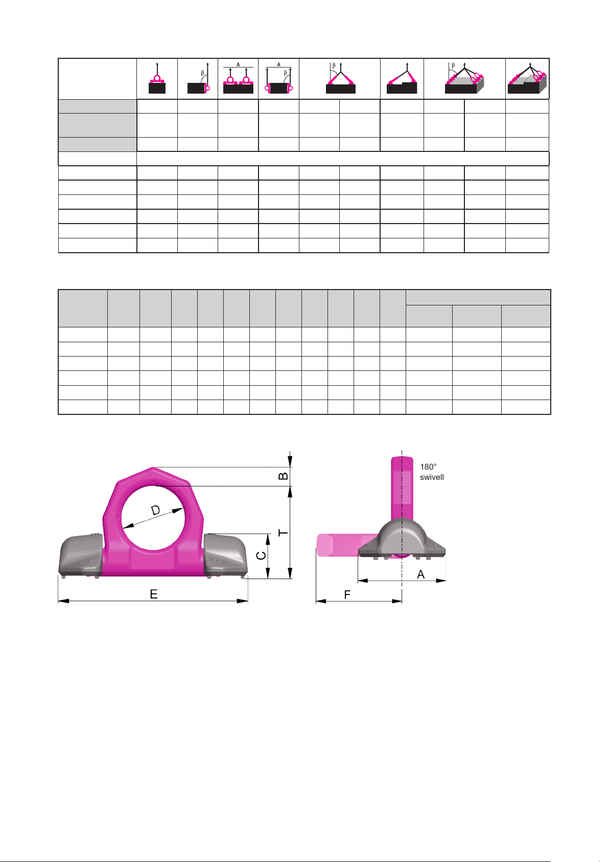
• Load symmetry:
Determine the necessary WLL of each lifting point
for a symmetrical load by using the following phy-
sical calculation formula:
WLL = necessary WLL of lifting point /
single strand (kg)
G = weight of load (kg)
n = number of load bearing strands
ß = inclination angle of single strand
WLL=G
n x cos ß
Number of load bearing strands:
Symmetric Unsymmetric
two leg 2 1
three / four leg 3 1
Table 1: Load bearing strands (compare to Table 4)
• Check nally the correct assembly (see chapter 4
Inspection / Repair / Disposal).

3VRBS
3.3 Hints for the welding
The welding should only be carried out according to
DIN EN ISO 9606-1 or AWS Standards by an autho-
rized and certied welder.
Verication of the used weld-on material must be
checked with the supplier of the welding electrodes.
HINT
The pre-heating temperature for the welding
of the VRBS 31,5 t and 50 t must be between
150°C and 170°C.
1. Weld on welding block 1.
HINTS
• The described welding sequences
must be observed compulsive.
• Weld all seams at the same tempe-
rature.
• Keep the area of gap for escape of
water clear.
• The distance lugs assist in achieving
the correct root weld (approx. 3 mm =
0.1 inch). They may not be removed.
• Never weld at the quentched and tem-
pered ring!
• Remove any welding mistakes and dirt
at the root weld before applying the
cover weld seams.
• Avoid end craters.
Begin at starting point S* and weld the root and
cover weld seams (Pic. 1).
Append llet weld (measurement „a“) acc. Table 2.
Choose type of weld seam and size according to
Pic. 6 and Table 2.
S*
Pic. 1: Weld on welding block 1
2. Insert the pink powder coated lifting ring into the
welded-on welding block 1.
3. Attach welding block 2 as tight as possible to the
ring, in order to still guarantee moveability of ring.
Pic. 2: Align ring and check mobility
4. Tack weld-on block 2 in the area of the distance
lugs (only fasten provisionally).
Pic. 3: Attachment in the area of the distance lugs.
5. Check function of the ring. The ring must be able
to pivot 180°. If necessary please correct.
6. Weld on the welding block 2 according to steps 1
and 2.
Pic. 4: Weld on welding block 2
7. Please check by a competent person after welding
the ongoing usage of the weld-on lifting point (see
chapter 4 Inspection / Repair / Disposal).

4VRBS
3.4 User instructions
• Check frequently and before each initial operation
the whole lifting point in regard of linger ability as
a lifting mean, regarding corrosion, wear, defor-
mation etc. (see chapter 4 Inspection / Repair /
Disposal).
ATTENTION
Wrong positioned or damaged weld-on
lifting points as well as improper use can
lead to injuries of persons and damage at
property, when load falls down.
Please check all lifting points carefully
before every usage.
• RUD components are designed according to DIN
EN 818 and DIN EN 1677 for a dynamic load of
20,000 load cycles.
• Keep in mind that several load cycles can occur
with a lifting procedure
• Keep in mind that, due to the high dynamic
stress with high numbers of load cycles, that
there is a danger that the product will be da-
maged.
• The BG/DGUV recommends: For higher dyna-
mic loading with a high number of load cycles
(continuous operation), the working load stress
must be reduced according to the driving me-
chanism group 1Bm (M3 in accordance with
DIN EN 818-7). Use a lifting point with a higher
working load limit.
• Please check carefully the wear indicator markings
of the weld-on lifting point (see picture 1):
Use prohibited:
Replacement criteria
reached. Material all the
way down to the wear
lenses has gone.
Usage permitted:
no wear marks
visible
Pic. 5: Wear indicators
• Please note that the lifting mean must be free mo-
veable within the weld-on lifting point VRBS. When
lifting means (sling chains) are hinged or unhinged,
no pinching, shearing or joint spots must occure
during the handling.
• Avoid damage of lifting means resulting from sharp
edges.
• If RUD VRBS lifting points are used solely for
lashing, the value of the working load limit can
be doubled. LC = permissible lashing force =
2 x working load limit (WLL)
HINT
If the VRBS is/was used as a lashing point,
with a force higher than the WLL, it must
not be used as a lifting point afterwards.
If the VRBS is/was used as a lashing point,
up to the WLL only, it can still be used af-
terwards as a lifting point.
4 Inspection / Repair / Disposal
4.1 Hints for the regularly inspection
The operator has to determine and dictate the neces-
sary inspection periods and the deadlines by a risk
assessment (see sections 4.2 and 4.3).
The persisting appropriateness of the lifting poinr
must be checked by a competent person (auditor) at
least once per year.
Depending on the conditions of use e.g. frequent
use, increased wear or corrosion, it may be neces-
sary to carry out inspections at shorter intervals
than once per year. A verication is also required
following damage and after special events.
The operator must specify the test cycles.
4.2 Inspection criteria for the regularly
examination carried out by the operator
• Completeness of the lifting point
• Complete, readable WLL statements as well as
manufacturer sign.
• Deformation on load bearing parts like base body
and ring.
• Mechanical damage, like strong notches, espe-
cially in areas where tensile stress occurs.
4.3 Additional inspection criteria for the
competent person resp. auditor
• Reduction of cross-section due to wear > 10 %
• Evidence of corrosion (pitting)
• Additional inspections may be necessary depen-
ding on the result of the risk assessment (e.g.
incipient cracks at load bearing parts).
4.4 Disposal
Dispose worn out components / attachments or
packaging according to the local waste removal
requirements.

5VRBS
weld
size length volume
VRBS 4 t HY 4 + a 3 2 x 130 mm ca. 4.5 cm³
VRBS 6,7 t HY 5.5 + a 3 2 x 170 mm ca. 9 cm³
VRBS 10 t HY 6 + a 4 2 x 190 mm ca. 11 cm³
VRBS 16 t HY 8.5 + a 4 2 x 250 mm ca. 26 cm³
VRBS 31.5 t HY 18 + a 4 2 x 365 mm ca. 88 cm³
VRBS 50 t HY 25 + a 8 2 x 655 mm ca. 450 cm³
Table 2: weld size (per welding block)
ca. 3 mm
(0.1 - 0.2 inch)
Z
HY
Table 3: Seam welding denition
Pic. 6: Schematic diagramm item „Z“ Welding
position PB
Ring Gap for escape of water
Welding blocks
Pic. 7: components VLBS
Pic. 8: Ring integrated in the construction:
distance lugs
approx. 3 mm (0.1 - 0.2 inch)
Pic. 9: distance lugs
Europe, USA, Asia, Australia, Africa
Baustähle, niedrig legierte Stähle EN 10025
Mild steels, low alloyed steel
MIG / MAG (135)
Gas shilded wire welding
(135)
DIN EN ISO 14341: G4Si1 (G3Si1)
Z.B. PEGO G4Si1
E-Hand Gleichstrom
(111, =)
Stick Electrode direct current
DIN EN ISO 2560-A: E 42 6 B 3 2 H10
DIN EN ISO 2560-A: E 38 2 B 1 2 H10
z.B. PEGO B Spezial*/ PEGO BR Spezial*
E-Hand
(Wechselstrom 111, ~)
Stick Electrode
alternating current
DIN EN ISO 2560-A: E 38 2 RB 1 2
DIN EN ISO 2560-A: E 42 0 RC 1 1
z.B. PEGO RC 3 / PEGO RR B 7
Alternativ:
DIN EN ISO 3581: E 23 12 2 L R 3 2
z.B. PEGO 309 MoL
WIG (141)
TIG Tungsten arc
welding
DIN EN ISO 636-A: W 3 Si 1 (W2 Si 1)
DIN EN ISO 636-A: W 2 Ni 2
z.B. PEGO WSG 2 / PEGO WSG2Ni2
HINT
Please note the
corresponding user
hint in regard of the
welding ller materials and the
drying requirements*.
The pre-heating temperature
for the welding of the VRBS
31,5 t und 50 t must be bet-
ween 150°C and 170°C.
Table 4: Welding procedure + Welding ller metals

6VRBS
Method of lift
G
G
G
G
G
G
G
G
Number of legs 1 1 2 2 2 2 2 3 / 4 3 / 4 3 / 4
Angle of
inclination <ß 0° 90° 0 ° 90° 0-45° >45-60° Un-
symm. 0-45° >45-60° Un-
symm.
Factor 1 1 2 2 1.4 1 1 2.1 1.5 1
Type For the max. total load weight >G< in metric tons
VRBS 4 t 4 t 4 t 8 t 8 t 5.6 t 4 t 4 t 8.4 t 6 t 4 t
VRBS 6.7 t 6.7 t 6.7 t 13.4 t 13.4 t 9.4 t 6.7 t 6.7 t 14.1 t 10 t 6.7 t
VRBS 10 t 10 t 10 t 20 t 20 t 14 t 10 t 10 t 21.2 t 15 t 10 t
VRBS 16 t 16 t 16 t 32 t 32 t 22.4 t 16 t 16 t 33.6 t 24 t 16 t
VRBS 31.5 t 31.5 t 31.5 t 63 t 63 t 45 t 31.5 t 31.5 t 67 t 47.5 t 31.5 t
VRBS 50 t 50 t 50 t 100 t 100 t 70 t 50 t 50 t 105 t 75 t 50 t
Table 5: WLL overview
Type WLL
[t]
weight
[kg/pc]
A
[mm]
B
[mm]
C
[mm]
D
[mm]
E
[mm]
F
[mm]
T
[mm]
O
[mm]
Q
[mm]
Ref-no
VRBS Ring Welding
block
VRBS 4 t 4 0,9 62 14 28 48 135 71 65 19+0,5 77+1 7992826 7906890 7992004
VRBS 6.7 t 6.7 2.1 88 20 39 60 170 92 84 25+0,5 101+1 7992827 7906891 7992005
VRBS 10 t 10 3.0 100 22 46 65 195 100 95 30+0,5 106+1 7992828 7906892 7992007
VRBS 16 t 16 6.9 130 30 57 90 263 134 127 38+0,5 147+2 7992491 7906893 7992008
VRBS 31.5 t 31.5 15.6 160 42 79 130 375 195 178 50+0,5 222+2 60267 7906894 7987160
VRBS 50 t 50 54 240 70 120 230 620 340 313 65+0,5 375+2 56834 7907412 7987161
Table 6: Dimensioning Subject to technical alterations
180°
swivelling
Pic. 10: Dimensioning
This manual suits for next models
4
Table of contents
Other RUD Lifting System manuals