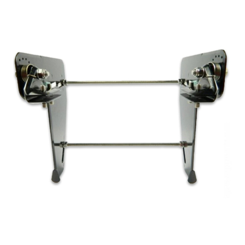
If you are to derive full satisfaction from Ruddersafe it is important to take great care with the tting. Check
the contents of the box with the parts list (Figure 2). Study the“X-ray” picture (page 1) to make sure you
understand how the parts are to be tted together.
Fitting the brackets.
Fitting the rudderblades
1. Screw the set screws (C) into the brackets, but do
not screw them through the plate. Make sure that
the screws engage properly in the slanted threaded
holes. The latter should be lubricated with grease.
2. The spiral springs (F) are left-handed and right-
handed. Spring marked in green is for R-H rudder
blade, and red for L-H. Position the springs over the
rudderblade bearing with the colour-marked leg
of the spring in the rearmost adjustment hole (see
arrow marking).
4. Tighten the bolt with a wrench and lock it by rmly
tightening the shallow lock-nut to be put on the end
of the bolt (see arrow).
6. Screw the track-bolt (E) about 3-4 turns into the
half-brackets. The rudder is now ready for insertion
on to the cavitation plate.
5. Bolt (D) with plastic sleeve is tted to the rudder
blade through hole No.2 (see g. 2). Fix the other bolt
(D) at the topo of hole No.3. When using an engine
with a steep propeller pitch, it may be necessary to
place the top bolt in hole No.1.
8. Lift the bracket up so that the cross-stay is close
up against the underside of the cavitation plate.
Press the rudder right up against the cavitationplate.
Bring the half-brackets towards eachother with the
track-bolt (E), but no more than sucient to keep
the distance between the two half-brackets equal at
the top and bottom (see arrow 1).
10. Place the ller shims (G) on the cavitation plate
(see arrow) and screw the set-screws (C) tight with
the hex wrench supplied. Do not tighten the set
screws to tightly.
12. If the rudder blades are not parallel, adjust the
nuts on one side. Tighten the nuts and check-
tighten the other connections. Check that the
rudder can be moved up and down normally, and
that the propeller rotates freely.
In order to eliminate over-steer (heavy on the helm), Ruddersafe is designed so that the rudder gradually lifts itself
out of the water and planes at the same time as the boat. The sprins (F) are to prevent the rudder from lifting too
soon. Test run the rudder with the springs in the middle adjustment hole. If necessary, move the spring legs until the
boat regains directional stability.
Ruddersafe is made of corrosion-resistant materials and treated with heat-cured epoxy. For use in sea water all parts
should be primed with anti-fouling. Rub the rudder down with sandpaper before applying anti-fouling.
After 5-10 hours running, all nut an bolt connections on the rudder should be tightened.
11. The distance between the rudder blades must be
the same at all points shown. Maximum tolerance 1
mm. If the gap is greater than this, i.e. if the blades
are not parallel, then the rudder may move up and
down sluggishly.
7. Bring the rudder in towards the cavitation plate
until the top bolt (D) is up against the cavitation
plate. Engage the top cross-stay (B) in the grooves in
the bracket.
9. Make sure that the bracket is at right-angles to
the cavitation plate. The clearance between the
propeller and eacht rudder blade must be minimal
40mm. The clearance is adjusted by moving the top
bolt (D) along the groove or by moving the bracket
longitudi-nally. The lock-nut that has to be tted on
the end of the track-bolt (E) must be tightened hard.
Check once more if the bracket is at right-angles to
the cavitation plate.
3. Insert bolt (A) into the rudderblade with the
washer at the end, so that the bolt projects approx
5- 6 mm on the inside of the rudderblade. Fit the
appropriate half-bracket to the spring, the bevelled
edge turned towards the leg of the spring (see arrow
1), so that the leg of the spring is at the front of the
bracket (see arrow 2).
Screw the bolt (A) into the bracket by hand. Due to
the tension of the spring some eort is necessary to
hold the bracket in place. Make sure that the spring
does not get caught between the bracket and the
bearing. Move the bracket to make sure that it can
move freely and is pushed back by the spring.


