manuals.online logo
Brands
  1. Home
  2. •
  3. Brands
  4. •
  5. Rugby
  6. •
  7. Automobile Accessories
  8. •
  9. Rugby LR-26C User manual

Rugby LR-26C User manual

This manual suits for next models

3

Other Rugby Automobile Accessories manuals

Rugby LR-26B Installation instructions

Rugby

Rugby LR-26B Installation instructions

Rugby LR-3510 User manual

Rugby

Rugby LR-3510 User manual

Popular Automobile Accessories manuals by other brands

Magneti Marelli AC161 Installation instruction

Magneti Marelli

Magneti Marelli AC161 Installation instruction

FDI uEZ GUI Start here

FDI

FDI uEZ GUI Start here

JCROffroad JT Install instructions

JCROffroad

JCROffroad JT Install instructions

Rostra VOXXElectronics 250-1930 owner's guide

Rostra

Rostra VOXXElectronics 250-1930 owner's guide

TOP VEHICLE TECH GR3FORD5 installation manual

TOP VEHICLE TECH

TOP VEHICLE TECH GR3FORD5 installation manual

Safe Fleet PRIME DESIGN AR-2000-BLK manual

Safe Fleet

Safe Fleet PRIME DESIGN AR-2000-BLK manual

Skoda Fabia Combi 5J Fitting instructions

Skoda

Skoda Fabia Combi 5J Fitting instructions

Camcar 40077 Al Mounting instructions

Camcar

Camcar 40077 Al Mounting instructions

Camcar 40089 AL Mounting instructions

Camcar

Camcar 40089 AL Mounting instructions

Impac Tradesman 2000 installation manual

Impac

Impac Tradesman 2000 installation manual

DVB OFFROAD BRSB-01 installation manual

DVB

DVB OFFROAD BRSB-01 installation manual

Safari Snorkel SS385HF installation guide

Safari Snorkel

Safari Snorkel SS385HF installation guide

ULTIMATE SPEED 279746 Assembly and Safety Advice

ULTIMATE SPEED

ULTIMATE SPEED 279746 Assembly and Safety Advice

SSV Works DF-F65 manual

SSV Works

SSV Works DF-F65 manual

ULTIMATE SPEED CARBON Assembly and Safety Advice

ULTIMATE SPEED

ULTIMATE SPEED CARBON Assembly and Safety Advice

Witter F174 Fitting instructions

Witter

Witter F174 Fitting instructions

WeatherTech No-Drill installation instructions

WeatherTech

WeatherTech No-Drill installation instructions

TAUBENREUTHER 1-336050 Installation instruction

TAUBENREUTHER

TAUBENREUTHER 1-336050 Installation instruction

manuals.online logo
manuals.online logoBrands
  • About & Mission
  • Contact us
  • Privacy Policy
  • Terms and Conditions

Copyright 2025 Manuals.Online. All Rights Reserved.

Website: www.rugbymfg.com
E-mail: sales@rugbymfg.com
Phone: 1-800-869-9162
1657499
MODEL LR-26C,
LR-623,
LR-28A, & LR-2355
SUB-FRAME HOIST
INSTALLATION AND
OPERATION MANUAL
To Be Filled In By Installer
Hoist Serial #:____________________________________________________
Pump Installation and
Operation Manual #:_______________________________________________
In Service Date:___________________________________________________
Dealer:__________________________________________________________
Address:_________________________________________________________
City, State ZIP:____________________________________________________
Dealer Phone Number:______________________________________________
Use this manual ONLY if installing or operating a model LR-26C, LR-623, LR-28A, or LR-2355 hoist in a sub-frame.
This manual should be kept in the glove compartment of the truck for reference when needed.
Original Revision: January 18, 2007
Current Revision: D August 4. 2020
Model LR-26C, LR-623, LR-28A, & LR-2355 Sub-Frame Hoist Installation and Operation Manual
Stock No. 1657499
Page 2 of 25
"HYDRAULIC SYSTEM"
The hydraulic system supplied with a given hoist manufactured by TBEI-Rugby is made up of components
(pump, valves, reservoir, hoses, cylinder, etc.) that are designated to be compatible with each other.
WARNING: If you substitute hydraulic components, it is your responsibility to BE SURE they are compatible
with the other components supplied by TBEI-Rugby. Incompatible hydraulic components may
cause failure of the hoist that, in turn, could damage the vehicle, damage other property, and cause
human injury or death.
All TBEI-Rugby's liability and warranty for a given hoist will be voided, if it is determined by TBEI-Rugby, that
substituted hydraulic components were incompatible with those supplied by TBEI-Rugby.
Several hoist parameters are given in the following table, these parameters are given as a general guide. To
ensure component compatibility, consult TBEI-Rugby.
WARNING: Adjusting the hydraulic pressure to more than the recommended setting may cause the hoist to fail
during the dumping of a load. This could cause damage, serious injury, or death. Never adjust the
pressure on your own. Consult the manufacturer if the hydraulic pressure is in question. Have
only a qualified person set the hydraulic pressure. Never adjust the pressure to more than the
recommended amount.
NOTE: A manual for the hydraulic system is supplied separate from this manual. Refer to the hydraulic
system manual for details on the installation and operation of the hydraulic system.
Model LR-26C, LR-623, LR-28A, & LR-2355 Sub-Frame Hoist Installation and Operation Manual
Stock No. 1657499
Page 3 of 25
"WARNINGS"
WARNING: Installing or operating this hoist without first understanding the proper installation and operation
procedures can lead to serious injury or death. Always read and understand fully all installation
and operation manuals before installing or operating this equipment.
WARNING: Welding, oxy-fuel cutting, or grinding sparks can cause fuel to ignite that in turn can lead to injury
or death. Always take adequate steps to avoid ignition of fuel from fuel tanks when welding,
grinding, or oxy-fuel cutting during equipment installation.
WARNING: Heat from the truck's exhaust system can cause hydraulic component failure and may lead to a fire
that could cause injury or death. Always install equipment in locations where heat from the
exhaust system will not damage any hydraulic component.
WARNING: Being under a raised body can result in serious injury or death should the body unexpectedly
descend. Never position yourself or allow others to position themselves under a loaded body.
Always prop the unloaded body up using the body prop or body props supplied. Remember
body props are to be used only on an unloaded body. When two props are provided, both props
must be used.
WARNING: Malfunctioning equipment can cause property damage, injury or death. Always have faulty
equipment repaired before continuing its use. Consult the manufacturer if required.
WARNING: Overloading of a body can cause vehicle or body component damage or an accident which may
cause injury or death. Never exceed the gross vehicle weight (GVW) or the gross axle weight
(GAW) rating of your vehicle.
WARNING: The inadvertent shorting of the vehicle's electrical supply can cause a fire or equipment damage
that could lead to injury or death. Always disconnect the vehicle battery prior to installing,
servicing, or repairing the power unit.
WARNING: Damage to brake lines during equipment installation, or installing bolts or equipment in such a
way that the line will rub and become damaged can lead to brake failure which can cause an
accident and can lead to severe injury or death. Always take adequate steps to prevent brake line
damage during installation and isolate brake lines from installed equipment.
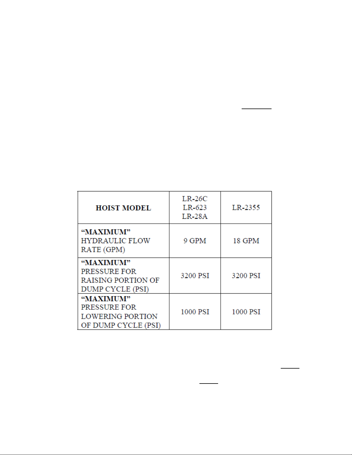
WARNING: Connecting the hoist to a hydraulic system with more pressure (psi) or flow (gpm) than is
recommended by the hoist manufacturer can cause the hoist to fail during the dumping of a load.
This could lead to damage, serious injury, or death. Be sure you have the correct pressure and
flow.
Model LR-26C, LR-623, LR-28A, & LR-2355 Sub-Frame Hoist Installation and Operation Manual
Stock No. 1657499
Page 4 of 25
Capacities are based on the following:
1. Water level non-diminishing loads.
2. The hydraulic relief pressure set at the maximum 3,200 psi (see page 2 of this manual).
IMPORTANT: Because of variations in applications, the data contained in this sheet is provided only as
a general guide.
Model LR-26C, LR-623, LR-28A, & LR-2355 Sub-Frame Hoist Installation and Operation Manual
Stock No. 1657499
Page 5 of 25
Capacities are based on the following:
1. Water level non-diminishing loads.
2. The hydraulic relief pressure set at the maximum 3,200 psi (see page 2 of this manual).
IMPORTANT: Because of variations in applications, the data contained in this sheet is provided only as
a general guide.
Model LR-26C, LR-623, LR-28A, & LR-2355 Sub-Frame Hoist Installation and Operation Manual
Stock No. 1657499
Page 6 of 25
Capacities are based on the following:
1. Water level non-diminishing loads.
2. The hydraulic relief pressure set at the maximum 3,200 psi (see page 2 of this manual).
IMPORTANT: Because of variations in applications, the data contained in this sheet is provided only as
a general guide.
Model LR-26C, LR-623, LR-28A, & LR-2355 Sub-Frame Hoist Installation and Operation Manual
Stock No. 1657499
Page 7 of 25
Capacities are based on the following:
1. Water level non-diminishing loads.
2. The hydraulic relief pressure set at the maximum 3,200 psi (see page 2 of this manual).
IMPORTANT: Because of variations in applications, the data contained in this sheet is provided only as
a general guide.
Model LR-26C, LR-623, LR-28A, & LR-2355 Sub-Frame Hoist Installation and Operation Manual
Stock No. 1657499
Page 8 of 25
"INSTALLATION INSTRUCTIONS"
1. If a LR-26C hoist is to be mounted in this sub-frame, first bolt the two flat brackets to the sub-frame as
shown in Figure 1A LR-26C. Next, position the hoist saddle so that it lines up with the flat edge of the
flat bracket. This will give a mounting distance of 90.50” from the centerline of the hoist saddle shaft to
the centerline of the sub-frame rear hinge.
If a LR-623 or LR-2355 hoist is to be mounted in this sub-frame, first bolt the two flat brackets to the
sub-frame as shown in Figure 1B LR-623 or 1D LR-2355. Next, position the hoist saddle so that it lines
up with the flat edge of the flat bracket. This will give a mounting distance of 95.50” from the centerline
of the hoist saddle shaft to the centerline of the sub-frame rear hinge.
If a LR-28A hoist is to be mounted in this sub-frame, first bolt the two flat brackets to the sub-frame as
shown in Figure 1C LR-28A. Next, position the hoist saddle so that it lines up with the flat edge of the
flat bracket. This will give a mounting distance of 109.81” from the centerline of the hoist saddle shaft to
the centerline of the sub-frame rear hinge.
Ensure that the hoist and sub-frame are positioned squarely on the truck frame before performing any
welding. Mark the location for the rear hinge. This location should be immediately behind a truck cross
member, approximately 32" behind the center of the rear axle on single axle trucks. Refer to Figure 1 and
the charts for the specific hoist model you are installing.
WARNING: Failure to position the hoist at the proper sub-frame mounting point could cause the hoist to
function improperly, leading to possible hoist, body or equipment damage.
WARNING: Failure to position the hoist at the proper sub-frame mounting point could cause the hoist to
function improperly, leading to possible hoist, body or equipment damage.
Model LR-26C, LR-623, LR-28A, & LR-2355 Sub-Frame Hoist Installation and Operation Manual
Stock No. 1657499
Page 9 of 25
WARNING: During the first degrees of the dump cycle, the hoist lower link will move forward. Therefore, it is
important to keep the areas illustrated in Figure 3 open to allow this hoist movement. Failure to do
this will cause the hoist to not operate as intended and may damage the hoist and/or other truck
components.
Model LR-26C, LR-623, LR-28A, & LR-2355 Sub-Frame Hoist Installation and Operation Manual
Stock No. 1657499
Page 10 of 25
2. Attach the sub-frame flat brackets to the sub-frame using 1/2 x 4" bolts, lock washers, and nuts. Refer
to Figure 2.
3. Attach the sub-frame guide plates to the sub-frame using 1/2 x 4" bolts, lock washers, and nuts. The
guide plate should be installed in the next available hole forward of the flat bracket for the LR-26C,
LR-623, or LR-2355. It should be installed in the next available hole rearward of the flat bracket for
LR-28A. Refer to Figure 1.
4. With the hoist in position, attach the sub-frame to the hoist by welding each of the two sub-frame flat
brackets to each of the two hoist saddle brackets. Refer to Figure 2.
5. Position a hoist mounting angle, with three holes, under the saddle bracket located on each side of the
hoist. Secure each large mounting angle to the truck frame by drilling three 17/32" dia. holes and
bolting the mounting angle to the truck frame. Use 1/2 x 1-1/2" bolts, lock washers, and nuts. Finally,
weld each mounting angle to its respective saddle bracket. Refer to Figure 2.
6. Cut off the excess truck frame behind the sub-frame rear hinge. Weld the sub-frame rear hinge to the
truck frame on both sides.
NOTE: The sub-frame model hoists are designed to set on the truck frame, as shown in Figure 1. If a
cross member or some other obstacle in the truck frame interferes with the rear end of the
hoist, the rear end of the hoist can be raised to clear the obstacle. The raising of the hoist rear
end will not affect the lifting capacity, but raising the rear end of the hoist will raise the
mounting height, ie. larger truck body long sills will be required or some cross sill notching
will have to be done.
7. Install each of two lifting shaft as illustrated in Figure 4.