Ruger RC1000S User manual

OPERATOR’S MANUAL
IMPROPER USE
OF THIS EQUIPMENT
CAN BE HAZARDOUS!
SERIAL NUMBER
RC1000S
All operators must read,
understand, and apply all
safety instructions before
operating this equipment.
David Round & Son, Inc.
Ruger Products Division
32405 Aurora Road
Cleveland, OH 44139
Phone: 440-248-4700
www.rugerequipment.com
For safety, one
copy of this manual
must be stored on
the equipment and
referred to by all
operators.

ii
Congratulations on your purchase of a standard design RC1000S Crane. You now own
one of the most versatile cranes in the market. In order to ensure many years of safe and
dependable service, please read this Operator’s Manual before using the equipment. If you
have any questions or need additional information, please contact us at:
Phone: 440-248-4700
Fax: 440-248-8544
www.rugerequipment.com
E-mail: [email protected]
Below is a list of standard accessories that you should have received with your RC1000S
• Operator’s Manual
• Swivel Hook with Safety Latch
• Pump Handle
Designers & Manufacturers of Hydraulic Load Lifting and Material Handling Equipment

iii
Contents
General Information .................................................................................... 1
Receiving and Pre-operational Instructions ............................................. 1
Receiving Procedure ............................................................................... 2-3
Insert Sheets ................................................................................................. 4-5
Maintenance Instructions ................................................................................. 6
Recommended Parts .................................................................................. 7-9
Operational Steps ................................................................................................. 10
Jack Inspection Check List ................................................................................. 11
Jack Service Instructions .......................................................................... 12
Lubrication ............................................................................................................ 13
Safety Tips for Using Ruger Cranes .................................................................... 14
Warranty Information ...................................................................................... 15-17
Designers & Manufacturers of Hydraulic Load Lifting and Material Handling Equipment

CAUTION
DO NOT remove this tag
GENERAL INFORMATION
1. Please include the Model and Serial Number when ordering parts. This information is provided to
you on the front cover of this manual. The Model and Serial Number can also be found on the Serial
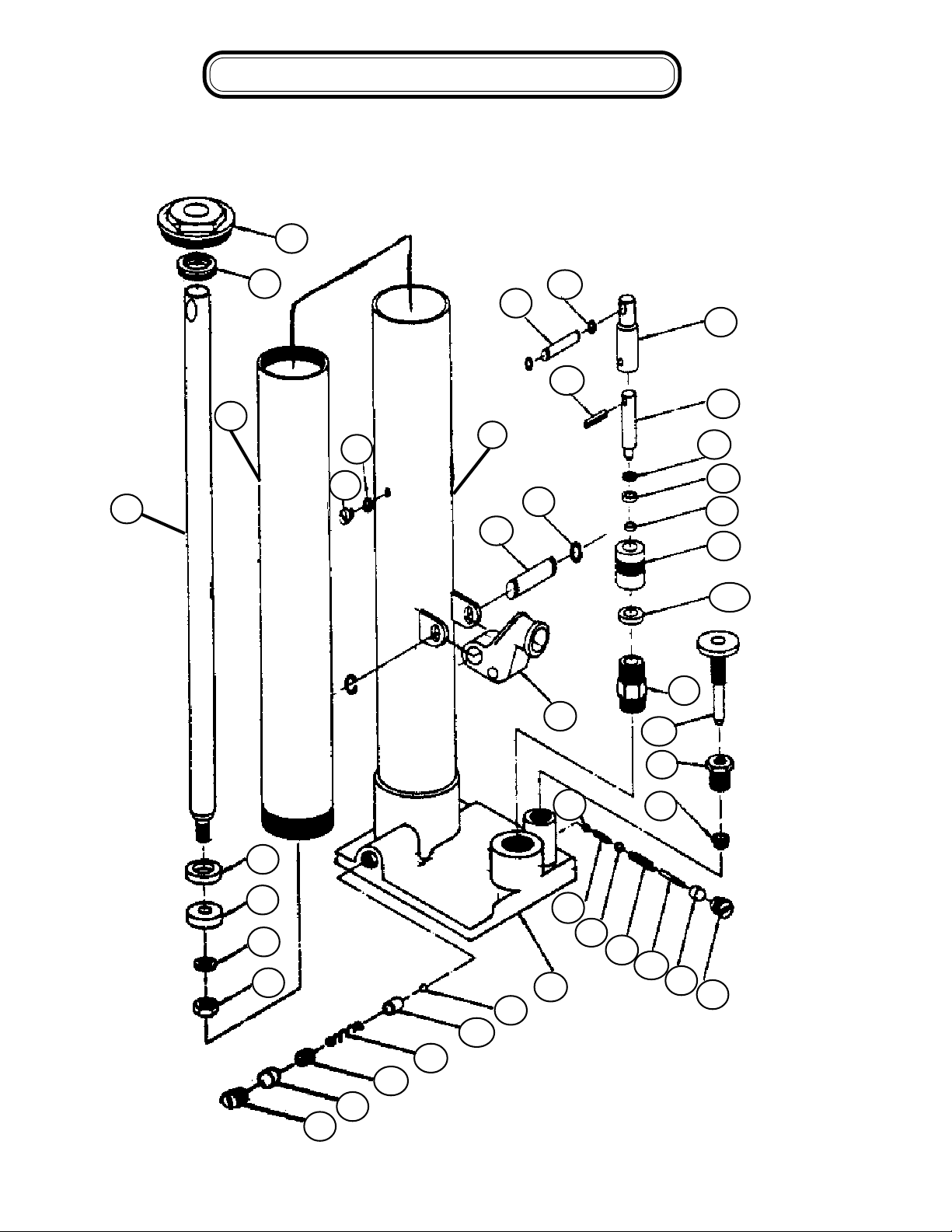
Number tag on the unit located on the mast section of the equipment.
2. Ruger Parts Department can be reached at (440-248-4700), 9 AM to 5 PM EST. time, Monday through Friday
except for holidays.
3. All parts are FOB Solon, OH. Terms are Net 30. Minimum order is $50.00.
4. Quality at Ruger starts with raw materials which are inspected to insure our products will be of good quality
and free from defects. Each product is tested completely and rechecked before shipment.
RECEIVING AND PRE-OPERATIONAL INSTRUCTIONS
Upon receipt of this unit, visually inspect for damage that may have occurred during shipment and report any
damages to the carrier.
In accepting this shipment from Ruger Industries, Inc. the carrier has acknowledged receipt in good condition
and complete as shown on the Packing List and/or Bill of Lading.
Ruger Industries responsibility for this shipment has now ceased. Any shortages or damage must now be
resolved between the carrier and the receiver.
Ruger Industries will not be responsible for loss or damage when you give the transportation company a clear
receipt.
Inspect this material before accepting. DO NOT accept when damage or shortages are visible unless the carrier
makes a damage notation on your freight bill.
Look for and report concealed loss or damage to carrier with 48 hours and request inspection by the carrier.
This is absolutely necessary, otherwise, the transportation companies will not entertain any claim for loss or
damage. If the carrier will not make an inspection, then you should make an affidavit that you notified him/her (on
a certain date) and he/she failed to do so. This, with other papers, will properly support your claim.
Ruger Industries is willing to assist in every possible manner in collecting claims for loss or damage, but this
willingness on Ruger’s part does not include responsibility for collection of claims or assumption of cost of
replacement of damaged or lost materials.
1

2
RECEIVING PROCEDURESRECEIVING PROCEDURES
RECEIVING PROCEDURES
BEFORE ACCEPTING DELIVERY FROM THE CARRIER
In accepting this shipment, the carrier has acknowledged receipt in good condition and complete
as shown on the Packing List and/or Bill of Lading.
RECEIVING INSPECTION CHECK LIST
Check wheels and casters - they should turn freely and be free of dents, cracks
and flat spots.
Check main frame components,legs, forks, booms, handles and sheet metal
for dents, cracks and misalignment.
Check wiring to assure it is securely connected and in good condition.
Check main structure bolts, nuts and pin retainers for tightness.
After visual inspection, make operational test to assure unit is functioning
properly.
Iseverything there? Check packing list to be sure optional equipment is there.
Make sure lifting chain is with crane. Be sure manual pump handle is there.
Paint finish - scratches and scrapes to painted surfaces incurred during
shipment are accepted as necessary evil. Costs of protective crating to protect
paint are so high that it's better to accept a few scrapes to the finish.
Check hoses, fittings and rams for hydraulic leaks.
Hydraulic leaks indicate loose or broken fittings, hoses etc. Hose
and tubing should be free of kinks and buckles.
Check chains and cables for breaks or obstructions.
Check batteries for cracks, leaks. Check electrolyte level.
√√
√√
√
√√
√√
√
√√
√√
√
√√
√√
√
√√
√√
√
√√
√√
√
√√
√√
√
√√
√√
√
√√
√√
√
√√
√√
√

3
RETURNED GOODSRETURNED GOODS
RETURNED GOODS AA
AA
AUTHORIZAUTHORIZA
UTHORIZAUTHORIZA
UTHORIZATIONTION
TIONTION
TION
Packing Slip must accompany all returns.
CREDIT WILL ONLY BE ISSUED AT THE TIME OF
RETURNED GOODS AT THE FACTORY
1) Invoice Number
2) Date of Invoice
3) Serial Number
4) Carrier Name
5) Return Ship Date
6) Reason for Return
There will be a Restocking Charge for all returned purchases.
Customized units are not returnable and are non-refundable.
RECEIVING DOCK DELIVERIES
MONDAY THROUGH FRIDAY
8:00 A.M. TO 4:00 P.M. EST
EXCEPT HOLIDAYS
When calling for a RETURNED GOODS AUTHORIZATION number the following
information must be supplied:
RETURNED GOODS AUTHORIZATION number must be assigned
by the Ruger customer service department for approved returns. This
number must appear on all accompanying paperwork.

1000 lb. Capacity
Ideal for the automotive and truck markets
Boom can be mounted at 5 different
height positions
ACCESSORIES
Barrel Grip
Floor Lock
Steel or Polyurethane Wheels
RC1000S
Prices, Specifications, and Options are subject to Change
Without Notice.
All Ruger products are shipped F.O.B. Solon Ohio 44139
Unit Ships-NMFC #189240 - Class 85
Shipping Wt. 285 lbs
Maximum Value and Safety.
The RC1000S boom
reaches 40” out from ram
connecting point and lifts
1000 pounds.
Tested and exceeds
ANSI/ASME PALD-12C
standards.
Meets ANSI Z.535
STANDARD FEATURES
Meet Ruger’s engineering standards of 150% structural
overload of maximum rated capacity
Completely self-contained hydraulic system with single
action jack
Boom and hydraulics adjust to 5 height locations
Built-in hydraulic overload relief valve
(An original Ruger patent)
Needle type release valve permits pin-point control over
lowering and holding of the heaviest or lightest loads
Snatch hook
Phenolic casters with roller bearing wheels
4
VERSATILE
COMPACT
AFFORDABLE
RELIABLE
David Round & Son, Inc.
Ruger Products Division
32405 Aurora Road
Cleveland, OH 44139
Phone: 440-248-4700
www.rugerequipment.com

MODEL: RC1000S
VERSATILE
COMPACT
AFFORDABLE
RELIABLE
Certain models can be
shipped NEXT DAY.
NOTE:
Ruger can modify
any standard
dimension to meet
specific customer
needs.
PUMPING CYCLES
needed to raise boom
through full
travel : 90.
Model .................................................................... RC1000S
Max. Capacity .................................................... 1000 lbs
Overall Base Length ........................................... 75”
Overall Width ....................................................... 32 1/2”
Overall Height ...................................................... 78”
Width Between Legs ........................................... 24 1/2”
Boom Reach Retracted ...................................... 57 1/2”
Boom Reach Extended ...................................... N/A
Boom Height (lowest position) ........................... 40 1/2”
Boom Height (highest position) .......................... 117 1/2”
Ext. Boom Height (lowest position) ................... N/A
Ext. Boom Height (highest position) .................. N/A
Height of Legs ...................................................... 6”
Wheel Diameter-Load Wheels ............................ 5 ”
Wheel Diameter-Steering Wheels ....................... 4”
David Round & Son, Inc.
Ruger Products Division
32405 Aurora Road
Cleveland, OH 44139
Phone: 440-248-4700
www.rugerequipment.com
5

MAINTENANCE INSTRUCTIONSMAINTENANCE INSTRUCTIONS
MAINTENANCE INSTRUCTIONS
BEFORE EACH USE -
Check the Hydraulic Jack for oil leakage.
Inspect the Safety Swivel Hook with Latch to ensure safe lifting of loads.
WEEKLY -
Check the Pins for excessive wear.
MONTHLY -
Check the Casters for excessive wear or uneven travel.
QUARTERLY -
Check all welded joints.
Serial No. Tag -
Found on the
mast of the
Crane.
6
...a better way to work with heavy loads
Email: [email protected]
Phone: 440-248-4700
Fax: 440-248-8544
David Round & Son, Inc.
32405 Aurora Road
Solon, Ohio 44139
www.davidround.com
NOTE: There is an overload relief valve built into the hydraulic system of every new Ruger Crane. This
safety valve is set at the factory, under measured loadings, and opens at about 10% over the rated
capacity, preventing the crane from lifting.
IF THE CRANE FAILS TO HOLD OR LIFT ITS RATED LOAD.... REMOVE THE CRANE FROM ALL
SERVICE WORK. Contact the factory Customer Service Department at 1-440-248-4700.
When calling the factory, please have your Model
and Serial Number ready, so we may better serve you.

1
20
17
32
31
30
29
28
27
26
25
24
23
22
21
40
39
15
16
8
19
4
9
8
9
5
6
7
10
11
12
13
14
34
35
36
37
2
3
38
18
RECOMMENDED PRECOMMENDED P
RECOMMENDED PARAR
ARAR
ARTSTS
TSTS
TS
33
7

RECOMMENDED PRECOMMENDED P
RECOMMENDED PARAR
ARAR
ARTSTS
TSTS
TS
COMPLETE JACK ASSEMBLIES: 09-004 AND 09-005
REPAIR KITS
PACKING KIT: #768-2 CONSISTS OF ITEMS NO. 2,5,9,28,32 (ALL CRANES)
PUMP PISTON KIT: #768-3 CONSISTS OF ITEMS NO. 23,24,25,26 (ALL
CRANES)
CHECK VALVE KIT: #81053 CONSISTS OF ITEMS NO. 8,9,33,34,35,36
RELIEF VALVE KIT: #80360 CONSISTS OF ITEMS NO. 8,9,10,11,12,13
ITEM NO. PART NO. DESCRIPTION QTY.
1 203051-1 TOP NUT 1
2 203051-2 QUAD RING 1
3 NOT SERV. RAM 1
4 203051-4 SPACER 1
5 203051-5 CUP SEAL 1
6 203051-6 WASHER 1
7 203051-7 HEX JAM NUT 1
8 203051-8 PLUG 2
9 203051-9 SEAL 2
10 203051-10 ADJUSTING SCREW 1
11 203051-11 SPRING 1
12 203051-12 SPRING CAP 1
13 203051-13 BALL 3/16" 1
14 NOT SERV. BASE 1
15 203051-15 HANDLE SOCKET 1
16 203051-16 PIN 1
17 203051-17 PIN RING 2
18 NOT SERV. RESERVOIR TUBE 1
19 203051-19 ROLL PIN 1
20 203051-20 PIN 1
21 203051-21 PIN RING 2
22 203051-22 PUMP LINK 1
23 203051-23 PISTON 1
24 203051-24 BACK-UP RING 1
25 203051-25 CUP SEAL 1
26 203051-26 RETAINER 1
27 203051-27 PACKING NUT 1
28 203051-28 PACKING NUT 1
29 203051-29 PUMP CYLINDER 1
30 203051-30 CONTROL VALVE 1
31 203051-31 PACKING NUT 1
32 203051-32 PACKING 1
33 203051-33 BALL 1/4' 1
34 203051-34 SPRING 1
35 203051-35 BALL 3/8" 1
36 203051-36 SPRING 1
37 203051-37 SPRING SPACER 1
38 NOT SERV. CYLINDER TUBE 1
39 203051-39 WASHER 1
40 203051-40 FILL PLUG 1
8

ORDER PARTS BY PART NAME AND NUMBER.
BE SURE TO INCLUDE MODEL AND SERIAL NUMBER.
All parts are FOB Solon, OH. Terms are /Net 30. Minimum order - $50.00
MODEL ________________________ SERIAL NUMBER ___________________________
9
BOOM EXTENSION CAPACITIES-LBS.
ST'D POSITION-------------------1st POSITION----------------2nd POSITION--------------3rd POSITION
CRANE MODEL N°
EXCEEDING CAPACITIES SHOWN CAN
CAUSE CRANE TO TIP OVER
RESULTING IN DAMAGE TO PROPERTY
AND PERSONAL INJURY.
DAVID ROUND AND SON, INC.
RUGER DIVISION
32405 AURORA RD, SOLON, OHIO 44139 USA
WARNING
211541
NA1000 NA NA
RC1000S
RECOMMENDED PRECOMMENDED P
RECOMMENDED PARAR
ARAR
ARTSTS
TSTS
TS
1
10
7
2
34
56
89
ITEM NO. NAME PART NO.
1 Hydraulic Unit 09-004
2 Load Wheel 07-807
3 Load Axle 07-808
4 Spanner Bushing 07-809
5 Steering Caster with Wheel 07-805
6 Steering Wheel Only 07-806
7 Safety Latch 02-349
8 Jack Handle 7677781
9 Handle Grip 99-511
10 Jack Adapter 7687769

10
Operating the Hydraulic Jack To operate
the hydraulic jack you need to start by setting the release
valve. In order to raise the boom the valve needs to be closed.
To close the valve turn the valve knob clockwise (CW) until it
stops turning. To lower the boom turn the valve knob counter-
clockwise. The further you turn the knob counter-clockwise
(CCW) the faster the boom will lower.
(SEE DIAGRAM # 3).
To raise the boom, close the release valve (CW), insert the jack
handle into the jack lever and move the handle up/down.
(SEE DIAGRAM # 4)
DIAGRAM # 3
DIAGRAM # 4
CCW CW
OPERAOPERA
OPERAOPERA
OPERATIONTION
TIONTION
TIONAL STEPSAL STEPS
AL STEPSAL STEPS
AL STEPS

JACK INSPECTION CHECKLIST
COMPONENTS INSPECT FOR CORRECTIVE ACTION
LEA K S . TIGHTEN TOP NUT (ITEM 1).
CONTROL VALVE, ITEM
30.
BENT. ENTIRE JACK ASSEMBLY MUST BE
REPLACED
RAM, ITEM 3.
DIRT IN THE SYSTEM IS GENERALLY
THE PROBLEM. SERVICE AS
OUTLINED IN SERVICE INSTRUCTIONS.
WILL NOT DEVELOP LOAD.
PUMP VALVE, ITEMS
33, 35, 35, 36, 37, 9, & 8.
WIPE CLEAN OR POLISH WITH FINE
STEEL WOOL. COAT WITH LIGHT OIL.
DIRT, OIL, GREASE.
IF OIL IS NOTED AROUND TOP NUT
(ITEM 1) AND RAM (ITEM 3), RAM
PACKINGS ARE WORN. REPLACE. IF
OIL IS NOTED BETWEEN TOP NUT AND
RE S E RV OIR TUBE (ITE M 18), TIGHTEN
TOP NUT.
HANDLE SOCKET, ITEM
15. WORN, CRACKED OR BROKEN. REPLACE.
ENTIRE JACK ASSEMBLY MUST BE
REPLACED
DEFORMED, ETC.
RESERVOIR TUBE,
ITEM 18 (has metal to
metal fit)
LEAKING AROUND ITEM 31. TIGHTEN OR REPLACE PACKING (ITEM
32).
BENT OR BROKEN. REPLACE RELEASE SCREW
ASSEMBLY.
REPLACE IF ANY OF THESE
CONDITIONS ARE FOUND.
STRAIGHTNESS, SCORE
MARKS, PITTING, HEAD OR
HOLE DEFORMATION, LEAKAGE
AROUND PACKING NUT.
PUMPING PISTON, ITEM
23.
ENTIRE JACK ASSEMBLY MUST BE
REPLACED
BASE, ITEM 14. DEFORMED, BROKEN, ETC.
OIL AROUND TOP NUT.
LINKAGE PINS, ITEMS
16, 19, & 20. WORN OR BENT.
REPLACE. ALIGNMENT OF PUMP
PISTON IS DEPENDENT ON THESE
PINS.
11

If the crane fails to hold or lift its rated load, inspect and repair using the following
information. All parts referenced are shown in jack breakdown. Remove jack from
crane for all service work.
A. Control Valve (Item 30) – Turn jack upside down. Remove valve stem by
turning counter-clockwise. Inspect valve for wear or nicks. Replace if
necessary. If stem appears to be smooth, inspect seat for chips, dirt, or other
forms of contamination. Remove if necessary.
B. Pump Valves – The valves and valve seats must be clean and in mirror
condition. Dirt occasionally builds up between the valve and valve seat,
preventing a tight seal between the two.
1. Inspect pump valve by first opening the control valve (Item 30).
Remove plug (Item 8). Carefully remove the pressure seal (Item 9)
by using a small dull tool. Be careful not to rupture the body of the
seal. The springs and balls may be removed by tipping the hydraulic
unit on its side.
2. Place the jack on its side with the pump valve holes up. This will
prevent the fluid from running out.
3. With the aid of a light, inspect the valve chamber for dirt or other
contamination. Ball seats must be free from nicks or scratches. If
the seals are deformed, the jack should be taken to a qualified
service depot for repair. Balls and springs must be clean and free
from dirt, corrosion, nicks, scratches, or other forms of damage.
4. If all parts appear to be in good working condition, use air pressure
to blow out any dirt particles before reassembly.
5. Reassemble in reverse order.
Check oil level and bleed air from the system before use. With control valve open and
ram retracted, place jack in an upright position. Remove filler screw (Item 40). The
oil level should be level with filler screw opening. If oil is not at this level, fill reservoir
with hydraulic jack oil. (SAE #10) non-detergent motor oil or equal). DO NOT USE
HYDRAULIC BRAKE FLUID. If there is too much oil in the reservoir it will run out
when filler screw is opened. The air space above the filler screw is necessary to
prevent a vacuum from forming at the top of the reservoir. After correcting the
amount of fluid in the reservoir, replace the filler screw. Leave the control valve open
and pump the handle a few times. This will bleed air from the hydraulic system.
JACK SERVICE INSTRUCTIONS
12

LL
LL
LUBRICAUBRICA
UBRICAUBRICA
UBRICATIONTION
TIONTION
TION
13
ITEM NO. DESCRIPTION OIL WHEN
1 Boom Pivot Point Chassis Lube Apply Monthly
2 Jack Mount Pivot Point Chassis Lube Apply As Needed
3 Cylinder Ears on Boom Chassis Lube Apply As Needed
4 Load Wheel Axles Chassis Lube Apply Monthly (Do Not Spray Wheels)
5 Steering Wheel Axles Chassis Lube Apply Monthly (Do Not Spray Wheels)
Chassis Lube = White High Pressure Lithium Grease Spray
1
2
3
54

14
Safe operation of this
equipment is your
responsibility.
NO PERSON shall operate
this crane unless they have
received instructions for its
proper use from a qualified
person and have completely read the operators
manual.
Operator
When more than one person is involved in the
operation of the crane, one person should supervise
and give all orders, to avoid confusion and to
promote safety.
Refuse to handle loads
until safety has been
assured.
Test the stability of the
system before using.
Adjust if necessary.
Always transport loads as close to the floor as
possible.
Keep hands and feet clear
of crane base and wheels.
Also, in facing away from
crane while pulling, maintain
distance to prevent crane
from rolling into your own
heel.
Use standard hand signals when operating with
other persons. Make sure all concerned understand
signals to be used.
Make sure floor area over
which the crane travels is
level and free from debris
and other materials that
may interfere with normal
crane travel.
Use caution when working
near electrically charged lines or equipment.
DO NOT use your crane to lift more than its rated
load. Load ratings are based on new equipment.
Age, wear, improper maintenance, and improper use
will reduce load ratings. DO NOT continue operation
of a crane damaged by misuse or overloading.
Never use two or more cranes to lift a load greater
than the capacity of a single crane - a shifting load
may place entire load on one unit.
Apply the load evenly, do not jerk or bounce or allow
the load to swing. Avoid violent motion and shock
loads.
People
DO NOT lift or lower people or things over people
with this equipment.
DO NOT exceed load ratings of other components in
the load lifting system-cables, slings, etc.
Never walk, stand or work
under a raised load.
Obey plant safety rules; obey a stop signal from
anyone.
SAFETY TIPS FOR USING RUGER CRANESSAFETY TIPS FOR USING RUGER CRANES
SAFETY TIPS FOR USING RUGER CRANES
Never leave a raised load
unattended.
Make sure load clears nearby stockpiles, machines
or other obstructions when raising, lowering or
moving the load.
Make sure load is totally disconnected from any
fasteners before lifting and transporting.
Avoid sudden acceleration or deceleration of the
crane. DO NOT make sudden sharp turns while
moving the crane, loaded or empty.
Keep hands away from
load bearing chains,
cables and slings while
operating.

15
We warrant that our standard products will be of good merchantable quality, free from defects in material and
workmanship, and will conform to the characteristics represented by us for:
Subject to the following terms and conditions:
(1) The products have not been misused, abused, neglected or damaged in any way, or operated in a manner
inconsistent with our stated purpose and applicable instructions for use whether given before, at or after sale
including any provided mailings to you or posted on our web site at any time and subject to change without notice.
(2) The products have not been altered, serviced, upgraded, or changed in any manner except by us.
(3) The products were not damaged in shipping, or thereafter in used or storage.
(4) Proper maintenance has been performed on the products on a regular basis per the standard schedule.
(5) Regular inspection and testing by us has occurred per the standard schedule and fees which under no circum-
stances will allow for inspection and testing on intervals greater than every 2 years.
(6) The products are not for rental use.
(7) Notice is given to us within three business days of discovery of noncompliance of the product.
(8) The products have not been sold, leased or otherwise transferred out of title and control of the original
purchaser.
1 Year On metal frames, castings and weldments
1 Year On hydraulic seals, wiring and hoses.
1 Year On contactors, drive units, motors, hydraulic
rams, pumps and valves
1 Year On all other parts
If all of the above terms and conditions are met, and a product does not comply in our sole judgment with the
warranty during the warranty period, we will repair or replace it in our sole discretion at our cost which is limited to
our standard labor and materials costs, and shipping or travel costs if needed by non-expedited means. It is
understood that this warranty is in lieu of and excludes all other warranties, express or implied, including any
warranties extending beyond the description on the face of this document and including any warranties of mer-
chantability or fitness as provided under operation of law, and that our sole liability hereunder is expressly limited to
the repair or replacement of the products not complying with the warranty.
If any one of the above terms and conditions are not met, the warranty is void and unenforceable.
We are not liable under any circumstances for special, indirect, incidental, consequential or punitive damages of
any nature including, but not limited to, loss of profit, delays or expenses, and under no circumstances shall our
liability under this warranty ever exceed the actual purchase price paid for the products. We do reserve the right to
make changes or improvements to any product including as needed during a repair or replacement, or as arise from
any inspection or testing.
WARRANTY

16
It should be verified that the equipment will do the job for which it was ordered for.
The equipment should be cycled through all its functions several times.
The section in the OPERATOR'S MANUAL which covers steps to be taken before placing the equipment
in service should be followed.
Included with the equipment is a receiving inspection check list. Do not relinquish your rights to claim for
"CONCEALED DAMAGES" until this check list has been completed.
BEFORE Product is placed in service:
Upon delivery of a new piece of equipment, here is a series of useful steps to be taken by the distributor or
customer to help prevent or reduce difficulty in event of future warranty claims. These steps are not the
responsibility of the manufacturer. The suggestions are made to help eliminate avoidable problems and do not
enlarge or reduce the customers rights under the standard Ruger warranty.
The MANUFACTURER,when there is a problem in materials, assembly or design.
The DISTRIBUTOR, who may have made a bad choice of equipment or model for the job.
The CUSTOMER,who may have brought about the failure because of misuse, abuse, neglect of
maintenance, or wear of a consumable material not covered by warranty.
The CARRIER,who accepted the equipment in normal working condition and delivered it in damaged
condition.
THIRD - To establish who should pay for the repair:
FIRST - To get the customer's equipment into satisfactory operation.
SECOND -To determine a fair cost for accomplishing the above.
The objectives of the Ruger warranty and its administration are:
If a problem occurs with a Ruger product, the ideal solution will get the equipment back into
service promptly with costs of the repair paid by the appropriate party -- either the carrier,
the customer, the distributor, the factory or some combination of these.
WARRANTYWARRANTY
WARRANTYWARRANTY
WARRANTY

17
WW
WW
WARRANTY INFORMAARRANTY INFORMA
ARRANTY INFORMAARRANTY INFORMA
ARRANTY INFORMATIONTION
TIONTION
TION
4. Warranty claims are to be deducted from Ruger invoices.
3. Field assistance is being furnished at factory expense.
2. Shipping charges in or out on replacement parts are being paid by
the factory.
1. Non-factory parts are being invoiced to the factory.
Prior factory approval is REQUIRED when:
2. Solicit factory approval before incurring any costs at all. In this case, the distributor or customer
should get all preliminary details possible and call the FACTORY SERVICE DEPARTMENT at
800-257-8437. In this way, a preliminary diagnosis and factory commitment can be obtained on
ceilings for travel, labor, parts, and freight. Thus, the distributor knows where he stands with the factory
and needed parts can be sent off. If the factory authorizes the supply of parts under warranty by the
distributor from his own stock, they should be invoiced.
When factory compensation appears justified, the factory maintains sole final discretion to determine if the
malfunction is covered under the terms of the warranty. In this situation, the distributor or customer has the
choice of:
If the problem is the fault of the carrier (damage in transit), or the distributor (misapplication of the product),
costs of repairs should be billed to and honored by them directly.
In the event investigation of a service problem by the distributor discloses that correction should be at the
customer's expense because of misuse or neglect, the customer should be notified of this before repair work
begins and the distributor should bill the customer directly.
1. Proceeding with repairs and submission of invoices for factory payment or credit, relying on the
fairness of Ruger's service people to back up the customer, the distributor and the equipment to the
maximum responsible limit subject to the terms of the warranty itself, or.....
Table of contents
Other Ruger Construction Equipment manuals
Popular Construction Equipment manuals by other brands

Chicago Pneumatic
Chicago Pneumatic CP83100 Operator's manual

Manitowoc
Manitowoc MLC165-1 Service maintenance manual

Tadano
Tadano TR-150XL-4 Service manual

IMER
IMER Minibeta 1126606 Operating, maintenance, spare parts manual

Fairport
Fairport F14-35 Operation, spare parts and service manual

Thern
Thern 5BH5 owner's manual

Bomag
Bomag BW 211 D-4 Service manual

National Crane
National Crane NBT40-2 Series Operator's manual

BUFFALO TURBINE
BUFFALO TURBINE BT-MDC2 Original instructions and parts manual

Svedala-Demag
Svedala-Demag DF 115 C operating instructions

RaycoWylie
RaycoWylie i3500 quick start guide

ECOVOLVE
ECOVOLVE ED1000 Operator's handbook