Runfine RFBW12304 User manual

Model :RFBW12304
Model :RFBE 12304
Model :RFBG 12304
Inspect product prior to installation. Contact info@runfinegroups.com
prior to returning product to retailer.
Inspeccione el producto antes de su instalación. Póngase en contacto con
[email protected] antes de devolver el producto al vendedor.
Page 1
Wall Cabinet Operators’ Manual
Manual de Operadora del
Gabinete de pared

PARTS LIST
A. LEFT SIDE PANEL / PANEL LATERAL IZQUIERDA 1PC
B. RIGHT SIDE PANEL / PANEL LATERAL DERECHO 1PC
C. TOP PANEL / PANEL SUPERIOR 1PC
D. BOTTOM PANEL / PANEL INDERIOR 1PC
E. BACK DOWN CROSS BAR / BARRA TRANSCERSAL INFERIOR POSTERIOR 1PC
F. BACK TOP CROSS BAR / BARRA TRANSCERSAL SUPERIOR POSTERIOR 1PC
G. ADJUSTABLE SHELF PANEL / PANEL DEL ESTANTE AJUSTABLE 1PC
H. UPPER BACK PANEL / PANEL SUPERIOR POSTERIOR 1PC
I. LOWER BACK PANEL / PANEL INFERIOR POSTERIOR 1PC
J1. LEFT DOOR PANEL / PANEL IZQUIERDA PUERTA 1PC
J2. RIGHT DOOR APNEL/ PANEL DE DERECHA PUERTA 1PC
K. TOWEL BAR / TOALLERO 1PC
Page 2

HARDWARE
1. DOOR KNOB / PERILLA DE LA PUERTA 2PCS
2. DOOR KNOB SCREW (18MM L) / TORNILLO PARA LA PUERTA PERILLA (18MM L) 2PCS
3. CAM LOCK NUT & BOLT / TUERCA & PERNO CAM 12SETS
4. WOOD DOWEL / TACO DE MADERA 12PCS
5. SHELF SUPPORTS / SOPORTA DE ESTANTE 4PCS
6. DOOR MAGNET AND SCREW / IMÁN Y TORNILLO DE LA PUERTA BLANCA 2SETS
7. WOOD SCREW (12MM L) / TORNILLO DE MADERA (12MM L) 23PCS
8. DOOR HINGES & SCREW / BISAGRAS & TORNILLO 4SETS
9. PLASTIC ANCHOR & SCREW / BISAGRAS & TORNILLO DE PLÁSTICO 2SETS
Page 3

ASSEMBLY OF THE SIDE PANELS, THE BACK TOP CROSS BAR, THE BACK DOWN CROSS BAR, THE BOTTOM
PANEL AND THE TOWEL BAR(STEP 1)- #A
ASAMBLEA DE LOS PANELES LATERALES, BARRA TRANSCERSAL INFERIOR POSTERIOR, BARRA
TRANSCERSAL SUPERIOR POSTERIOR, PANEL INFERIOR Y EL TOALLERO (PASO 1)- #A
Figure 1
FLAT HEAD
SCREWDRIVER
PHILLIPS
SCREWDRIVER
TOOLS REQUIRED (NOT INCLUDED)
Insert the camlock bolts (3) and the wood dowels (4) into the pre-drilled hole of the left side panel (A), the right side
panel (B), the botttom panel (D), the back top cross bar (F) and the back down cross bar (E) as shown (Figure
1 )
Inserte los pernos camlock (3) y las tacos de madera (4) en el agujero previamente taladrado del panel lateral
izquierdo (A), el panel lateral derecho (B), el panel inferior (D), la barra transversal superior trasera (F) y la
barra transversal posterior (E) como se muestra (Figura 1)
Page 4
Please read instructions before assembly.
Perform assembly on a carpeted surface to prevent scratching.
This assembly process require at least two people.
Por favor, lea las instrucciones antes del montaje.
Realizar el montaje sobre una superficie enmoquetada para
evitar que se raye.
Este proceso de montaje requiere al menos dos personas.

ASSEMBLY OF THE SIDE PANELS,BACK TOP CROSS BAR, BACK DOWN CROSS BAR, BOTTOM PANEL & TOWEL
BAR(STEP 1)- #B
ASAMBLEA DE LOS PANELES LATERALES, BARRA TRANSCERSAL INFERIOR POSTERIOR, BARRA
TRANSCERSAL SUPERIOR POSTERIOR, PANEL INFERIOR Y EL TOALLERO (PASO 1)- #B
Figure 2
Attach the side panels (A) &(B) to the back top cross
bar (F), the bottom panel (D) and the back down
cross bar (E) by inserting camlock bolts(3) and
wood dowels (4),
Insert towel bar (K) into the pre-drilled hole of left &
right side panel (A,B) as shown (Figure 2).
Fije los paneles laterales (A) y (B) a la barra transversal
superior trasera (F), el panel inferior (D) y la barra
transversal inferior trasera (E) mediante la
inserción de tornillos camlock (3) y tacos de
madera (4),
Inserte toallero (K) en el orificio pre-perforado del panel
lateral izquierdo y derecho (A, B), como se
muestra (Figura 2).
Insert the camlock nut (3) into the pre-drilled hole of the
back top cross bar (F), the bottom panel (D) and
the back down cross bar (E).
Tighten using Phillips head screwdriver as shown
(Figure 3)
Inserte la tuerca camlock (3) en el agujero previamente
taladrado de la barra atrás top cruz (F), el panel
inferior (D) y la barra transversal hacia abajo (E).
Apriete con un destornillador de cabeza Phillips como
se muestra (Figura 3)
Figure 3
Page 5

ASSEMBLY OF THE TOP PANEL(STEP 2)
ASAMBLEA DEL PANEL SUPERIOR (PASO 2)
Figure 4
Insert the cam lock bolts (3) into the pre-drilled hole of the top panel (C).
Attach the top panel (C) to the side panels (A) & (B) as shown (Figure 4).
Inserte los pernos de bloqueo de leva (3) en el agujero previamente taladrado
del panel superior (C).
Fije el panel superior (C) a los paneles laterales (A) y (B) como se muestra
(Figura 4).
Insert the camlock nut (3) into the pre-drilled hole of the side panels (A) & (B).
Tighten using Phillips head screwdriver.
Screw door magnets (6) to the top panel (C) using the magnet screw (6) as
shown (Figure 5).
Inserte la tuerca camlock (3) en el agujero previamente taladrado de los
paneles laterales (A) y (B).
Apriete con un destornillador Phillips.
Imanes de las puertas de tornillo (6) al panel superior (C) con el tornillo de
imán (6) como se muestra (Figura 5).
Figure 5
Page 6

ASSEMBLY OF THE BACK PANEL(STEP 3)
ASAMBLEA DEL PANEL POSTERIOR (PASO 3)
Figure 6
Attached the back panel (H)& (I) to the cabinet using the
wood screws (7) as shown (Figure 6).
Se adjunta el panel trasero (H) (I) al gabinete con los
tornillos de madera (7) como se muestra (Figura 6).
Screw the door hinges (8) to the door panel(J) using the hinge screw (8).
Attach door knob (1 ) with knob screws (2) onto the door panel (J) as shown (Figure 7).
Tornillo de las bisagras de la puerta (8) al panel de la puerta (J) utilizando el tornillo de
la bisagra (8).
Adjuntar pomo de la puerta (1) con tornillos de cabeza (2) en el panel de la puerta (J)
como se muestra (Figura 7).
Figure 7
ASSEMBLY OF THE DOOR PANEL & DOOR KNOB(STEP 4)
ASAMBLEA DE LA PUERTA DEL PANEL DE PUERTA Y MANDO (PASO 4)
Page 7
Attach the door panels (J) to the side panels (A) & (B) using the door
hinges and the hinge screws (8) (Figure 8).
Fije los paneles de las puertas (J) a los paneles laterales (A) y (B) usando
las bisagras de las puertas y los tornillos de la bisagra (8) (Figura
8).
Figure 8

Figure 9
Figure 10
Page 8
WALL MOUNT INSTALLATION(STEP 5)
INSTALACIÓN MONTAJE EN PARED (STEP 5)
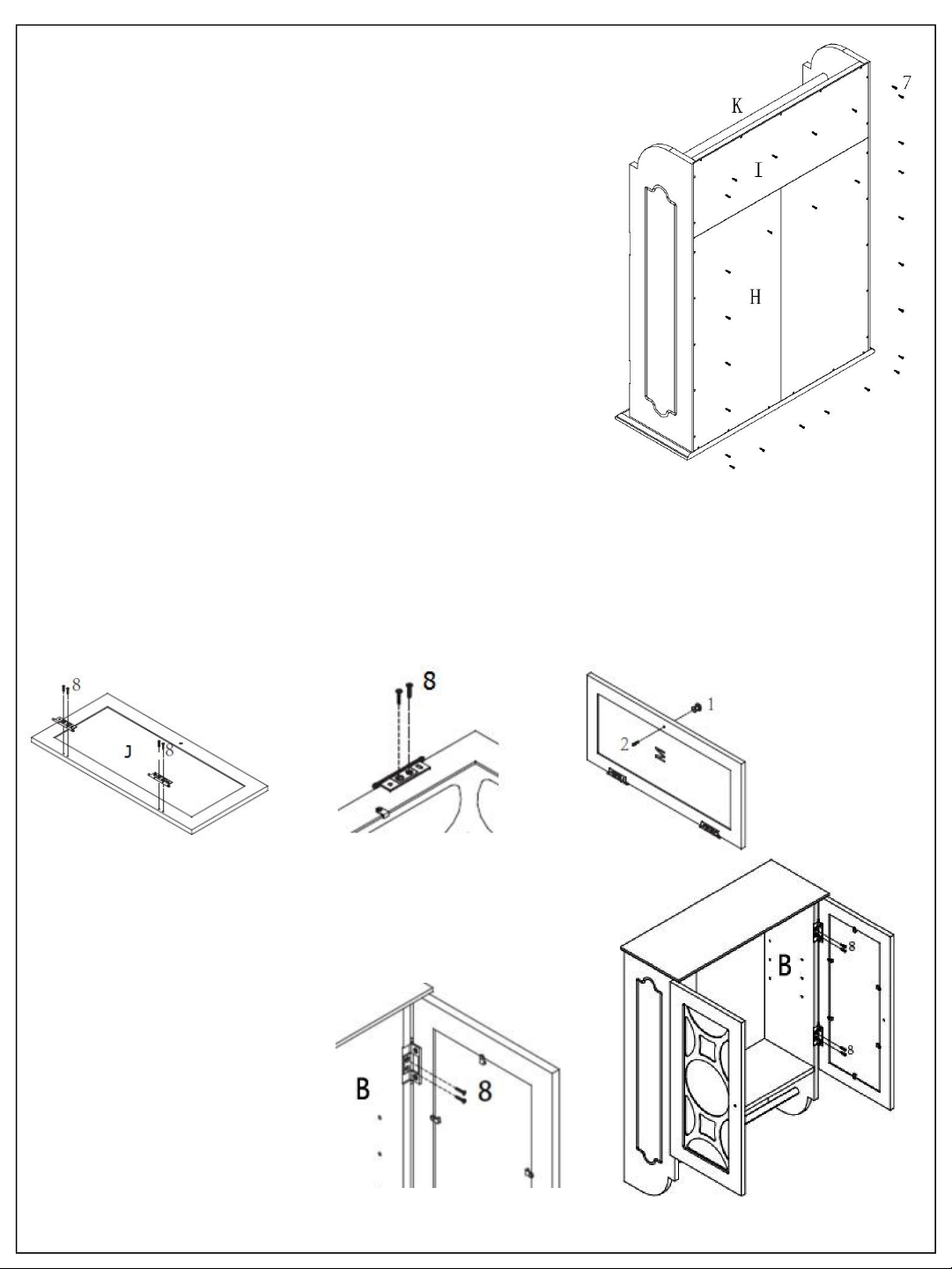
ASSEMBLY OF THE ADJUSTABLE SHELF(STEP 6)
ASAMBLEA DE LA PLATAFORMA AJUSTABLE (PASO 6)
Insert the shelf support (7) into pre-drilled holes of side
panels, then place adjustable shelf (G) onto shelf
supports as shown (Figure 10).
Inserte el soporte del estante (7) en los agujeros
previamente perforados de los paneles laterales, a
continuación, coloque estante ajustable (G) en la
repisa soportes como se muestra (Figura 10).
Locate a desired position on the wall on which to mount
the cabinet.
If wall studs are located at the exact screw positions of the
cabinet cross bars, then mount the cabinet to the
wall using mounting screws (9).
If the wall behind the cross bars is hollow, then drill
through all mounting holes to mark hole positions
on the wall.
Remove the cabinet from the wall.
Drill holes through the marked positions on the wall and
insert plastic anchors (9) into the wall.
Place the cabinet back on the wall and drill mounting
screws (9) through back top cross bar (F) holes to
secure the cabinet to the wall (Figure 9).
Localice la posición deseada en la pared para montar el
gabinete.
Si los montantes están situados en las posiciones exactas
de tornillo de las barras transversales del gabinete y
luego montar el gabinete a la pared usando los
tornillos de montaje (9).
Si la pared detrás de las barras cruzadas es hueca, luego
perforar los agujeros de montaje para marcar las
posiciones de agujero en la pared.
Retire el gabinete de la pared.
Taladre agujeros en las posiciones marcadas en la pared e
inserte taquetes de plástico (9) en la pared.
Coloque el gabinete a la pared y perforar los tornillos de
montaje (9) Cruz vuelta superior de la barra orificios
(F) para fijar el gabinete a la pared (Figura 9).
This manual suits for next models
2
Table of contents
Other Runfine Indoor Furnishing manuals

Runfine
Runfine RFVA0069 User manual

Runfine
Runfine RFVA0069B User manual

Runfine
Runfine RFVAB0008 User manual

Runfine
Runfine RFBW01011 User manual

Runfine
Runfine RF110140 User manual

Runfine
Runfine RFBW12303 User manual

Runfine
Runfine Etagere RFBW12301 User manual

Runfine
Runfine DESA 8 Drawer Dresser User manual

Runfine
Runfine RFBW01014 User manual
Popular Indoor Furnishing manuals by other brands

Regency
Regency LWMS3015 Assembly instructions

Furniture of America
Furniture of America CM7751C Assembly instructions

Safavieh Furniture
Safavieh Furniture Estella CNS5731 manual

PLACES OF STYLE
PLACES OF STYLE Ovalfuss Assembly instruction

Trasman
Trasman 1138 Bo1 Assembly manual

Costway
Costway JV10856 manual