www.victorruoshui.co.kr
이자료는 저작권법에 따라 보호받는 저작물이므로 무단배포 및무단복제를 금하며, 내용을 이용하려면, 한국 VictorRuoshui 社
의서면동의를 받아야 합니다.
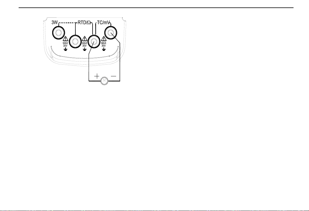
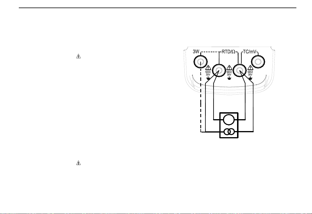
Figure 5-1
5. Press 〔〕/〔〕key , change the value of set bit,
and the value can carry or abdicate automatically,
and hold the key, the value will alter constantly after
one second.
6. Press the 〔ZERO〕key, the output will be set as
000.00mV or 0000.0mV.
(2) Thermocouple (TC )simulate output
1. Insert the testing probe into the jack of the meter‟s
output terminal (TC/mV), and connect the other end
with input terminal of the Users‟ meter, see Figure
5-1;
2. Press 〔FUN 〕key , select thermocouple(TC)
function, and display „C‟ unit and „R‟ graduation no.;
3. Press 〔RANG 〕key, select corresponding
graduation no.;
4. Press 〔〕/〔〕key, select output set bit;
5. Press 〔〕/〔〕key , change the value of set bit,
and the value can carry or abdicate automatically,
and hold the key, the value will change constantly
after one second.
6. Automatic compensation of cold junctions
When calibrating meter with temperature cold
junction compensation directly, press 〔RJ-ON〕key to
start the automatic compensation function of cold
junctions of this meter, and it will output the necessary
temperature thermoelectric force, and display „RJ-ON‟.
(See Section Seven for the accuracy of cold junction
compensation), and :
Output thermoelectric force = the corresponding
thermoelectric force of set temperature –the
corresponding thermoelectric force of room temperature
* The Users need to wait for 2 seconds when
starting the interior cold junction compensation of
the meter and the meter will make automatic
compensation every 10 seconds
* When the operation ambient temperature change,
the Users need to wait until the interior
compensation sensor stabilizes (about 10 minutes)
and then use
* If the Users do not use the automatic compensation
function of this meter, press the〔RJ-ON〕key and
the symbol‘RJ-ON’will not display any more
7. Press〔ZERO〕key, the output will be set as 0000C
(R, S graduation), 400C(B graduation),