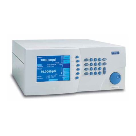
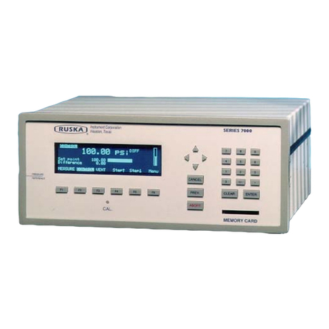
Ruska Instrument 7215 User manual

DIGITAL PRESSURE
CONTROLLER
MODEL 7215
MODEL 7215i
MODEL 7215xi
USER’S MANUAL
RUSKA INSTRUMENT CORPORATION
10311 WESTPARK DR., HOUSTON, TEXAS 77042
(713) 975-0547 FAX: (713) 975-6338
E-MAIL: ruska@ruska.com !http://www.ruska.com
Release: 7215-1D01
Revision: C
Date: 10/13/00

ii
WARRANTY
Ruska Instrument Corporation warrants its products to conform to or exceed the specifications as set forth
in its catalogs in use at the time of sale and reserves the right, at its own discretion, without notice and
without making similar changes in articles previously manufactured, to make changes in materials, designs,
finish, or specifications. Ruska Instrument Corporation warrants products of its own factory against defects
of material or workmanship for a period of one year from date of shipment.
Liability of Ruska Instrument Corporation under this warranty shall be limited to replacing, free of charge
(FOB Houston, Texas), any such parts proving defective within the period of this warranty, but will not be
responsible for transportation charges or consequential damages.
This warranty is not made for products manufactured by others which are illustrated and described in Ruska
catalogs or incorporated in Ruska products in essentially the same form as supplied by the original
manufacturer. However, Ruska Instrument Corporation agrees to use its best efforts to have original
suppliers make good their warranties.

iii
COPYRIGHT NOTICE
Copyright © 1997 by Ruska Instrument Corporation. All rights reserved. This document may not be
reproduced in part or in whole without the express written consent of Ruska Instrument Corporation.
DISCLAIMER
No representations or warranties are made with respect to the contents of this user’s manual. Further, Ruska
Instrument Corporation reserves the right to revise this manual and to make changes from time to time in
the content hereof without obligation to notify any person of such revision.
TRADEMARK NOTICE
®is a registered trademark of Ruska Instrument Corporation.
Trademarks or tradenames are subject to state and federal laws concerning their unauthorized use or other
infringements. The fact that the product marks or names in this manual do not bear a trademark symbol
DOES NOT mean that the product name or mark is not registered as a trademark or tradename. Any queries
concerning the ownership or existence of any trademarks or tradenames mentioned in this manual should be
independently confirmed with the manufacturer or distributor of the product.

iv
REVISION NOTICE
RELEASE
NUMBER REV DATE OF
RELEASE DESCRIPTION
7215-1D01 A 08/30/97 Original release
7215-1D01 B 08/01/99 Incorporated 7215iand 7215xi
7215-1D01 C 10/13/00 Changes in Section 7.2 per DC/RO-22717.

v
REVISION HISTORY
RELEASE 7215-1D01 Revision A (8/30/97)
Original release
RELEASE 7215-1D01 Revision B (08/01/99)
Incorporated 7215iand 7215xi
Per ECO 17806
RELEASE 7215-1D01 Revision C (10/13/00)
Changes in Section 7.2 per
DC/RO-22717

vi
SAFETY SUMMARY
The following are general safety precautions that are not related to any specific procedures and do not
appear elsewhere in this publication. These are recommended precautions that personnel must understand
and apply during equipment operation and maintenance to ensure safety and health and protection of
property.
KEEP AWAY FROM LIVE CIRCUITS
Operating personnel must at all times observe safety regulations. Do not replace components or make
adjustments inside the equipment with the voltage supply connected. Under certain conditions, dangerous
potentials may exist when the power control is in the off position due to charges retained by capacitors. To
avoid injuries, always remove power from, discharge, and ground a circuit before touching it.
DO NOT SERVICE OR ADJUST ALONE
Do not attempt internal service or adjustment unless another person capable of rendering aid and
resuscitation is present. RESUSCITATION
Personnel working with or near dangerous voltages shall be familiar with modern methods of resuscitation.
Such information may be obtained from your local American Medical Association.
ELECTRO STATIC DISCHARGE SENSITIVE PARTS
CAUTION: Electrostatic discharge sensitive (ESDS) is applied to low power, solid-state
parts which could be damaged or destroyed when exposed to discharges of static
electricity. Maintenance personnel are often not aware that an ESDS part has
been damaged or destroyed because electrostatic discharges at levels less than
4,000 volts cannot be seen, felt, or heard.
When the ESDS symbol appears between a paragraph number and paragraph title, the entire
paragraph and all subparagraphs shall be considered ESD sensitive. When the ESDS symbol appears
between a step number and the step test, the step shall be considered ESD sensitive.
COMPRESSED GAS
Use of compressed gas can create an environment of propelled foreign matter. Pressure system safety
precautions apply to all ranges of pressure. Care must be taken during testing to ensure that all pneumatic
connections are properly and tightly made prior to applying pressure. Personnel must wear eye protection to
prevent injury.
PERSONAL PROTECTIVE EQUIPMENT
Wear eye protection approved for the materials and tools being used.
INERT GASES
Operation of pressure equipment may be accompanied by the discharge of inert gases to the atmosphere.
The result is a reduction of oxygen concentration. Therefore, it is strongly suggested that exhaust gases not
be trapped in the work area.

vii
TABLE OF CONTENTS
WARRANTY ...............................................................................................................................ii
COPYRIGHT NOTICE...............................................................................................................iii
REVISION NOTICE ...................................................................................................................iv
REVISION HISTORY..................................................................................................................v
SAFETY SUMMARY..................................................................................................................vi
TABLE OF CONTENTS............................................................................................................vii
SECTION 1: GENERAL INFORMATION
1.1 INTRODUCTION.............................................................................................. 1
1.2 GENERAL INFORMATION.............................................................................. 1
1.3 FEATURES...................................................................................................... 1
1.4 STANDARD EQUIPMENT & OPTIONS........................................................... 2
SECTION 2: THEORY OF OPERATION
2.1 INTRODUCTION.............................................................................................. 5
2.2 POWER SUPPLY ............................................................................................ 5
2.3 ELECTRONICS MODULE................................................................................ 6
2.3.1 CONTROL BOARD ........................................................................... 6
2.3.2 MICROPROCESSOR BOARD .......................................................... 6
2.3.3 ANALOG CONTROL BOARD............................................................ 7
2.3.4 IEEE-488 INTERFACE...................................................................... 7
2.3.5 FRONT PANEL.................................................................................. 7
2.4 PNEUMATICS MODULE.................................................................................. 8
2.4.1 MEASURE MODE PNEUMATICS................................................... 10
2.4.1.1 REFERENCE PORT........................................................ 10
2.4.1.1.1 BAROMETRIC SENSOR ............................. 11
2.4.1.2 TEST PORT .................................................................... 11
2.4.1.3 VENT PROCEDURE........................................................ 11
2.4.2 CONTROL MODE PNEUMATICS................................................... 11
2.4.2.1 PRESSURE SUPPLY PORT ........................................... 11
2.4.2.2 VACUUM SUPPLY (EXHAUST) PORT ........................... 11
2.4.2.3 PRESSURE CONTROL................................................... 11
2.5 CONTROL STRATEGY ................................................................................. 12
2.5.1 INNER VS OUTER CONTROL LOOP............................................. 12

viii
2.5.2 LOW OVERSHOOT MODE............................................................. 12
2.5.3 NORMAL MODE.............................................................................. 12
2.5.4 ALIGNMENT OF INNER LOOP WITH OUTER LOOP..................... 12
2.5.4.1 VACUUM AND SIMULATED ABSOLUTE SYSTEMS...... 12
2.5.5 PID CONTROL................................................................................ 13
2.6 TRANSDUCER MODULE.............................................................................. 13
2.6.1 QUARTZ BOURDON TUBE SENSOR (TRANSDUCER01)............. 13
2.6.2 SENSOR BOARD............................................................................ 15
2.6.3 LINEARIZATION TERM................................................................... 15
2.6.4 AUXILIARY SENSORS.................................................................... 16
2.6.4.1 CASE REFERENCE VACUUM SENSOR........................ 16
2.7 SOFTWARE................................................................................................... 16
2.7.1 SAFETY CONSIDERATIONS.......................................................... 16
2.7.1.1 PREVENTING OPERATOR ERRORS............................. 16
2.7.1.2 PNEUMATIC ERRORS.................................................... 16
2.7.1.3 SHUTOFFS ..................................................................... 16
2.7.1.4 OVEN CONTROL............................................................ 16
2.7.1.5 PRESSURE READING AND CORRECTION................... 17
SECTION 3: INSTALLATION
3.1 INTRODUCTION............................................................................................ 19
3.2 UNPACKING THE DPC................................................................................. 19
3.3 CAUTIONS .................................................................................................... 20
3.4 POWERING UP THE DPC............................................................................. 20
3.4.1 OBSERVING THE DPC’S FULL SCALE RATING........................... 20
3.5 PNEUMATIC CONNECTIONS....................................................................... 20
3.5.1 PRESSURE SUPPLY PORT ........................................................... 21
3.5.2 EXHAUST PORT............................................................................. 21
3.5.2.1 ABSOLUTE MODELS.......................................................... 21
3.5.3 TEST PORT .................................................................................... 21
3.5.4 REFERENCE PORT........................................................................ 21
3.5.5 VACUUM TRANSDUCER INSTALLATION ..................................... 22

ix
SECTION 4: LOCAL OPERATION
4.1 TUTORIAL..................................................................................................... 27
4.2 MEASURING PRESSURE............................................................................. 29
4.2.1 SELECTING MODE OF OPERATION............................................. 29
4.2.1.1 SIMULATED ABSOLUTE INSTRUMENTS...................... 29
4.2.2 SELECTING PRESSURE UNITS.................................................... 29
4.2.3 DEFINING A NEW PRESSURE UNIT............................................. 29
4.2.4 CHANGING THE NUMBER OF DECIMALS.................................... 30
4.2.5 SETTING THE ALARM LIMITS ....................................................... 30
4.2.6 USING HEAD PRESSURE CORRECTION..................................... 30
4.2.7 ZEROING........................................................................................ 31
4.3 CONTROLLING PRESSURE......................................................................... 31
4.3.1 SETTING THE PRESSURE SETPOINT.......................................... 31
4.3.2 ENTERING/EXITING CONTROL MODE......................................... 31
4.3.3 SETTING SLEW RATE ................................................................... 31
4.3.4 CONTROL BAND............................................................................ 32
4.3.5 STEPPING ...................................................................................... 32
4.3.5.1 SETTING STEP SIZE...................................................... 32
4.3.6 JOGGING........................................................................................ 32
4.3.7 OPTIMIZING CONTROLLER .......................................................... 32
4.3.7.1 CHANGES IN LOAD VOLUME........................................ 33
4.3.7.2 ADDITIONAL TUNING PARAMETERS ........................... 33
4.3.7.2.1 BIAS, FREQUENCY, STABILITY.................. 33
4.4 PROGRAMMING SEQUENCES.................................................................... 34
4.4.1 STORING A SEQUENCE IN MEMORY........................................... 34
4.4.2 PREPARING TO PROGRAM .......................................................... 34
4.4.3 ENTERING A NEW PROGRAM...................................................... 35
4.4.4 AUTOMATICALLY GENERATING A PROGRAM............................ 35
4.4.5 CHANGING THE NAME OF A PROGRAM...................................... 36
4.4.6 CHANGING AN EXISTING PROGRAM........................................... 36
4.4.7 CHANGING THE CONFIGURATION STORED WITH A
PROGRAM...................................................................................... 37
4.4.8 RUNNING A PROGRAM................................................................. 37
4.4.9 SWEEP TEST ................................................................................. 38

x
4.5 CONFIGURATION......................................................................................... 38
4.5.1 CALIBRATION PASSWORD........................................................... 38
4.5.2 TEST ACCESS PASSWORD.......................................................... 38
4.5.3 BAR GRAPH MAXIMUM.................................................................. 39
4.5.4 KEY CLICK...................................................................................... 39
4.5.5 DATE/TIME ..................................................................................... 39
4.6 MEMORY CARD............................................................................................ 40
4.6.1 CARD SUPPORT............................................................................ 40
4.6.2 SAVING/RESTORING SETUP INFORMATION .............................. 40
4.6.3 SAVING/RESTORING CALIBRATION INFORMATION................... 40
4.6.4 SAVING/RESTORING PROGRAMS ............................................... 40
4.7 SYSTEM SOFWARE UPDATE PROCEDURE .............................................. 41
SECTION 5: REMOTE OPERATION
5.1 CAPABILITIES............................................................................................... 43
5.1.1 IEEE-488......................................................................................... 43
5.1.2 RS-232 ............................................................................................ 44
5.2 REMOTE/LOCAL OPERATION..................................................................... 44
5.3 CONFIGURATION......................................................................................... 45
5.4 DEVICE MESSAGES..................................................................................... 45
5.4.1 SCPI COMMAND FORMAT............................................................. 45
5.4.2 SCPI RESPONSE FORMAT............................................................ 46
5.4.3 ANSI/IEEE 488.2-1987 COMMAND SUMMARY.............................. 46
5.4.4 SCPI COMMAND SUMMARY.......................................................... 46
5.4.5 EXAMPLE SCPI COMMANDS......................................................... 49
5.4.6 SCPI STATUS REGISTERS............................................................ 50
5.5 6005 INTERFACE PANEL EMULATION........................................................ 51
5.6 SERIAL OPERATION .................................................................................... 51
5.7 DRUCK DPI-510 EMULATION COMMAND SUMMARY ................................ 52
5.7.1 SUPPORTED COMMANDS ............................................................ 52
5.7.2 RESPONSE FORMATS .................................................................. 53
5.7.3 RESET CONDITIONS..................................................................... 53
5.7.4 KEYBOARD ENTRY........................................................................ 53

xi
5.7.5 NOTES............................................................................................ 53
SECTION 6: MAINTENANCE
6.1 INTRODUCTION............................................................................................ 55
6.2 OBSERVING THE SOFTWARE VERSION NUMBER ................................... 55
6.3 PREVENTIVE MAINTENANCE...................................................................... 55
6.3.1 INITIATING THE DPC’S SELF TEST.............................................. 55
6.3.2 REMOVING THE DPC’S COVER.................................................... 57
6.3.3 MOISTURE FILTER ........................................................................ 57
6.3.4 PARTICLE FILTERS ....................................................................... 57
6.3.5 VACUUM PUMPS............................................................................ 57
6.3.6 PROCESSOR BATTERY ................................................................ 57
6.3.7 MEMORY CARD BATTERY............................................................ 58
6.4 CALIBRATION.............................................................................................. 58
6.4.1 CALIBRATION INSTRUCTIONS.................................................... 58
6.4.1.1 PREPARATION............................................................... 58
6.4.1.2 STORING THE COEFFICIENTS..................................... 59
6.4.2 VACUUM (NEGATIVE GAUGE) CALIBRATIONS........................... 60
6.4.3 RPT CALIBRATION - SIMULATED ABSOLUTE ............................. 61
6.4.4 EDITING THE CALIBRATION COEFFICIENTS .............................. 61
6.4.5 ZEROING........................................................................................ 62
6.4.5.1 GAUGE AND VACUUM (NEGATIVE GAUGE)
INSTRUMENTS............................................................... 62
6.4.5.2 ABSOLUTE INSTRUMENTS........................................... 63
6.4.5.3 RPT - SIMULATED ABSOLUTE INSTRUMENTS............ 63
6.5 SENSOR PHOTOCELL ZEROING ................................................................ 63
6.5.1 7215 AND 7215i.............................................................................. 63
SECTION 7: PREPARATION FOR STORAGE & SHIPMENT
7.1 DISCONNECTING THE DPC......................................................................... 65
7.2 PACKING INSTRUCTIONS ........................................................................... 65
7.3 SHIPPING INSTRUCTIONS .......................................................................... 67
APPENDIX A SUMMARY OF SPECIFICATIONS

xii
A.1 ACCURACY..................................................................................................A-1
A.2 SPECIFICATIONS........................................................................................A-2
APPENDIX B SUMMARY OF ERROR MESSAGES ................................................ B-1
LIST OF FIGURES
FIGURE 2-1: MODEL 7215 BLOCK DIAGRAM..................................................................... 5
FIGURE 2-2A: MODEL 7215 DPC GAUGE PNEUMATICS DIAGRAM.................................... 8
FIGURE 2-2B: MODEL 7215 DPC ABSOLUTE PNEUMATICS DIAGRAM.............................. 9
FIGURE 2-2C: MODEL 7215 DPC SIMULATED ABSOLUTE PNEUMATICS DIAGRAM ........ 9
FIGURE 2-2D MODEL 7215 DPC ABSOLUTE PNEUMATICS DIAGRAM (up to 50 PSI)..... 10
FIGURE 2-3: PRESSURE CONTROL LOW OVERSHOOT MODE..................................... 13
FIGURE 2-4: PRESSURE CONTROL NORMAL MODE ..................................................... 13
FIGURE 2-5: SHAFT/MAGNET SECTION .......................................................................... 14
FIGURE 2-6: PHOTOCELL/LIGHT SPOT........................................................................... 15
FIGURE 2-7: AUXILIARY SENSOR DISPLAY .................................................................... 17
FIGURE 3-1: MODEL 7215 BACK PANEL.......................................................................... 22
FIGURE 4-1: MODEL 7215 FRONT PANEL........................................................................ 25
FIGURE 4-2: MENU TREE.................................................................................................. 26
FIGURE 6-4: VACUUM CALIBRATION............................................................................... 60
FIGURE 6-5: PHOTOCELL LOCATION.............................................................................. 64
FIGURE 7-1: PACKING THE DPC...................................................................................... 67
LIST OF TABLES
TABLE 1-1: OPTIONS LIST FOR THE MODEL 7215 ......................................................... 3
TABLE 2-1: CONVERSION FACTORS............................................................................... 7
TABLE 2-2: SOLENOID VALVE STATES ......................................................................... 10
TABLE 3-1: GENERAL SPECIFICATIONS: GENERAL PARAMETERS ........................... 19
TABLE 6-1: ELECTRONIC SELF TEST............................................................................ 56
TABLE 6-2: PNEUMATIC SELF TEST.............................................................................. 56
TABLE A-1: PERFORMANCE SPECIFICATIONS............................................................A-3

INTRODUCTION 1
SECTION 1
GENERAL INFORMATION
1.1 INTRODUCTION
This manual contains operation and routine and preventive maintenance instructions for the Model 7215
Digital Pressure Controller (DPC) manufactured by Ruska Instrument Corporation, Houston, Texas. This
section of the manual provides general information about the DPC and presents its features and options.
1.2 GENERAL INFORMATION
The Ruska Model 7215 DPC uses force-balanced, fused-quartz Bourdon tube technology to provide the
precise measurement of pressure. During normal operation, the DPC performs in either Measure mode or
Control mode.
In Control mode, the DPC simultaneously measures and controls pressure. Control mode is commonly used
in the calibration and testing of pressure gauges, transducers, pressure switches, and production pressure
instruments.
In Measure mode, the DPC measures pressure. Typically, Measure mode applications are found in research
laboratories, wind tunnel testing, power plant testing, and bubbler tank volume accountancy systems. It is
also used to monitor barometric pressures, vacuum systems, and differential pressure devices.
1.3 FEATURES
The following features are standard on all Model 7215 DPCs.
Fused-Quartz Bourdon Tube Technology: (5 - 2500 psi) Ruska’s force-balanced, fused-quartz Bourdon
tube sensor makes use of the stability, high elasticity, low hysteresis, and excellent fatigue strength of fused
quartz. This time-proven technology eliminates the need for gear trains, bearings, shafts, and other moving
parts that can wear out or introduce hysteresis or deadband into the process.
Mercury-Free: All components in the DPC are mercury-free.
NIST Traceability: All DPCs are calibrated per ANSI/NCSL Z-540-1-1994 using Ruska deadweight
gauges that are directly traceable to the National Institute of Standards and Technology (NIST).
Universal Power Supply: The DPC’s universal power supply accepts AC voltages between 90 and 260
volts, and DC voltages between 100 and 370 volts. To “reconfigure” the DPC for use in another country,
the user simply changes the power cord.
Measure While Control: The DPC simultaneously displays the commanded pressure, the actual pressure,
and the difference between the two. A bar graph indicates how close the actual pressure is to the
commanded pressure, as well as how close the commanded pressure is to the DPC’s full scale pressure.
Friendly Display: The DPC’s vacuum fluorescent display combines a bright, low-glare readout with a wide
viewing angle. During normal operation, the measured pressure is easily visible from a distance of 10 feet
(3 meters).
Adjustable Pressure Display: The pressure display may be adjusted to show one decimal greater than or
less than the default resolution.

2 INTRODUCTION
Ease of Operation: An intuitive, menu-driven interface makes the DPC easy to use. Frequently used
selections such as the units of measure are restored to memory each time the DPC powers up.
Easily Programmable: The DPC’s powerful microprocessor provides the basis for smart electronics. With
a few simple keystrokes, the user can set limits on the system pressure, create unique units of measure,
program a test sequence, and more.
Modular Design: The sensing element, pneumatics, electronics, and user interface are separated into
modules, making maintenance faster and easier.
Attractive Desktop Packaging: A sturdy aluminum case houses all of the DPC’s pneumatics, electronics,
and user controls. With the optional rack mount kit, this standard 19" EIA chassis fits easily into a rack
mount system.
Power On Self Test: Upon power-up, the DPC quickly tests its hardware and software. After the DPC
completes this test, the user can select more extensive self-tests for the pneumatics and electronics.
Ease of Calibration: A three-point calibration may be performed either remotely or entirely from the front
panel. No disassembly is required, and there are no potentiometers to tune.
Automatic Zero Adjust: At the user’s request, the DPC’s software automatically performs the zero
adjustment, with no potentiometers to tune.
Automatic Head Correction: The DPC automatically corrects for head pressure between the DPC and the
device under test (DUT), taking into account the density of the test gas; e.g., air or nitrogen.
Choice of Medium: Although the DPC is not sensitive to the type of gas used within the system, the user
can select either instrumentation air or nitrogen, allowing the DPC to automatically make pressure head
corrections.
Choice of Display Units: Standard units include inHg at 0°C and 60°F, kiloPascals, bars, pounds per
square inch, inH2O at 4°C, 20°C, and 25°C, kilograms per square centimeter, mmHg, cmHg at 0°C, and
cmH2O at 4°C. Altitude and airspeed units include feet, meters, knots, and kilometers per hour. In addition
to these predefined units, four user-defined units are programmable.
Communications Interface: The DPC includes standard RS-232 serial and IEEE-488 interfaces. The
user’s computer communicates with the DPC through the Standard Commands for Programmable
Instruments (SCPI) protocol. The DPC can also be configured to accept existing software written for the
Ruska Series 6000 Digital Pressure Gauge/Controller.
1.4 STANDARD EQUIPMENT & OPTIONS
A standard DPC includes this manual, a power cord, and a small tools kit. Although the standard DPC is
fully functional with just these items and the appropriate pressure and vacuum supplies, the following
options are also available.
Rack Mount Kit: This 6.969" kit meets ANSI/EIA requirements for a 4U, 19" rack mount kit.
Memory Card: The DPC accepts a credit-card sized memory card through the front panel. This allows the
user to move test sequences from machine to machine and to easily upgrade software.
Additional Power Cords: Additional power cords are available for most countries.
All options are summarized in Table 1-1. To order these items, please contact Ruska Instrument Sales in the
U.S. at (713) 975-0547.

INTRODUCTION 3
Table 1-1
Options List for the Model 7215 DPC
Option Ruska Instrument Corp. Part Number (RIC #)
LabView Driver (National Instruments) 7000-LABDRV
Rack Mount Kit - Cabinets 18-24 inches deep 7000-903
Rack Mount Kit - Cabinets 24-30 inches deep 7000-904
Memory Card 35-403
Vacuum Pump - 139 L/min
115 VAC 50/60 Hz
230 VAC 50/60 Hz
Vacuum Pump - 69 L/min
115 VAC 50/60 Hz
230 VAC 50/60 Hz
99876-900
99876-960
99875-900
99875-960
Power Cord - USA, Canada, Central Europe 16-81, 16-81, 16-86
Power Cord - India, Japan, Israel 16-96, 16-93, 16-97
Power Cord - Australia/New Zealand 16-95
Battery, Processor, Spare 4-720
Battery, Memory Card 4-715

4 INTRODUCTION
NOTES

THEORY OF OPERATION 5
SECTION 2
THEORY OF OPERATION
2.1 INTRODUCTION
The DPC’s power supply, electronics, pneumatics, and sensor combine to form a complete, stand–alone,
measure and control instrument. This section of the manual describes the DPC’s component modules (figure
2–1) and provides a general discussion of each.
Figure 2–1
DPC Block Diagram
2.2 POWER SUPPLY
The DPC’s universal power supply accepts AC voltages from 90 to 260 volts at 47-63 Hz. and DC voltages
from 100 to 370 volts. This quad–output supply produces +5 VDC, +12 VDC, and –12 VDC which are
distributed to the Control Board . The +24 VDC produced is sent to the Analog Control Board.

6 THEORY OF OPERATION
2.3 ELECTRONICS MODULE
2.3.1 CONTROL BOARD
The Control Board monitors every major component of the Electronics Module. The Microprocessor
Board, the Analog Loop Board, the IEEE–488 Interface, and the optional memory cards all plug into the
Control Board. The Sensor Board and Front Panel both communicate with the Control Board via ribbon
cables.
The three voltages produced by the Power Supply are distributed to the Control Board where they are
conditioned to produce four additional voltages of +5 VDC, –5 VDC, +15 VDC, and –15 VDC for analog
use. The resulting seven DC voltages are then used either directly or indirectly throughout the entire DPC.
Data that is subject to change after the DPC leaves the factory are held in electrically erasable,
programmable, read–only memory (EEPROM) on the Control Board. This includes the current units of
measure, the coefficients from the zeroing process, the current pressure medium, calibration coefficients,
and the conversion factors for the four user–defined units of measure. These values are used by the
Microprocessor Board as described below.
2.3.2 MICROPROCESSOR BOARD
All of the DPC’s software resides in nonvolatile, programmable, read–only memory (Flash EPROM) on the
Microprocessor Board, which plugs directly into the Control Board. This software contains all of the
instructions that operate the DPC, as well as the conversion factors that the DPC uses to translate the
detected pressure into the units selected by the user. These factors are given in table 2–1.
When the DPC powers up, its software is loaded into random access memory (RAM), also on the
Microprocessor Board. At the same time, the values stored in EEPROM on the Control Board are restored
to memory.
Another important component on the Microprocessor Board is the lithium battery. The battery continuously
updates the DPC’s date and time, even when the unit is powered down.
The Microprocessor Board also supports the RS–232 serial interface that allows the user’s computer to
communicate with the DPC.

THEORY OF OPERATION 7
Table 2–1
Conversion Factors
Unless specified otherwise, conversion factors are based on ANSI 268–1982.
Symbol Description Conversion Factor
InHg inches of mercury (0 °C) = kPa x 0.2952998
InHg inches of mercury (60 °F) = kPa x 0.296134
KPa kiloPascals = kPa x 1.0
Bar bars = kPa x 0.01
Psi pounds per square inch = kPa x 0.1450377
CmH20 centimeters of water (4 °C) = kPa x 10.19744
inH20 inches of water (4 °C) = kPa x 4.014742
kg/cm2kilograms per square centimeter = kPa x 0.0101972
mmHg millimeters of mercury (0 °C) = kPa x 7.500605
cmHg centimeters of mercury (0 °C) = kPa x 0.7500605
knots indicated airspeed per NASA TN D–822
km/hr kilometers per hour = knots x 1.852
Feet feet of altitude per MIL–STD–859A
meters meters of altitude per MIL–STD–859A
User1 user defined = kPa x user defined
User2 user defined = kPa x user defined
Pa user defined (Pascals) = kPa x 1000.0
HPa user defined (hectoPascals) = kPa x 10.0
%FS percent of full scale
2.3.3 ANALOG CONTROL BOARD
The Analog Control Board plugs directly into the Control Board. This board reads a high speed silicon
strain gauge transducer, PDCR, connected to the pressure generation point. An analog PID controller on
the board drives two solenoids in the pneumatics section to form a high speed, closed loop controller.
2.3.4 IEEE–488 INTERFACE
The DPC’s IEEE–488 (GPIB) interface card, which plugs directly into the Control Board, provides the
DPC with an IEEE–488 interface. This interface allows the user to automate the measurement and control
processes.
2.3.5 FRONT PANEL
The Microprocessor Board and Control Board work together to interpret all input from the Front Panel. The
Front Panel contains the vacuum fluorescent display and rubberized keys used to operate the DPC.
The DPC also accepts an optional memory card that slides through a slot in the Front Panel and plugs
directly into the Control Board.

8 THEORY OF OPERATION
2.4 PNEUMATICS MODULE
The DPC's Pneumatics Module varies depending on whether the DPC is a Gauge mode, Absolute mode, or
a Simulated Absolute mode instrument. Gauge mode DPC's reference their measurements to atmospheric
pressure, whereas Absolute mode DPC measurements are made with respect to sealed vacuum. A
Simulated Absolute mode DPC has a barometric sensor in addition to a gauge Bourdon tube sensor. The
DPC adds the barometric reading to the Bourdon tube reading to get a Simulated Absolute. It can operate
as a Gauge mode instrument if the user selects to not add the reference pressure.
The valves, filters, and transducers that make up the pneumatics module of a Gauge mode (or Simulated
Absolute) DPC are shown in Figures 2-2a and 2-2b. The schematics for the Absolute mode DPC's are
shown in Figures 2-2c and 2-2d.
In the sections that follow, components SV01 through SV04 are all 24–volt, DC solenoid valves that are
either open or closed depending on the DPC’s operational mode. Their behavior is summarized in table 2–2.
Figure 2–2A
Model 7215 DPC Gauge Pneumatics Diagram
This manual suits for next models
2
Table of contents
Other Ruska Instrument Controllers manuals