Russound DTI-1 User manual

DTI-1
Instruction Manual
Doorbell Telephone
Interface
Telephone
Ring On/Off Remote
Trigger Tele-
DoorBell Telephone
Line (In & Out) Power Plug
16VAC
21

1. SAFETY INSTRUCTIONS
“WARNING” “ TO REDUCE THE RISK OF FIRE OR
ELECTRIC SHOCK, DO NOT EXPOSE THIS APPLI-
ANCE TO RAIN OR MOISTURE.”
“CAUTION” “ TO REDUCE THE RISK OF ELECTRIC
SHOCK, DO NOT REMOVE COVER. NO USER -
SERVICEABLE PARTS INSIDE. REFER SERVICING TO
QUALIFIED SERVICE PERSONNEL.
The lightning flash with arrowhead symbol, within an equi-
lateral triangle, is intended to alert the user to the presence
of uninsulated “dangerous voltage” within the products
enclosure that may be of sufficient magnitude to constitute
a risk of electric shock to persons.
The exclamation point within an equilateral triangle is
intended to alert the user to the presence of important
operating and maintenance (servicing) instructions in the lit-
erature accompanying the appliance.
Safety Instructions
1. Read Instructions - All the safety and operating instructions should be
read before the appliance is operated.
2. Retain Instructions - The safety and operating instructions should be
retained for future reference.
3. Heed Warnings - All warnings on the appliance in the operating
instructions should be adhered to .
4. Follow Instructions - All operating and user instructions should be fol-
lowed.
5. Water and Moisture - The appliance should not be used near water -
for example, near a bathtub, washbowl, kitchen sink, laundry tub, in
a wet basement, or near a swimming pool, and the like.
6. Carts and Stands - The appliance should be used only with a cart or
stand that is recommended by the manufacturer. An
appliance and cart combination should be moved
with care. Quick stops, excessive force and
uneven surfaces may cause the appliance and
cart combination to overturn.
7. Wall or ceiling Mounting - The appliance should
be mounted to a wall or ceiling only as recom-
mended by the manufacturer.
8. Ventilation - The appliance should be situated so that its location or
position does not interfere with its proper ventilation. For example,
the appliance should not be situated on a bed, sofa, rug, or similar
surface that may block the ventilation openings or, placed in a built -
in installation, such as a bookcase or cabinet that may impede the
flow of air through the ventilation openings. Place the DTI-1 in a
well-ventilated location, leaving at least 2 inches (5cm) of clearance
on all sides, top and rear of unit for air flow. If ventilation is blocked,
the DTI-1 may overheat and malfunction.
9. Heat - The appliance should be situated away from heat sources such
as radiators, heat registers, stoves, or other appliances ( including
amplifiers ) that produce heat.
10. Power Sources - The appliance should be connected to a power sup-
ply only of the type described in the operating instructions or as
marked on the appliance.
11. Grounding or Polarization - The precautions that should be taken so
that the grounding or polarization means of an appliance is not
defeated .
12. Power - Cord Protection - Power supply cords should be routed so
that they are not likely to be walked on or pinched by items placed
upon or against them, paying particular attention to cords at plugs,
receptacles, and the point where they exit from the appliance.
13. Cleaning - The appliance should be cleaned only as recommended
by the manufacturer.
14. Non-use Periods - The power cord of the appliance should be
unplugged from the outlet when left unused for a long period of time.
15. Object and Liquid Entry - Care should be taken so that objects do not
fall and liquids are not spilled into the enclosure through the open-
ings.
16. Damage Requiring Service - The appliance should be serviced by
qualified service personnel when:
A. The power - supply cord or the plug has been damaged; or
B. Objects have fallen, or liquid has been spilled into the appliance;
or
C. The appliance has been exposed to rain; or
D. The appliance does not appear to operate normally; or
E. The appliance has been dropped or the enclosure is damaged.
17. Servicing - The user should not attempt to service the appliance
beyond that described in the operating instructions. All other servic-
ing should be referred to qualified service personnel.
18. Avoid using a telephone (other than cordless type) during an electrical
storm. There may be a remote risk of electric shock from lightning.
19. Do not use the telephone to report a gas leak near the leak.
Precautions
1. Do Not Touch The DTI-1 With Wet Hands. Do not handle the DTI-1
or power cord when your hands are wet or damp. If water or any
other liquid enters the DTI-1 cabinet, take the DTI-1 to qualified ser-
vice personal for inspection.
2. Location of the DTI-1 - Do not expose the DTI-1 to direct sun light or
heating units as the DTI-1 internal components temperature may rise
and shorten the life of the components. Avoid damp and dusty places.
3. Care – From time to time you should wipe off the front and side pan-
els and the cabinet with a soft cloth. Do not use rough material,
thinners, alcohol or other chemical solvents or cloths since this may
damage the finish or remove the panel lettering.
Contents
1. Safety Instructions . . . . . . . . . . . . . . . . . . . . . . . . . . . . . 2
2. Introduction . . . . . . . . . . . . . . . . . . . . . . . . . . . . . . . . . 3
3. Parts list. . . . . . . . . . . . . . . . . . . . . . . . . . . . . . . . . . . . . 3
4. Features. . . . . . . . . . . . . . . . . . . . . . . . . . . . . . . . . . . . . 3
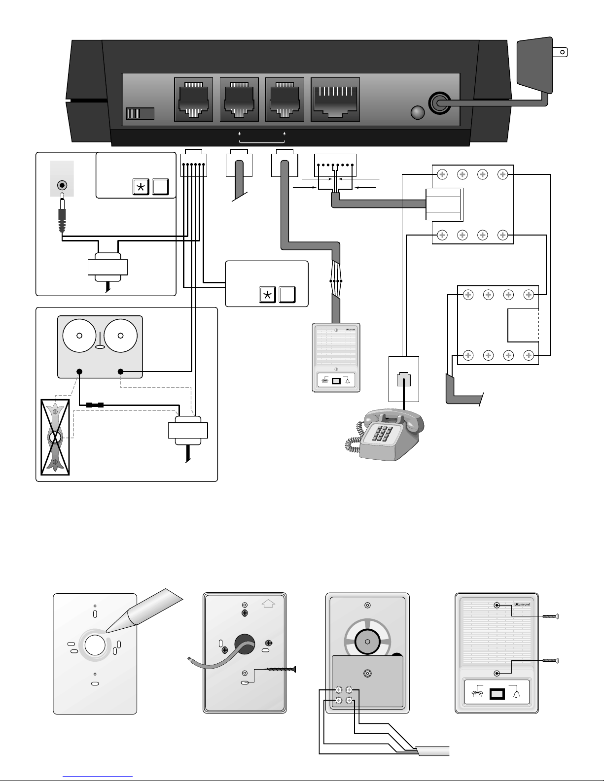
5. Connections . . . . . . . . . . . . . . . . . . . . . . . . . . . . . . . . . 4
6. Installation . . . . . . . . . . . . . . . . . . . . . . . . . . . . . . . . . . 4
7. Operation . . . . . . . . . . . . . . . . . . . . . . . . . . . . . . . . . . . 6
8. Programming . . . . . . . . . . . . . . . . . . . . . . . . . . . . . . . . 6
9. Trouble Shooting . . . . . . . . . . . . . . . . . . . . . . . . . . . . . . 7
10. Warranty . . . . . . . . . . . . . . . . . . . . . . . . . . . . . . . . . . . 7
2

2. INTRODUCTION
Congratulations on your purchase of the DTI-1 Doorbell Telephone Interface, a system that offers enhanced
security while providing unparalleled convenience. The system can be used with or without a doorbell.
Operation of this unit is subject to the following conditions:
1. This device may not cause harmful interference.
2. This device may accept any interference including interference that may cause undesired operation.
Complies with Part 68, FCC Rules FCC REG NO. 5ERCAN-31264-OT-N REN: 0.8B (DOC/CSA/NTRL/C approved)
3. PARTS LIST
The DTI-1 Doorbell Telephone Interface system is shipped from the factory with the following components:
1. DTI-1 Doorbell Telephone Interface control unit enclosed in plastic housing
2. TDB-1 TeleDoorBell speaker unit with wall mounting plate
3. CSA/UL approved class 2 Power Supply, Input 120VAC, 60Hz, Output 16Vac 250 mA. Note: the system will
also work with a class 2 Power Supply Input 120VAC, Output 16-24Vdc 350 mA. Please make sure that the
output does not exceed 24 VDC or serious damage may occur.
4. Two modular RJ-11 Male open-ended patch cord. Used to splice and connect door speaker unit, door strike
and doorbell, to the DTI-1 system unit.
5. RJ-45 8 pin male to male modular patch cord.
6. Four (4) #6 wood screws for mounting.
7. Two (2) white painted oval-head machine screws.
8. RJ31X (CA38A) Data Jack included.
4. FEATURES
The DTI-1 Doorbell Telephone Interface is a telephone based doorbell system that provides the system user with the
capability of communicating with a door speaker from any installed telephone set, including cordless. Unmatched
in convenience, this unique new product provides the following features:
1. System will work as a replacement or in parallel with any standard doorbell.
2. Supports speakerphone quality conversation between the telephone and the door speaker.
3. Unique telephone ringing when door speaker button is depressed.
4. Allows homeowner to activate the door speaker(s) by entering a unique touch-tone code from any telephone.
5. Toll Restriction, 1+ long distance and 011 international, user selectable.
6. Relay closure to ring doorbell or a number of other devices.
7. Can be set to ring doorbell only.
8. RJ31X (CA38A) Data Jack.
9. Door speaker has LEDs for constant illumination.
10. The system gives a user two minutes to access door following the depression of the door speaker button.
11. If the door speaker button is depressed, when the telephone is in use on an outside call, the user hears a beep
tone to alert that there is a visitor at the door. The user can then put the telephone call on hold and connect to
the door speaker. Alternatively, a user can hang up on the telephone call and then pick up the handset and they
will be connected to the door speaker.
12. A DTMF code selection (dialed from any connected telephone) allows the system user to access the door
speaker outside of the two-minute window.
13. Relay closure activated by DTMF digit *8, provides 6-second door strike contact operation.
(Normally Open NO).
14. Automatic relay closure for six (6) seconds upon door button depression or telephone line ringing. Used to
mute sound system
15. Password protection for programming which user can change to a personal 3-digit DTMF code.
16. Progress tones to guide user while programming.
3

5. CONNECTIONS
1. Telephone Ringer Selector Switch – This switch enables/disables ringing of the telephones. When positioned
to the left, this switch enables ringing of the telephones.
2. Doorbell/Door Strike/Sound system mute (Relay Contacts) Connecting Jack – The center two pins connect to
the doorbell button and will ring an existing or new doorbell. The adjacent pair will provide a six second
closure upon door button depression or incoming telephone line ringing (this is used to mute a sound sys-
tem). The adjacent pair offers a user selectable (*8) relay closure than can be used to operate a door strike or
other relay controlled ancillary devices.
3. Door Speaker Connecting Jacks – Each of these jacks enables a connection to door speaker for communicat-
ing to a door speaker.
4. Telephone Line (In & Out) Connecting Jack – This jack provides connection to the incoming telephone line
on the inner pair and connection to household telephone(s) on the outer pair.
5. Power Status LED – When "ON," this lamp indicates the presence of power to the unit, when "OFF," it indi-
cates the absence of power to the unit.
6. Power Supply Jack – This jack is the connecting point for AC power supply to the unit; The supply is typically
16 Vac at a minimum of 250 mA, but can be as high as 20Vac, which will provide greater ringing power to
the telephones. Can also use a 16-24 VDC supply. (Note: Do not exceed 24 VDC or serious damage can
occur to the controller unit)
CAUTION: For added protection we strongly recommend you use surge protectors on both your power sup-
ply and on the C/O line (phone line) to protect against lightning and other energy surges.
6. INSTALLATION
To complete the installation the installer must supply the following:
• RJ31X/CA38A disconnect and bypass jack. This will provide a bypass capability whereby the telephone line
continues to work if the DTI-1 needs to be removed from the telephone line. Note: If installation is done at a
location that has an existing alarm jack (RJ31X/CA38A) then ensure that the alarm is installed before the DTI-
1 RJ31X/CA38A jack. Otherwise, the alarm system may not have disconnect priority.
• Two plastic wall anchors to mount the TDB-1 door speaker unit near a point of entry.
Figure 1 shows the detail of the connectors located on the front of the unit. Figure 2 shows interconnection of the
DTI-1 with other parts that form the system.
Installation of the system requires that the installer install a 4-conductor wire (24 AWG) be installed from the
location of the door speaker unit to the location of the system control unit. It is recommended that the system
control unit be installed near the point-of-entry of the customer's main telephone line. Please ensure that ade-
quate AC power is available in the general vicinity.
1. First install the Back Mounting Plate. We recommend that you use a silicon sealer to protect the wiring. Apply
a ring of silicon around the round hole on the rear of the mounting plate as shown in figure 3.
2. Thread 4 conductor wire through the hole in the Back Mounting Plate.
3. Use the included 1/2” dry wall screws to mount the back plate to the wall. Make sure the the silicon makes a
seal between the wall and the plate. Drive screws through the oblong screw holes and into the wall as
shown in figure 4 but do not tighten screws down all the way. Once all screws are driven, adjust plate to
make sure it is level. Once the plate is level, tighten the screws.
4. Connect the four wires to the wiring posts on the rear of the TDB-1 as shown in figure 5.
4
1 2 3 4 5 6
fig 1

5
Telephone
Ring On/Off Remote
Trigger Tele-
DoorBell Telephone
Line (In & Out) Power Plug
16VAC
21
Existing
doorbell
transformer
Existing doorbell switch
(to be removed)
Disconnect switch and
connect wires together
Wire is reconnected
to the TDB-1
120V AC
already
connected
RJ11 Modular Wire
(Supplied with Unit)
RJ45 Modular Wire
(Supplied with Unit)
16V AC
OUTPUT
22 Gauge
4 Conductor wire
Max length 250 ft.
(not supplied)
Note: Center pair are phone
line into DTI-1. Outer pair
are to the phones
TeleDoorBell™
TDB-1
To second TDB-1
or other device such
as the TPM-1 paging
module
OUT IN
OUT IN
RJ31X
(CA38A)
Data Jack
(supplied)
Phone
Jack
OUTIN
OUTIN
RJ31X
(CA38A)
Alarm Jack
(not supplied)
Alarm jack connection
only if alarm monitored
TELCO in line
from phone company
Power Supply
(ex. 12VDC)
MUTE
INPUT
Used to mute a sound
system such as a Russound
CA4.4pi or PR-4Z 5
PRESS
8
PRESS
Used to activate devices
such as remote door unlock
and gate openers
+–
BLACK
GREEN
RED
YELLOW
fig 2
fig 5 fig 6
SILICONE
fig 3
UP
fig 4
GREEN
BLACK
RED
YELLOW
TeleDoorBell™
5. Attach front of TDB-1 to Back Mounting Plate (already anchored on the wall) by screwing in the two white
oval-head machine screws (included) as shown in figure 6.
NOTE: The DTI will support an optional second door station. In this configuration both stations are active
when using the DTI. In some cases high ambient noise may cause one speaker to drown out the second. This
can be corrected by repositioning the affected speaker or by installing a second control unit in series providing
independent control of the speakers.

4. While on a regular telephone conversation, depression of the door speaker button will cause a unique call
indication tone to be applied over the conversation. The door bell will also ring, if enabled. *4can be
used to put the telephone call on hold and connect to the door speaker. Using *4again will return to the
telephone call. This hold feature can be used only once per door speaker button depression. Alternatively, a
user can hang up the active conversation and then pick up the receiver and a connection will occur with the
door speaker. A user has two minutes to do this, otherwise, *#*needs to be used. If a door strike sys-
tem has been installed, to automatically open a door or a gate, a user can activate it by depressing *8on
the keypad while connected to the speaker. This will cause a five second contact closure and open the door
or gate automatically.
8. PROGRAMMING
NOTE: If the power goes out, the DTI-1 will lose its
programming and return to factory setting, including password.
To prevent loss of programming, use of a UPS power device
is recommended.
7. OPERATION
1. If your doorbell rings or you hear the unique DTI-1 ring signal, pick up any telephone in the house within
two minutes. You can now talk to the person at the entrance.
2. If two minutes has expired, then pick up any telephone and press *#*on the touch tone keypad on
your telephone. This will connect you to the door speaker.
NOTE: Using *#*can be done at times when no one has depressed the door speaker button and pro-
vides the user with a monitor function.
3. The DTI-1 provides a six second contact closure when the door button is depressed or when the telephone
line rings. This provides a mute function if connected to Russound Multi-Zone controller such as the
CA4.4pi, PR-4Z and CP 4.6.
6
In the following, an acknowl-
edgement of three beeps will
indicate that the dialing
sequence is disabled, two
beeps will indicate the dialing
sequence is enabled.
Pick up handset.
Press *#*.
Press *7.
Listen for 2 beeps.
Enter your passcode.
Default is 111.
Long Distance Restrictions
Disable/Enable 1+ dialing **1.
Disable/Enable 011+ dialing 011
.
Change Passcode
Enter Passcode Mode 727
.
Listen for 2 beeps
Enter New Passcode ???
.
Action Result
Door box button depressed and call answered after
six seconds but within two minutes
Mute relay releases after six seconds following but-
ton depression. User will be connected to door box
automatically. User can trigger the mute function by
depressing *5. This will provide a six second mute
pulse.
Telephone line ringing –User does not answer call Mute relay closes during the time the line rings and
six seconds beyond the last ring.
Telephone line ringing –User answers call Mute relay will release six seconds after call is
answered.
Door box button depressed and call answered with-
in six seconds
Relay closes for six seconds to provide mute func-
tion. The mute relay will stay closed for duration of
conversation.

9. TROUBLE SHOOTING
10. WARRANTY
The Russound DTI-1 and TDB-1 are fully guaranteed for One (1) year from the date of purchase against all defects in materials and
workmanship. During this period Russound will replace any defective parts and correct any defect in workmanship without charge for
either parts or labor. For this warranty to apply, the unit must be installed and used according to its written instructions. If service is nec-
essary, it must be performed by Russound. The unit must be returned to Russound at the owner’s expense and with prior written permis-
sion. Accidental damage and shipping damage are not considered defects under the terms of the warranty. Russound assumes no
responsibility for defects resulting from abuse or servicing performed by an agency or person not specifically authorized in writing by
Russound. Damage to or destruction of components due to improper use voids the warranty. In these cases the repair will be made at
the owner’s expense. To return for repairs, the unit must be shipped to Russound at the owner’s expense, along with a note explaining
the nature of the service required. Be sure to pack in a corrugated container with at least 3 inches of resilient material to protect the unit
from damage in transit.
7
Solution
1. Check your AC and power adapter, confirm LED Power
Indicator is ON.
2. Check the power connection into the unit.
1.
Are your phones wired into the RJ31X/CA38A data jack
(output)? To test connection, remove the RJ45 wire from
the RJ31X/CA38A data jack which bypasses the DTI-1 and
connect the phones directly to the main incoming line.
2. Check for any breaks in the RJ45 wire.
1. The green and yellow wires may be reversed, either at
the speaker or at the controller.
2. The red and black wires may be reversed, either ar the
speaker or at the controller.
1. Your ringer switch located at the front of the controller
may be set to the OFF position.
2. The yellow wire is not properly connected to either the
speaker or the controller section of the speaker.
3. One of the phones may be causing too much of a load;
unplug all phones and begin testing with one phone at a
time untill the defective phone is found.
Reverse the In and Out on the RJ45 data jack.
1. You have attached the phones on the premises in
parallel with the DTI-1 across your outgoing phone line
2. Your telephones may not be touchtone compatable. Or
the touchtone switch is in the off postition.
3. Please check the connection of the yellow wire at both
ends.
4. If you have more than one telephone line you may have
wired thewrong line to the controller.
The unit has been designed to go a maximum of 250 ft.
with a 22 gauge wire. A possible solution to gain an
additional 100ft. would be to increase the gauge thick-
ness (18 or 16). You can also double up the red and
black wires to give it the added gauge.
1. If you have more than one telephone line you may have
wired the wrong line to the controller.
2. Check the connection of the yellow wire at both ends.
Problem
Controller not responding.
Your phones don’t work.
When a door speaker is pressed, phones ring but
you have no audio communications to the door.
The DTI-1 Doorbell Telephone Interface works but
the phones don’t ring when the speaker button is
pressed.
You have a dial tone feedback at the speaker when
door speaker button is pressed.
When pressing *#*(for monitoring the door)
you get an operator recording (eg. “this is an
invalid number”) and you have no communication
to the speaker.
On a gate installation, you have no audio
communication to the speaker.
Telephone does not ring when door button is
pressed.

8
5 Forbes Rd. Newmarket, NH 03857, USA
☎ 603.659.5170 •Fax 603.659.5388
e-mail: [email protected]
Come visit us at:
Table of contents
Other Russound Accessories manuals
Popular Accessories manuals by other brands

Hydac
Hydac CS 2000 series Operating and maintenance manual

PowerTraveller
PowerTraveller SOLARMONKEY ADVENTURER user guide

ASL INTERCOM
ASL INTERCOM PS 260T user manual

Orion
Orion ASTROVIEW 9822 instruction manual

Emmaljunga
Emmaljunga NXT SEAT UNIT FLAT instruction manual

Makita
Makita CJ101D instruction manual