manuals.online logo
Brands
  1. Home
  2. •
  3. Brands
  4. •
  5. ipf electronic
  6. •
  7. Accessories
  8. •
  9. ipf electronic UT300027 User manual

ipf electronic UT300027 User manual

Ultrasonic Distance Sensor
Ultraschall Abstandssensor
Capteurs Ultrasoniques
UT300027
*TEACH IN *ANALOGUE AND 2SWITCHING OUTPUTS *
ANALOGAUSGANG UND 2SCHALTAUSGÄNGE *
SORTIES ANALOGIQUE ET 2SORTIES A SEUIL
Detection Range/ Erfassungsbereich/Plage
de détection:
Sensors/ Sensoren/ Capteurs 5 pin connector : included / beinhaltet / comprend
Technical Data / Technische Daten/ Données techniques
Specifications at 25° typically/ typisch/ typiques
Detection range Erfassungsbereich Portée 150 ... 1500 mm
Beam angle(°) Schallkegelöffnung (°) Angle du faisceau (°) 8
Carrier frequency Trägerfrequenz Fréquence porteuse 200 kHz
Temperature compensat. Temperaturkompensation Compensat. en temp. Yes/Ja/oui
Analogue output Analogausgänge Sortie analogique 0 … 10 V
Repeatability Wiederholgenauigkeit Répétabilité ±2 mm ±0.4%
Response time
Target speed <1m/s
Stepp response
Ansprechzeit
Ojektgeschwindigkeit <1m/s
Sprungantwort
Temps de réponse
Velocité du cible <1m/s
Présence / absence cible 60 ms
300 ms
Linearity Linearitätsfehler Linéarité ±0.5% / 3mm
Output adjustment Einstellung des Ausgangs Réglage de la sortie Teach In
Switching outputs Schaltausgänge Sorties à seuils 2 NO/ NC ; PNP
Repeatability Wiederholgenauigkeit Répétabilité ±2 mm ±0.4%
Switching frequency Schaltfrequenz Fréquence commutat. 1 Hz
Hysteresis Hysterese Hystérésis 1 % / 2mm
Output circuit Ausgangsschaltung Circuit de sortie Open collector 100 mA
Set point adjustment Schaltpunkteinstellung Réglage points consig. Teach In
NO or NC NO oder NC NO ou NC Teach In
Set point indicator Schaltpunktanzeige Indication de l’etat seuil 2 LED
Alignment LED Ausrichthilfe LED DEL à l’alignement Yes/ Ja/ Oui
Temperature range Temperaturbereich Température service -15-+70 °C
Storage temperature range Lager Temperatur Température stockage -25-+85 °C
Supply voltage Versorgungsspannung Tension d’alim. 19-30 V DC
Current consumption without load Stromverbrauch ohne Last Courant consommé sans charge <=25 mA
Circuit protection Schutz gegen Protections de circuit
Reverse polarity Verpolung Inversion de polarité Yes
Voltage spikes on supply and output
lines Spannungsspitzen in
Versorgungsleitungen Transitoires sur alimentation
et sortie Yes
Short circuited switching output Kurzschluß des Ausgangs Courts-circuits sur sortie à seuils Yes
Sealing IP Schutzart IP Degré de protection IP 67
Housing Gehäuse Boîtier Plastic/ Kunststoff/ Plastique
!!! WARNING !!!
PERSANAL INJURI
DO NOT USE these products as safety or
emergency stop devices, or in any other
application where failure of the product could
result in personal injury.
Failure to comply with these instructions could
result in death or serious injury.
!!! WARNUNG !!!
PERSONENSCHADEN
Diese Produkte dürfen weder als Sicherheits- oder Not-
Abschaltgeräte noch in anderen Anwendungen, bei denen
ein Fehler an diesem Produkt zu Personenschaden führen
könnte, eingesetzt werden.
Missachtung dieser Anweisungen kann zu schweren
Verletzungen oder zum Tod führen.
!!! ATTENTION !!!
BLESSURES COPORELLES
NE PAS UTILISER ces produits en tant que dispositifs
d’arrêt d’urgence ou de sécurité, ni dans aucune autre
application où la défaillance du produit pourrait entraîner
des blessures corporelles.
L’inobservation de ces instructions peut entraîner la
mort ou de graves blessures.
0 150 1500 mm
+ 300
-300
mm
Guaranteed detection of a target 100x100 mm²
Sichere Erfassung eines Objektes 100x100 mm²
Détection assurée d’une cible de 100x100 mm²
Possible detection of a large target
Mögliche Erfassung eines großen Objektes
Détection possible d’une large cible
MANUAL •Subject to alteration! Version: July 2004
ipf electronic gmbh
•Rosmarter Allee 14 •58762 Altena
│
Tel +49 2351 9365-0 •Fax +49 2351 9365-19
│
[email protected] •www.ipf-electronic.com 1
Key/Taster
P1 LED SP1 0 V
P2 LED SP2 10 V
Echo LED Echo
Wiring
Pin Function
1 24 Vdc
3 0 V GND
2 SP2
4 SP1
5 0 … 10 V View to solder pins of
female connector/ Blick
auf Lötkontakte Kabel-
buchse/ Vue sur les pins à
soudée du connecteur
cable Dimensions/Abmessungen/Dimensions
Analogue output adjustment
P1 and P2 defines the analogue output
slope. P1 determines the 0 V position and
P2 the 10 V position.
Positive slope: P1 < P2
Negative slope: P2 < P1
Switching output characteristics
NO/NC
P1 and P2 also determines the position of
the set points. Is during teach in of the set
point the corresponding LED on, then the
switching output has NO characteristics, is
it off, then it has NC characteristics.
Analoge Kennlinie
Mit P1 und P2 wird der Arbeitsbereich der analogen
Kennlinie festgelegt: P1 bestimmt die Position an
der die Kennlinie den Wert OV annimmt, P2
bestimmt die Position 10 V.
Positive Kennlinie: P1 < P2
Negative Kennlinie: P2 < P1
Schaltausgänge Charakteristik NO/NC
P1 und P2 legen auch die Positionen der Schalt-
punkte fest. Ist beim Einlernen des Schaltpunktes die
entsprechende LED an, so hat der Schaltpunkt NO
Charakteristik, ist sie aus, so ist die Charakteristik
NC.
Sortie analogique
P1 et P2 definissant la position de la sortie
analogique. P1 le point 0V,
P2 le point 10V.
Charactéristique positive: P1 < P2
Charactéristique négative: P1 > P2
Interrupteur NO / NC
P1 et P2 définissant aussi les positions
seuil. Si DEL est allumer pendant
memorisation la sortie à seuil est
normallement ouvert, si DEL n’est pas
allumer elle est normalement fermée.
Teach in procedure /
Einlernvorgang /
Procédure de mis en mémoire
Normal function:
Echo LED on, when echo received (alignment
LED). LED2 P1 and P2 are indicating status
of the switching outputs
Normale Funktion :
Echo LED an, wenn Echo empfangen wird
(Ausrichthilfe).LEDs P1 und P2 zeigen
Schaltzustand SP1 und SP2.
Fonction normale:
DEL Echo allumé si echo recu (alignement)
DEL P1 et P2 montres l’état des sorties à
seuil.
Teach In modus P1 (Position 0V and SP1)
Press key around 8 sec until LEDs P1 and
Echo start blinking ~2Hz.
Release key: Now sensor is in Teach In mode
for P1:
LED P1 is blinking ~1Hz, Echo LED
normal function (alignment LED)
Within 1 min. P1 has to be programmed!
Place target at new position P1.
Press and release key, P1 is programmed.
Sensor returns into normal function with
new value for P1.
Teach In Modus P1 (Position 0V und SP1)
Taster ca. 8 sec. drücken bis LEDs P1 und
Echo anfangen mit ~2Hz zu blinken.
Taster loslassen: jetzt ist Sensor im Tech In
Modus für P1:
LED P1 blinkt mit ~ 1Hz; Echo LED
normale Funktion (Ausrichthilfe)
Innerhalb von 1 min. muß P1 eingelernt
werden!
Objekt an neue Position P1 bringen
Taster drücken und loslassen: P1 ist eingelernt.
Sensor arbeitet jetzt in normaler Funktion
mit neuem eingestellten Wert für P1.
Teach In mode P1 (Position 0V et SP1)
Appuyer bouton environ 8 sec. jusque DELs
P1 et Echo clignotes ~2Hz.
Relâcher le bouton: capteur est en mode
‘programmation P1:
DEL P1 clignote ~1 Hz; DEL echo
fonction normale (alignement).
Pendant 1 min. P1 doit être mémorisée !
Positionnez l’objet à position nouveau de P1.
Pressez et laissez bouton: P1 est mémorisee.
Capteur travaille en fonction normale avec
nouveau valeur pour P1.
Teach In modus P1 (Position 10V and SP2)
Press key around 13 sec until LEDs P2 and
Echo start blinking ~2Hz.
After 8 sec. start LEDs P1 and Echo
blinking, then after additional 5 sec. LEDs
P2 and Echo are blinking with 2 Hz.
Release key: Now sensor is in Teach In mode
for P2:
LED P1 is blinking ~1Hz, Echo LED
normal function(alignment LED)
Within 1 min. P1 has to be programmed!
Place target to new position P2
Press and release key, P2 is programmed.
Sensor returns into normal function with new
value for P2.
Teach In Modus P2 (Position 10V und SP2)
Taster ca. 13 sec.drücken bis LED P2 und
Echo LED anfangen mit ~2Hz zu blinken.
Nach 8 sec. fangen LED P1 und Echo LED
an zu blinken, nach weiteren 5 sec. blinkt
dann LED P2 und Echo LED mit ~2Hz.
Taster loslassen: jetzt ist Sensor im Tech In
Modus für P2:
LED P2 blinkt mit ~ 1Hz; Echo LED
normale Funktion (Ausrichthilfe).
Innerhalb von 1 min muß jetzt P2 eingelernt
werden!
Objekt an neue Position P2 bringen.
Taster drücken und loslassen: P2 ist eingelernt
Sensor arbeitet jetzt in normaler Funktion
mit neuem eingestellten Wert für P2.
Teach In mode P2 (Position 10V et SP2)
Appuyer bouton environ 13 sec. jusque DELs
P2 et Echo clignotes ~2Hz.
Après 8 sec. DELs P1 et Echo commen-
ces à clignotés, après 5 sec. DELs P2 et
Echo clignotes.
Relâcher le bouton: capteur est en mode
programmation P2:
DEL P2 clignote ~1 Hz; DEL echo
fonction normale (alignement).
Pendant 1 min. P2 doit être mémorisée !
Mettre en place la cible au point
correspondant à P2.
Appuyer une fois sur le bouton et relâcher. P1
est programmé..
Capteur travaille en fonction normale avec
nouveau valeur pour P2.
Assessories/Zubehör/Assessoires
AU000003 Beam deflector/ Umlenkwinkel/ Deflecteur de faisceau
AU000004 ‘’ focusing/ fokussierend/ focalisant
P1 P2
10
0V P2 P1
10
0V
MANUAL •Subject to alteration! Version: July 2004
ipf electronic gmbh
•Rosmarter Allee 14 •58762 Altena
│
Tel +49 2351 9365-0 •Fax +49 2351 9365-19
│
[email protected] •www.ipf-electronic.com 2

Other ipf electronic Accessories manuals

ipf electronic OT330571 User manual

ipf electronic

ipf electronic OT330571 User manual

ipf electronic OT059170 User manual

ipf electronic

ipf electronic OT059170 User manual

ipf electronic MW10015 Series User manual

ipf electronic

ipf electronic MW10015 Series User manual

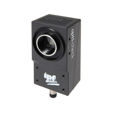
ipf electronic opti-check OC5396 Series User manual

ipf electronic

ipf electronic opti-check OC5396 Series User manual

ipf electronic OT450521 User manual

ipf electronic

ipf electronic OT450521 User manual

ipf electronic OTR49175 User manual

ipf electronic

ipf electronic OTR49175 User manual

ipf electronic OTQ80576 User manual

ipf electronic

ipf electronic OTQ80576 User manual

ipf electronic UT360321 User manual

ipf electronic

ipf electronic UT360321 User manual

ipf electronic OT05E244 User manual

ipf electronic

ipf electronic OT05E244 User manual

ipf electronic UT309023 User manual

ipf electronic

ipf electronic UT309023 User manual

ipf electronic PY740020 User manual

ipf electronic

ipf electronic PY740020 User manual

ipf electronic UT189020 User manual

ipf electronic

ipf electronic UT189020 User manual

ipf electronic PT65 Series User manual

ipf electronic

ipf electronic PT65 Series User manual

ipf electronic ON330571 User manual

ipf electronic

ipf electronic ON330571 User manual

ipf electronic PRQ80376 User manual

ipf electronic

ipf electronic PRQ80376 User manual

ipf electronic OTR49174 User manual

ipf electronic

ipf electronic OTR49174 User manual

ipf electronic DW35312 Series User manual

ipf electronic

ipf electronic DW35312 Series User manual

ipf electronic RO570900 User manual

ipf electronic

ipf electronic RO570900 User manual

ipf electronic OTR49176 User manual

ipf electronic

ipf electronic OTR49176 User manual

ipf electronic ON430570 User manual

ipf electronic

ipf electronic ON430570 User manual

ipf electronic PT230020 User manual

ipf electronic

ipf electronic PT230020 User manual

ipf electronic OR150400 User manual

ipf electronic

ipf electronic OR150400 User manual

ipf electronic UT139570 User manual

ipf electronic

ipf electronic UT139570 User manual

ipf electronic UT300025 User manual

ipf electronic

ipf electronic UT300025 User manual

Popular Accessories manuals by other brands

TP-Link TL-PB15600 quick start guide

TP-Link

TP-Link TL-PB15600 quick start guide

Anker Powercore+ MINI Welcome guide

Anker

Anker Powercore+ MINI Welcome guide

Reflex Fillguard Instructions for use

Reflex

Reflex Fillguard Instructions for use

Cedes TLS 600 Quick guide manual

Cedes

Cedes TLS 600 Quick guide manual

BFT PROX installation manual

BFT

BFT PROX installation manual

Baumer OADM 12I6460/S35A manual

Baumer

Baumer OADM 12I6460/S35A manual

nodon SWO-2-1-00 user guide

nodon

nodon SWO-2-1-00 user guide

MOB MO8113 user manual

MOB

MOB MO8113 user manual

Whadda WPSE342 user manual

Whadda

Whadda WPSE342 user manual

Kopp 2931.1302.9 instruction manual

Kopp

Kopp 2931.1302.9 instruction manual

NETGEAR AXM763 - ProSafe 10 Gigabit LRM installation guide

NETGEAR

NETGEAR AXM763 - ProSafe 10 Gigabit LRM installation guide

3D Fun Printz Universal Pen Holder quick start guide

3D Fun Printz

3D Fun Printz Universal Pen Holder quick start guide

Hytronik HIM39/RF Installation and instruction manual

Hytronik

Hytronik HIM39/RF Installation and instruction manual

ITS Telecom WaterFeature8 A Series instruction manual

ITS Telecom

ITS Telecom WaterFeature8 A Series instruction manual

YOKOGAWA CT2000A user manual

YOKOGAWA

YOKOGAWA CT2000A user manual

Mophie powerstation mini user manual

Mophie

Mophie powerstation mini user manual

Sharper Image 204416 user guide

Sharper Image

Sharper Image 204416 user guide

LaserLiner LaserRange-Master Gi7 Pro manual

LaserLiner

LaserLiner LaserRange-Master Gi7 Pro manual

manuals.online logo
manuals.online logoBrands
  • About & Mission
  • Contact us
  • Privacy Policy
  • Terms and Conditions

Copyright 2025 Manuals.Online. All Rights Reserved.