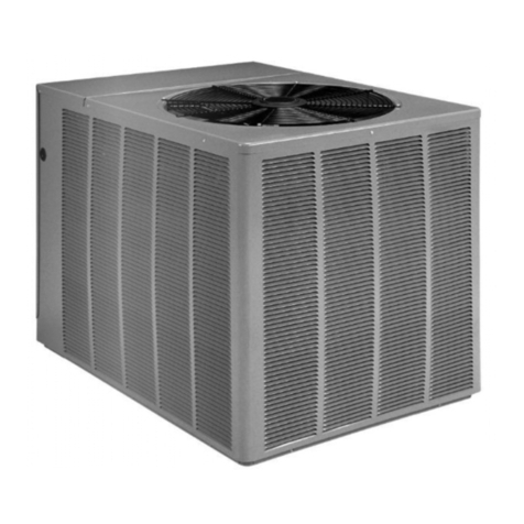
Ruud RHPBZR Series User manual

INSTALLATION INSTRUCTIONS
PACKAGED HEAT PUMPS FEATURING
EARTH-FRIENDLY R-410A REFRIGERANT
RHPBZR (2-5 TONS) 13.4 SEER2
92-108851-01-00

2
ACCREDITED
,62
THESE INSTRUCTIONS ARE INTENDED AS AN AID TO
QUALIFIED, LICENSED SERVICE PERSONNEL FOR
PROPER INSTALLATION, ADJUSTMENT AND OPERATION
OF THIS UNIT. READ THESE INSTRUCTIONS THOROUGHLY
BEFORE ATTEMPTING INSTALLATION OR OPERATION.
FAILURE TO FOLLOW THESE INSTRUCTIONS MAY RESULT
IN IMPROPER INSTALLATION, ADJUSTMENT, SERVICE OR
MAINTENANCE POSSIBLY RESULTING IN FIRE, ELECTRICAL
SHOCK, PROPERTY DAMAGE, PERSONAL INJURY OR DEATH.
WARNING
!
!
TABLE OF CONTENTS
I. Safety Information ......................................... 3
II. Breakdown Page ........................................... 4
III. Introduction .................................................. 5
IV. Agency Performance Audit And Efciency
Testing Notice .................................................... 5
V. Importance Of A Quality Installation ................ 5
VI. Importance Of Air Flow And Setup ................. 5
VII. Checking Product And Inspection ............... 5
VIII. Installation .................................................. 8
A. General ................................................... 8
B. Outside Slab Installation ......................... 8
C. Clearances .............................................. 8
D. Rooftop Installation ................................. 8
IX. Ductwork ...................... 10
X. Filters .................. 10
XI.Condensate Drain ........................................ 10
XII.Condensate Drain, Outdoor Coil ................ 10
XIII. Electrical Wiring ........................................ 10
A. Power Wiring ......................................... 10
B. Power Wiring And Electric Heater Kit
Instructions ................................................. 11
C. Control Wiring (Class Ii) .......................... 11
D. Internal Wiring ....................................... 11
E. Grounding .............................................. 11
F. Thermostat ............................................
XIV. Indoor Air Flow Data .................................. 12
XV. Pre-Start Check ......................................... 12
XVI. Startup ..................................................... 12
XVII. Operation ........................ 12
XVIII. Auxiliary Heat ......................................... 12
XIX. Demand Defrost Control And High/Low
Pressure Controls ............................................ 13
XX. General Data - RHPB ................................. 15
XXI. Electrical Data ........................................... 17
XXII. Airow Performance ............................... 18
XXIII. Heater Kit Characterstics ........................ 19
XXIV. Wiring Diagrams .................................... 19

3
WARNING
PROPOSITION 65: THIS APPLIANCE CONTAINS FIBER-
GLASS INSULATION. RESPIRABLE PARTICLES OF
FIBERGLASS ARE KNOWN TO THE STATE OF CALI-
FORNIA TO CAUSE CANCER.
!
WARNING
THE MANUFACTURER’S WARRANTY DOES NOT
COVER ANY DAMAGE OR DEFECT TO THE HEAT
PUMP CAUSED BY THE ATTACHMENT OR USE OF
ANY COMPONENTS, ACCESSORIES OR DEVICES
(OTHER THAN THOSE AUTHORIZED BY THE MANU-
FACTURER) INTO, ONTO OR IN CONJUNCTION WITH
THE HEAT PUMP. YOU SHOULD BE AWARE THAT
THE USE OF UNAUTHORIZED COMPONENTS, AC-
CESSORIES OR DEVICES MAY ADVERSELY AFFECT
THE OPERATION OF THE HEAT PUMP AND MAY ALSO
ENDANGER LIFE AND PROPERTY. THE MANUFAC-
TURER DISCLAIMS ANY RESPONSIBILITY FOR SUCH
LOSS OR INJURY RESULTING FROM THE USE OF
SUCH UNAUTHORIZED COMPONENTS, ACCESSO-
RIES OR DEVICES.
!
WARNING
DISCONNECT ALL POWER TO THE UNIT BEFORE
STARTING MAINTENANCE. FAILURE TO DO SO
CAN RESULT IN SEVERE ELECTRICAL SHOCK OR
DEATH.
!
WARNING
DO NOT, UNDER ANY CIRCUMSTANCES, CONNECT
RETURN DUCTWORK TO ANY OTHER HEAT PRO-
DUCING DEVICE SUCH AS A FIREPLACE INSERT,
STOVE, ETC. UNAUTHORIZED USE OF SUCH DE-
VICES MAY RESULT IN FIRE, CARBON MONOXIDE
POISONING, EXPLOSION, PROPERTY DAMAGE, SE-
VERE PERSONAL INJURY OR DEATH.
!
WARNING
TURN OFF ELECTRIC POWER AT THE FUSE BOX OR
SERVICE PANEL BEFORE MAKING ANY ELECTRICAL
CONNECTIONS.
ALSO, THE GROUND CONNECTION MUST BE
COMPLETED BEFORE MAKING LINE VOLTAGE
CONNECTIONS. FAILURE TO DO SO CAN RESULT IN
ELECTRICAL SHOCK, SEVERE PERSONAL INJURY
OR DEATH.
!
WARNING
THE UNIT MUST BE PERMANENTLY GROUNDED.
A GROUNDING LUG IS PROVIDED. FAILURE TO
GROUND THIS UNIT CAN RESULT IN FIRE OR ELEC-
TRICAL SHOCK CAUSING PROPERTY DAMAGE, SE-
VERE PERSONAL INJURY OR DEATH.
!
WARNING
ONLY ELECTRIC HEATER KITS SUPPLIED BY THIS
MANUFACTURER AS DESCRIBED IN THIS PUBLICA-
TION HAVE BEEN DESIGNED, TESTED, AND EVAL-
UATED BY A NATIONALLY RECOGNIZED SAFETY
TESTING AGENCY FOR USE WITH THIS UNIT. USE
OF ANY OTHER MANUFACTURED ELECTRIC HEAT-
ERS INSTALLED WITHIN THIS UNIT MAY CAUSE
HAZARDOUS CONDITIONS RESULTING IN PROP-
ERTY DAMAGE, FIRE, BODILY INJURY OR DEATH.
!
I. SAFETY INFORMATION
WARNING
PROPOSITION 65: THIS APPLIANCE CONTAINS FI-
BERGLASS INSULATION. RESPIRABLE PARTICLES
OF FIBERGLASS ARE KNOWN TO THE STATE OF
CALIFORNIA TO CAUSE CANCER.
!
For purposes of verifying or testing efciency ratings, the test procedure in Title 10 Part 431 Appendix A
to Subpart F (Uniform Test Method for Measuring the Energy Consumption of Small Large and Very Large
Commercial Packaged Air Conditioning and Heating Equipment), Title 10 Part 431.76 Subpart D (Uniform Test
Method for Measuring Energy Consumption of Commercial Warm Air Furnaces), and the clarifying provisions
provided in the AHRI Operations Manuals for Unitary Large Equipment 340/360, 365 and Commercial Furnaces
that were applicable at the date of manufacture should be used for test set up and performance.
EFFICIENCY TESTING NOTICE

4
R HP B ZR 036 A J T 10 1 N A X X X
Factory Installed Options
(See Spec Sheet)
Minor Series
A = 1st Variation
Control
N = Non Communicating
Heat Configuration
1 = Single Stage
Heating Capacity
00 = No Heat
05 = 05 kW
07 = 07 kW
10 = 10 kW
15 = 15 kW
20 = 20kW
Drive Package
T = Constant Torque
Voltage
J=208-230V—1PH—60 Hz
Major Series
A = 1st Variation
Cooling Capacity (BTUH) [kW]
024 = 24,000 [7.03]
030 = 30,000 [8.79]
036 = 36,000 [10.55]
042 = 42,000 [12.31]
048 = 48,000 [14.07]
060 = 60,000 [17.59]
Series
ZR = Base Tier
(13.4 SEER2)
Cabinet Type
B=Dedicated Horizontal
Unit Type
HP = Packaged Heat Pump
Tradebrand
R=Rheem
II. BREAKDOWN PAGE

5
III. INTRODUCTION
This booklet contains the installation and operating instructions for
your packaged heat pump unit. There are some precautions that
should be taken to ensure proper operation. Improper installation
can result in unsatisfactory operation or dangerous conditions.
Read this booklet and any instructions packaged with sep-
arate equipment required to make up the system prior to in-
stallation. Give this booklet to the owner and explain its provi-
sions. The owner should retain this booklet for future reference.
WARNING: The manufacturer’s warranty does not
cover any damage or defect to the heat pump caused by the at-
tachment or use of any components, accessories or devices (other
than those authorized by the manufacturer) into, onto or in conjunc-
tion with the air conditioner.
You should be aware that the use of unauthorized components,
accessories or devices may adversely affect the operation of the air
conditioner and may also endanger life and property. The manu-
facturer disclaims any responsibility for such loss or injury resulting
from the use of such unauthorized components, accessories or
devices.
IV. AGENCY PERFORMANCE AUDIT
AND EFFICIENCY TESTING NOTICE
NOTICE: BREAK-IN PERIOD
Prior to agency testing, run the compressor for 16 hours at 115°1
outdoor ambient temperature and 80° dry bulb / 75° wet bulb indoor
ambient temperature.
NOTICE: EFFICIENCY TESTING NOTICE
For purposes of verifying or testing efciency ratings, the test pro-
cedure in Title 10 Appendix M to Subpart B of Part 430 (Uniform
Test Method for Measuring the Energy Consumption of Central Air
Conditioners and Heat Pumps), and the clarifying provisions pro-
vided in the standards listed below that were applicable at the date
of manufacture should be used for test set up and performance.
SET UP
• ASHRAE 37 - 2009 (RA 2019
PERFORMANCE
• ANSI/ASHRAE 90.1 - 2019
• ANSI/ASHRAE 103 (2017)
• AHRI Operations for Unitary Small AC
• Equipment 210/240 (2017) for 3-5T
SAFETY
• UL 1995 5th Edition
V. IMPORTANCE OF A QUALITY
INSTALLATION
Optimal system performance and longevity depend upon a
quality and proper installation. Failure to properly setup and
commission this unit could result in undesirable operation and
subsequent faults and potential failures.
Carefully follow all guidelines listed in the manual and indus-
try best practices. Conform to all local code requirements.
Contact your local technical representative with any questions
or concerns.
VI. IMPORTANCE OF AIR FLOW AND
SETUP
Optimal system performance is also dependent upon hav-
ing the ideal airflow across the condensing and evaporat-
ing coils, and upon matching the charge weight to the man-
ufacturer’s spec for the unit. Improper or restricted air
ow, and incorrect charge weight, will hinder the performance of
the unit. Please refer to the manufacturer’s recommended clear-
ances for setting the unit and the included guide for setting air
ow. Refer to the rating plate for the charge weight.
VII.CHECKING PRODUCT AND
INSPECTION
Upon receiving the unit, inspect it for any damage from ship-
ment. Claims for damage, either shipping or concealed,
should be filed immediately with the shipping company.
IMPORTANT: Check the unit model number, heating size, elec-
trical characteristics, and accessories to determine if they are
correct.l
CAUTION
R-410A systems operate at higher pressures than R-22
systems. Do not use R-22 service equipment or compo-
nents on R-410A equipment.
!
!

6
FIGURE 1
UNIT DIMENSIONS AND ACCESS LOCATIONS
2
11
/
16
[266.7 mm]
59
[1498.6 mm]
53
1
/
2
[1358.9 mm]
3
1
/
16
[77.7 mm]
A
CONTROL
BOX ACCESS
2
11
/
16
[266.7 mm]
CONDENSATE
DRAIN
PAN
ACCESS
FRONT VIEW
BOTTOM VIEW
ELECTRICAL CONNECTIONS
PRIMARY
HIGH VOLTAGE
ENTRANCE
123/32" [43.7 mm]
413/32"
[111.8 mm]
59/64"
[130.5 mm]
197/8
[505 mm]
57/8"
[149.5 mm] 31/2"
[88.9 mm]
33/4"
[95.3 mm]
721/32
[194.3 mm]
313/64"
[81.2 mm]
AUXILIARY
HIGH VOLTAGE
ENTRANCE
123/32" [43.7 mm]
LOW VOLTAGE
ENTRANCE 7/8" [22.2 mm]
RECOMMENDED UNIT
DISCONNECT LOCATION
Model RHPBZR Height “A”
024, 030
036, 042, 048, 060
29 1/8”
37 1/8”

7
FIGURE 1 (Continued)
DUCT CONNECTIONS
SQUARE DUCT CONNECTIONS
14.00"
[355.6 mm]
14.00"
[355.6 mm]
[19.05 mm]
"
3
4
/14.00"
[355.6 mm]
14.00"
[355.6 mm]
[19.05 mm]
"
3
4
/
IMPORTANT: DO NOT SCREW OR DRILL OUTSIDE THE DESIGNATED AREAS.
ROUND DUCT CONNECTIONS
14
[355.6 mm]
14
[355.6 mm]
DO NOT DRILL OR INSTALL SCREWS
IN THIS AREA
IMPORTANT: This product is designed to be operated with 14( round supply and re-
turn air ducts. Square ducts may be used, provided that a minimum length of 24(of
round duct is used on the supply and return connections. This requirement is
necessary to maintain blower performance.

8
VIII. INSTALLATION
A. GENERAL
1. PRE-INSTALLATION CHECK-POINTS
Before attempting any installation, the following points
should be carefully considered:
a. Structural strength of supporting members.
(rooftop installation)
b. Clearances and provision for servicing.
c. Power supply and wiring.
d. Air duct connections.
e. Drain facilities and connections.
f. Location for minimum noise.
2. LOCATION CONSIDERATIONS (CORROSIVE
ENVIRONMENT)
These units are designed for outdoor installations. They
can be mounted on a slab or rooftop. They are not to be in-
stalled within any part of a structure such as an attic, crawl
space, closet, or any other place where condenser air ow
is restricted or other than outdoor ambient conditions pre-
vail. Since the application of the units is of the outdoor type,
it is important to consult your local code authorities at the
time the rst installation is made.
The metal parts of this unit may be subject to rust or deteri-
oration in adverse environmental conditions. This oxidation
could shorten the equipment’s useful life. Salt spray, fog or
mist in seacoast areas, sulphur or chlorine from lawn watering
systems, and various chemical contaminants from industries
such as paper mills and petroleum reneries are especially
corrosive.
If the unit is to be installed in an area where contaminants
are likely to be a problem, special attention should be
given to the equipment location and exposure.
a. Avoid having lawn sprinkler heads spray direction on the unit
cabinet.
b. In coastal areas, locate the unit on the side of the building
away from the waterfront.
c. Shielding provided by a fence or shrubs may give some pro-
tection.
d. Elevating the unit off its slab or base enough to allow air
circulation will help avoid holding water against the basepan.
e. Frequent washing of the cabinet, fan blade and coil with
fresh water will remove most of the salt or other contaminants
that build up on the unit.
f. Regular cleaning and waxing of the cabinet with an automo-
bile polish will provide some protection.
g. A liquid cleaner may be used several times a year to remove
matter that will not wash off with water.
Several different types of protective coatings are offered in
some areas. These coatings may provide some benet, but the
effectiveness of such coating materials cannot be veried by
the equipment manufacturer.
The best protection is frequent cleaning, maintenance and
minimal exposure to contaminants.
B. OUTSIDE SLAB INSTALLATION
(Typical outdoor slab installations are shown in Figure 2.)
1. Select a location where external water drainage cannot col-
lect around the unit.
2. Provide a level concrete slab extending 3" beyond all four
sides of the unit. The slab should be sufcient above grade
to prevent ground water from entering the unit.
IMPORTANT: To prevent transmission of noise or vibration,
slab should not be connected to building structure.
3. The location of the unit should be such as to provide proper
access for inspection and servicing.
4. Locate unit where operating sounds will not disturb owner
or neighbors.
5. Locate unit so roof runoff water does not pour directly on
the unit. Provide gutter or other shielding at roof level. Do
not locate unit in an area where excessive snow drifting
may occur or accumulate.
6. It is essential that the unit be elevated above the base pad
to allow for condensate drainage and possible refreezing of
condensation. Provide a base pad which is slightly pitched
away from the structure. Route condensate off base pad to
an area which will not become slippery and result in per-
sonal injury.
IMPORTANT: Avoid blocking openings in bottom of unit.
7. Where snowfall is anticipated, the height of the unit above
the ground level must be considered. Mount unit high
enough to be above average area snowfall and to allow for
proper condensate drainage.
IMPORTANT: Avoid blocking openings in bottom of unit.
C. CLEARANCES
The following minimum clearances must be observed for
proper unit performance and serviceability.
1. Provide 30" minimum clearance at the front and 18" on the
right side of the unit for service access. Provide 12" mini-
mum clearance on the left side of the unit for air inlet.
2. Provide 60" minimum clearance from top of unit.
3. Unit is design certied for application on combustible oor-
ing with 0" minimum clearance.
4. See Figure 2 for illustration of minimum installation-service
clearances.
D. ROOFTOP INSTALLATION
1. Before locating the unit on the roof, make sure that the
strength of the roof and beams is adequate at that point to
support the weight involved. (See specication sheet for
weight of unit.) This is very important and user’s responsi-
bility.
2. The unit should be placed on a solid and level platform of
adequate strength.
IMPORTANT: Avoid blocking openings in bottom of unit.
(See Figure 3). Provision for disposal of outdoor coil defrost
water runoff must be provided.
3. The location of the unit on the roof should be such as to
provide proper access for inspection and servicing.
IMPORTANT: If unit will not be put into service immediately, cover
supply and return openings to prevent excessive condensation.
WARNING
DISCONNECT ALL POWER TO THE UNIT BEFORE
STARTING MAINTENANCE. FAILURE TO DO SO CAN
RESULT IN SEVERE ELECTRICAL SHOCK OR DEATH.
!

9
FIGURE 2
PACKAGED HEAT PUMP
OUTSIDE SLAB INSTALLATION, BASEMENT OR
CRAWL SPACE DISTRIBUTION SYSTEM
FIGURE 3
PACKAGED HEAT PUMP
PITCHED ROOFTOP INSTALLATION, ATTIC
OR DROP CEILING DISTRIBUTING SYSTEM.
MUST BE MOUNTED LEVEL.

10
IX. DUCTWORK
Ductwork should be fabricated by the installing contractor in ac-
cordance with local codes and NFPA90A. Industry manuals may
be used as a guide when sizing and designing the duct system
- contact Air Conditioning Contractors of America, 1513 16th St.
N.W., Washington, D.C. 20036.
Place the unit as close to the space to be air conditioned as pos-
sible allowing clearance dimensions as indicated. Run ducts as
directly as possible to supply and return outlets. Use of non-am-
mable waterproof exible connectors on both supply and return
connections at the unit to reduce noise transmission is recom-
mended.
It is preferable to install the unit on the roof of the structure if
the registers or diffusers are located on the wall or in the ceiling.
Consider a slab installation when the registers are low on a wall or
in the oor.
On ductwork exposed to outside air conditions of temperature and
humidity, use a minimum of 2” of insulation and a vapor barrier.
Distribution system in attic, furred space or crawl space should be
insulated with at least 2” of insulation with vapor barrier. One-half
to 1” thickness of insulation is usually sufcient for ductwork inside
the air conditioned space.
Provide balancing dampers for each branch duct in the supply
system. Properly support the ductwork from the structure.
X. FILTERS
Filters are not provided with this unit. They must be supplied and
installed in the return air duct by the installer. A eld installed l-
ter grille is recommended for easy and convenient access to the
lters for periodic inspection and cleaning. Filters must have ade-
quate face area for the rated air quantity of the unit. See General
Database for recommended lter size.
XI. CONDENSATE DRAIN
The indoor coil condensate drain ends with a PVC stub. A trap is
provided for proper condensate drainage and to prevent debris
from being drawn into the unit. Do not connect drain to closed
sewer line. It is not recommended that a PVC cement or other
permanent installation be used so that the drain line and/or drain
pan can be easily cleaned in the future. The drain trap is located
in the control box during shipping. To install, slide clear plastic tube
over drain pan connection. The white PVC trap can be oriented as
required by installation.
XII. CONDENSATE DRAIN,
OUTDOOR COIL
The outdoor coil during heating operation will sweat or run water
off. The outdoor coil will also run water off during the defrost cycle.
See Section V, Installation, for mounting precautions.
XIII.ELECTRICAL WIRING
Field wiring must comply with the National Electrical Code* and
applicable local codes.
*C.E.C. in Canada
A. POWER WIRING
1. It is important that proper electrical power is available at
the unit. Voltage should not vary more than 10% from that
stamped on the unit rating plate. On three phase units,
phases must be balanced within 3%.
2. Install a branch circuit disconnect within sight of the unit
and of adequate size to handle the starting current. (See
Heater Kit Tables.)
3. For branch circuit wiring (main power supply to unit discon-
nect), the minimum wire size can be determined from the
National Electrical Code or Canadian Electrical Code or
nameplate or from Heater Kit Tables.
4. This unit supports both single and dual point electrical con-
nection for unit and electric heat accessory.
5. Power wiring must be run in grounded rain-tight conduit.
A small side panel grants ac-
cess to a removable, sloped
drain pan (A), which helps to
ensure indoor air quality (IAQ)
throughout the life of the unit. A
drain trap (B) assembly
is provided for
convenience.
“Patent 7,430,877” AB
CLEAR PVC
CONNECTOR TUBE
PVC ELBOW
PVC TRAP
DRAINPAN
FIGURE 4
REMOVABLE CONDENSATE
DRAIN PAN AND REMOVAL
PROCEDURE
WARNING
DO NOT, UNDER ANY CIRCUMSTANCES, CONNECT RE-
TURN DUCTWORK TO ANY OTHER HEAT PRODUCING
DEVICE SUCH AS A FIREPLACE INSERT, STOVE, ETC.
UNAUTHORIZED USE OF SUCH DEVICES MAY RESULT
IN FIRE, CARBON MONOXIDE POISONING, EXPLOSION,
PROPERTY DAMAGE, SEVERE PERSONAL INJURY OR
DEATH.
!

11
B. POWER WIRING AND ELECTRIC HEATER KIT
INSTRUCTIONS
1. Turn off power to unit.
2. Remove control box access panel.
3. Remove unit indoor section top cover.
4. Remove wire notch cover from control bulkhead and
discard. Retain screw.
5. Remove heater element cover plate from blower outlet
opening and discard. Retain screws.
6. Mount heater fuse block assembly in location indicated
with the three included screws.
7. Route wire harness assembly through wire notch in control
bulkhead and mount element assembly in blower outlet
opening with screws previously retained.
8. Center wire routing plate over notch in blower bulkhead and
secure with screw previously retained.
9. Route and tie wiring as shown in Figure 5. Wiring must not
contact moving parts or uninsulated electrical connections.
10. Replace unit indoor top cover.
11. Connect power and control wiring as indicated below:
a. Single-point wiring: Connect high voltage eld
power leads to heater kit fuse block and connect in-
cluded unit power pigtails from heater kit fuse block to
unit contactor L1 and L3 connections. Connect ground
lead to ground lug on heater kit fuse block.
b. Dual-circuit wiring: Remove unit power pigtails from
heater kit fuse block and discard. Connect one set of
high voltage eld power circuit leads to the heater kit
fuse block and connect ground lead to ground lug on
heater kit fuse block.
Connect the second set of high voltage eld power
leads to L1 and L3 on the unit contactor. Connect
ground lead to ground lug on control box bulkhead.
c. Connect heater kit control plug to receptacle in control
box.
12. Replace control box access panel.
13. Restore power to unit and verify proper unit and heater kit
operation.
C. CONTROL WIRING (Class II)
1. Do not run low voltage wiring in conduit with power wiring.
2. Control wiring is routed through the 7/8" hole corner adja-
cent to the control box. See Electrical Connections, Figure
1. Use a minimum #18 AWG thermostat wire. For wire
lengths exceeding 50', use #16 AWG thermostat wire. The
low voltage wires are connected to the unit pigtails which
are supplied with the unit in the low voltage connection box
located within the unit control box. See Figure 5.
3. It is necessary that only heat pump thermostats be used.
4. Figure 6 shows representative low voltage connection di-
agrams. Read your thermostat installation instructions for
any special requirements for your specic thermostat.
NOTE — Units installed in Canada require that an outdoor
thermostat (30,000 min. cycles of endurance) be installed
and be wired with C.E.C. Class I wiring.
D. INTERNAL WIRING
A diagram of the internal wiring of this unit is located on the
electrical control box cover. If any of the original wire as sup-
plied with the appliance must be replaced, the wire gauge and
insulation must be the same as original wiring.
E. GROUNDING
HEATER
KIT
WIRING
RECOMMENDED
WIRING
HEATER
ELEMENTS
WARNING
THE UNIT MUST BE PERMANENTLY GROUNDED. A
GROUNDING LUG IS PROVIDED. FAILURE TO GROUND
THIS UNIT CAN RESULT IN FIRE OR ELECTRICAL SHOCK
CAUSING PROPERTY DAMAGE, SEVERE PERSONAL IN-
JURY OR DEATH.
!
FIGURE 5
HEATER KIT INSTALLATION
WARNING
TURN OFF ELECTRIC POWER AT THE FUSE BOX OR
SERVICE PANEL BEFORE MAKING ANY ELECTRICAL
CONNECTIONS.
ALSO, THE GROUND CONNECTION MUST BE
COMPLETED BEFORE MAKING LINE VOLTAGE
CONNECTIONS. FAILURE TO DO SO CAN RESULT IN
ELECTRICAL SHOCK, SEVERE PERSONAL INJURY OR
DEATH.
!

12
F. THERMOSTAT
Mount the thermostat on an inside wall about ve feet above
the oor in a location where it will not be affected by uncon-
ditioned air, sun, or drafts from open doors or other sources.
READ installation instructions in heat pump thermostat pack-
age CAREFULLY because each has some different wiring
requirements.
XIV. INDOOR AIR FLOW DATA
All 208/230 volt units are equipped with multi-speed indoor blower
motors. Each unit is shipped factory wired for the proper speed at
a normal external static. See Airow Performance Table for blower
performance.
XV. PRE-START CHECK
1. Is unit properly located and level?
2. Is ductwork insulated, weatherproofed, with proper spacing to
combustible materials?
3. Is air free to travel to and from outdoor coil? (See Figure 1.)
4. Is the wiring correct, tight, and according to unit wiring dia-
gram?
5. Is unit grounded?
6. Are eld supplied air lters in place and clean?
7. Do the outdoor fan and indoor blower turn freely without rub-
bing, and are they tight on the motor shafts?
8. Is unit elevated to allow for outdoor coil condensate drainage
during heating operation and defrost?
XVI. STARTUP
1. Turn thermostat to “OFF,” turn “on” power supply at discon-
nect switch.
2. Turn temperature setting as high as it will go.
3. Turn fan switch to “ON.”
4. Indoor blower should run. Be sure it is running in the right di-
rection.
5. Turn fan switch to “AUTO.” Turn system switch to “COOL” and
turn temperature setting below room temperature. Unit should
run in cooling mode.
6. Is outdoor fan operating correctly in the right direction?
7. Is compressor running correctly.
8. Turn thermostat system switch to “HEAT.” Unit should stop.
Wait 5 minutes, then raise temperature setting to above room
temperature. Unit should run in heating mode and after about
30 to 50 seconds auxiliary heaters, if installed, should come
on.
9. Check the refrigerant charge using the instructions located
on control box cover. Replace service port caps. Service port
cores are for system access only and will leak if not tightly
capped.
10
Turn thermostat system switch to proper mode “HEAT” or
“COOL” and set thermostat
to proper temperature setting.
Record the following after the unit has run some time.
a. Operating Mode _______________________________
b. Discharge Pressure (High) __________________ PSIG
c. Vapor Pressure at Compressor (Low)__________ PSIG
d. Vapor Line Temperature at Compressor ___________°F.
e. Indoor Dry Bulb ______________________________° F.
f. Indoor Wet Bulb _____________________________°F.
g. Outdoor Dry Bulb ____________________________°F.
h. Outdoor Wet Bulb ____________________________°F.
i. Voltage at Contactor ________________________ Volts
j. Current at Contactor _______________________ Amps
k. Model Number ________________________________
l. Serial Number__________________________________
m.Location _____________________________________
n. Owner _______________________________________
o. Date ________________________________________
11. Adjust discharge air grilles and balance system.
12. Check ducts for condensation and air leaks.
13. Check unit for tubing and sheet metal rattles.
14. Instruct the owner on operation and maintenance.
15. Leave “USE AND CARE” instructions with owner.
XVII. OPERATION
Most single phase units are not equipped with start relay or start
capacitor. It is important that such systems be off for a minimum of
5 minutes before restarting to allow equalization of pressures. Do
not move the thermostat to cycle unit without waiting ve minutes.
To do so may cause the compressor to stop on an automatic open
overload device or blow a fuse. Poor electrical service can cause
nuisance tripping in overloads or blow fuses.
IMPORTANT: The compressor has an internal overload protector.
Under some conditions, it can take up to 2 hours for this overload
to reset. Make sure overload has had time to reset before con-
demning the compressor.
These units may be equipped with a time delay control (TDC1).
The control allows the blower to operate for 45 to 90 seconds
after the thermostat is satised.
XVIII. AUXILIARY HEAT
The amount of auxiliary heat required depends on the heat loss of
the structure to be heated and the capacity of the heat pump. It is
good practice to install strip heat to maintain at least 60°F indoor
temperatures in case of compressor failure. The auxiliary heat is
energized by the rst stage of the thermostat. The amount of elec-
tric heat that is allowed to come on, as determined by the output
of the heat pump, may be controlled by an outdoor thermostat.
A. CONTROL SYSTEM OPERATION
1. In the cooling mode, the thermostat will, on a call for cool-
ing, energize the compressor contactor and the indoor
blower relay. The indoor blower can be operated continu-
ously by setting the thermostat fan switch at the “ON” posi-
tion.
2. In the heating mode, the rst heat stage of the thermostat
will energize one or more supplementary resistance heat-
ers. If required or considered desirable, the resistance heat
may also be controlled by outdoor thermostats. In the heat-
ing mode, the thermostat will, on a call for heating, energize
the indoor blower relay.
WARNING
ONLY ELECTRIC HEATER KITS SUPPLIED BY THIS MAN-
UFACTURER AS DESCRIBED IN THIS PUBLICATION HAVE
BEEN DESIGNED, TESTED, AND EVALUATED BY A NA-
TIONALLY RECOGNIZED SAFETY TESTING AGENCY FOR
USE WITH THIS UNIT. USE OF ANY OTHER MANUFAC-
TURED ELECTRIC HEATERS INSTALLED WITHIN THIS
UNIT MAY CAUSE HAZARDOUS CONDITIONS RESULTING
IN PROPERTY DAMAGE, FIRE, BODILY INJURY OR DEATH.
!

13
XIX. DEMAND DEFROST CONTROL
AND HIGH/LOW PRESSURE
CONTROLS
The demand defrost control monitors the outdoor ambient
temperature, outdoor coil temperature and the compressor run
time to determine when a defrost cycle is required.
Enhanced Feature Demand Defrost Control: This defrost
control has high and low pressure control inputs with unique
pressure switch logic built into the microprocessor to provide
compressor and system protection without nuisance lockouts.
The control cycles the compressor off for 30 seconds at the
beginning and the end of the defrost cycle to eliminate the in-
creased compressor noise caused by rapidly changing system
pressures when the reversing valve switches. See next page
for diagnostic ash codes and sensor resistance values at var-
ious temperatures.
DEFROST INITIATION
A defrost will be initiated when the three conditions below are
satised:
1. The outdoor coil temperature is below 35°F as measured
by a good coil sensor,
2. The compressor has operated for at least 34 minutes with
the outdoor coil temperature below 35°F and
3. The measured difference between the ambient tempera-
ture and the outdoor coil temperature is greater than the
calculated difference determined by the defrost control
microprocessor.
DEFROST TERMINATION
Once a defrost is initiated, the defrost will continue until four-
teen minutes has elapsed or the coil temperature has reached
the selected termination temperature. The factory setting is
70°F but can be changed to 50°F, 60°F, or 80°F by relocating
the jumper on the control board.
TEMPERATURE SENSORS
The coil sensor is located on the outdoor coil near the point
fed by the distribution tubes from the expansion device, on the
top most cross-over tube. The ambient air sensor is located
outside the control box so it can sense outdoor temperatures.
If the ambient sensor fails, the defrost control will initiate a
defrost every 34 minutes of compressor run time with the coil
temperature below 35°F.
If the coil sensor fails, the defrost control will not initiate a de-
frost.
TEST MODE
The test mode is initiated by shorting the TEST pins. The unit
must have an active heat pump heating call to enter the test
mode. In this mode of operation, the enable temperature is ig-
nored and all timers are sped up. To initiate a manual defrost,
short and hold the TEST pins. Remove the short when the
system switches to defrost mode after the compressor noise
abatement delay. The defrost will terminate on time (14 min-
utes) or when the termination temperature has been reached.
Test Sequence of Operation:
1. Provide a heating call to the heat pump.
2. Short test pins to bypass anti-short cycle timer. (If unit is
running, this step is not necessary.)
3. Short test pins and hold them shorted to enter defrost
mode.
4. Release test pins once control exits noise abatement
delay.
5. Monitor coil temperature when control exits defrost.
6. Unit should return to heating mode.
TROUBLESHOOTING DEMAND DEFROST
During the test mode the coil temperature should be moni-
tored. If the system exits defrost at approximately the termi-
nation temperature, the control is operating normally. If not,
check the coil and ambient temperature sensor resistances,
using the sensor temperature vs. resistance table at the end of
this section.
Immerse the sensor in water and measure the resistance of
the sensor. At 35°F the resistance of the sensor should be ap-
proximately 30,000 ohms.
Ensure that the coil sensor is properly installed, and that is not
loose or touching the cabinet.
HIGH/LOW PRESSURE CONTROL MONITORING -
ENHANCED DEFROST CONTROL
Status of high and low pressure controls is monitored by the
enhanced feature demand defrost control and the following
actions are taken.
High Pressure Control – Provides active protection in both
cooling and heating modes at all outdoor ambient tempera-
tures. The high pressure control is an automatic reset type and
opens at approximately 610 psig and closes at approximately
420 psig. The compressor and fan motor will stop when the
high pressure control opens and will start again if the high side
pressure drops to approximately 420 psig where the automatic
reset high pressure control resets. If the high pressure control
opens 3 times within a particular call for heating or cooling
operation, the defrost control will lock out compressor and out-
door fan operation.
Low Pressure Control – Provides active protection in both
heating and cooling modes at all outdoor ambient tempera-
tures. The low pressure control is an automatic reset type and
opens at approximately 15 psig and closes at approximately
40 psig. Operation is slightly different between cooling and
heating modes.
Cooling Mode: The compressor and fan motor will stop
when the low pressure control opens and will start again
when the low side pressure rises to approximately 40 psig
after the low pressure control automatically resets. If the
low pressure switch opens 3 times within a particular call
for cooling operation, the defrost control will lock out com-
pressor and outdoor fan operation.
Heating Mode: The compressor and outdoor fan motor
will stop when the low pressure control opens and will
start again when the low side pressure rises to approxi-
mately 40 psig when the low pressure control automati-
cally resets. If the low pressure switch trips 3 times within
120 minutes of operation during a particular call for heat-
ing operation, the defrost control will lock out compressor
and outdoor fan operation. If the lock-out due to low pres-
sure occurs at an outdoor ambient temperature below 5°F,
the defrost control will automatically exit the lock-out mode
when the outdoor ambient temperature rises to 5°F. This
feature is necessary since the low pressure control could
possibly have opened due to the outdoor ambient being
very low rather than an actual system fault.
Exiting Lock-Out Mode: To exit the lock-out mode, remove 24
volts to the defrost control by removing power to the unit or by
shorting the two defrost control pins together.

14
ENHANCED FEATURE DEFROST CONTROL
DIAGNOSTIC CODES
SENSOR TEMPERATURE VS. RESISTANCE TABLE
LED 1 LED 2 Control Board Status
OFF OFF No Power
ON ON Coil Sensor Failure
OFF ON Ambient Sensor Failure
FLASH FLASH Normal
OFF FLASH Low Pressure Lockout (short test pins to reset)
FLASH OFF High Pressure Lockout (short test pins to reset)
ON FLASH Low Pressure Control Open
FLASH ON High Pressure Control Open
Alternate Flashing 5 Minute Time Delay
Degrees C Degrees F Ohms
-20 -4 96,974
-10 14 55,298
0 32 32,650
10 50 19,903
20 68 12,493
25 77 10,000
30 86 8,056
40 104 5,324

15
XX. GENERAL DATA - RHPB
NOMINAL SIZES 2-5 TONS [7-17.6 kW]
NOTES:
1. Cooling Performance is rated at 95° F ambient, 80° F entering dry bulb, 67° F entering wet bulb. Gross capacity does not include the effect of fan motor heat. AHRI capac-
ity is net and includes the effect of fan motor heat. Units are suitable for operation in CFM range shown in airow tables. Units are certied in accordance with the Unitary
Air Conditioner Equipment certication program, which is based on AHRI Standard 210/240 or 360.
2. EER2 and/or SEER2 are rated at AHRI conditions and in accordance with DOE test procedures.
3. Heating Performance is rated at 47° F ambient, 70° F entering dry bulb for High Temp rating and 17° F ambient, 70° F entering dry bulb for Low Temp rating. Performance
ratings do include the effect of fan motor heat.
4. Outdoor Sound Rating shown is tested in accordance with AHRI Standard 270.
Model RHPBZR Series 024AJT 030AJT 036AJT 042AJT
Cooling Performance1Continued ->
Gross Cooling Capacity Btu [kW] 24,000 [7.03] 29,000 [8.5] 36,200 [10.61] 41,000 [12.01]
EER2/SEER2 10.6/13.4 10.6/13.4 10.6/13.4 10.6/13.4
Nominal CFM/AHRI Rated CFM [L/s] 800/800 [378/378] 1000/1000 [472/472] 1200/1200 [566/566] 1400/1400 [661/661]
AHRI Net Cooling Capacity Btu [kW] 23,600 [6.91] 28,200 [8.26] 35,400 [10.37] 40,000 [11.72]
Net Sensible Capacity Btu [kW] 19,080 [5.59] 23,450 [6.87] 27,870 [8.17] 30,770 [9.02]
Net Latent Capacity Btu [kW] 4,520 [1.32] 4,750 [1.39] 7,530 [2.21] 9,230 [2.7]
Net System Power kW 2.03 2.35 3.15 3.54
Heating Performance (Heat Pumps)
High Temp. Btuh [kW] Rating 22,400 [6.56] 27,000 [7.91] 36,000 [10.55] 37,400 [10.96]
System Power KW / COP 1.94/3.42 2.24/3.58 3.16/3.44 3.66/3.32
Low Temp. Btuh [kW] Rating 12,600 [3.69] 15,200 [4.45] 20,800 [6.09] 21,800 [6.39]
System Power KW / COP 1.79/2.08 2.01/2.3 2.72/2.24 2.98/2.2
HSPF2 (Btu/Watts-hr) 6.7 6.7 6.7 6.7
Compressor
No./Type 1/Scroll 1/Scroll 1/Scroll 1/Scroll
Outdoor Sound Rating (dB)5 78 77 80 80
Outdoor Coil - Fin Type Louvered Louvered Louvered Louvered
Tube Type Ried Ried Ried Ried
Tube Size in. [mm] OD 0.375 [9.5] 0.375 [9.5] 0.375 [9.5] 0.375 [9.5]
Face Area sq. ft. [sq. m] 12.65 [1.18] 20.57 [1.91] 16.54 [1.54] 26.9 [2.5]
Rows / FPI [FPcm] 1 / 20 [8] 2 / 16 [6] 1 / 22 [9] 2 / 18 [7]
Refrigerant Control TX Valves TX Valves TX Valves TX Valves
Indoor Coil - Fin Type Louvered Louvered Louvered Louvered
Tube Type Ried Ried Ried Ried
Tube Size in. [mm] OD 0.375 [9.5] 0.375 [9.5] 0.375 [9.5] 0.375 [9.5]
Face Area sq. ft. [sq. m] 4.33 [0.4] 4.33 [0.4] 5.78 [0.54] 5.78 [0.54]
Rows / FPI [FPcm] 2 / 15 [6] 3 / 13 [5] 2 / 15 [6] 3 / 13 [5]
Refrigerant Control TX Valves TX Valves TX Valves TX Valves
Drain Connection No./Size in. [mm] 1/0.75 [19.05] 1/0.75 [19.05] 1/1 [25.4] 1/0.75 [19.05]
Outdoor Fan - Type Propeller Propeller Propeller Propeller
No. Used/Diameter in. [mm] 1/24 [609.6] 1/24 [609.6] 1/24 [609.6] 1/24 [609.6]
Drive Type/No. Speeds Direct/1 Direct/1 Direct/1 Direct/1
CFM [L/s] 3200 [1510] 3200 [1510] 3300 [1557] 4000 [1888]
No. Motors/HP 1 at 1/3 HP 1 at 1/3 HP 1 at 1/3 HP 1 at 1/3 HP
Motor RPM 825 825 825 1075
Indoor Fan - Type FC Centrifugal FC Centrifugal FC Centrifugal FC Centrifugal
No. Used/Diameter in. [mm] 1/10x9 [254x229] 1/10x9 [254x229] 1/12x9 [305x229] 1/12x9 [305x229]
Drive Type Direct Direct Direct Direct
No. Speeds Multiple Multiple Multiple Multiple
No. Motors 1 1 1 1
Motor HP 1/2 1/2 3/4 3/4
Motor RPM 1050 1050 1050 1050
Motor Frame Size 48 48 48 48
Filter - Type Field Supplied Field Supplied Field Supplied Field Supplied
Furnished No No No No
(NO.) Size Recommended in. [mm x mm x mm] (1)1x20x20 [25x508x508] (1)1x20x20 [25x508x508] (1)1x24x24 [25x610x610] (1)1x24x24 [25x610x610]
Refrigerant Charge Oz. [g] 103.2 [2926] 155 [4394] 113 [3204] 202.4 [5738]
Weights
Net Weight lbs. [kg] 302 [137] 329 [149] 350 [159] 400 [181]
Ship Weight lbs. [kg] 327 [148] 354 [161] 375 [170] 425 [193]

16
GENERAL DATA - RHPB
NOMINAL SIZES 2-5 TONS [7-17.6 kW]
NOTES:
1. Cooling Performance is rated at 95° F ambient, 80° F entering dry bulb, 67° F entering wet bulb. Gross capacity does not include the effect of fan motor heat. AHRI capac-
ity is net and includes the effect of fan motor heat. Units are suitable for operation in CFM range shown in airow tables. Units are certied in accordance with the Unitary
Air Conditioner Equipment certication program, which is based on AHRI Standard 210/240 or 360.
2. EER2 and/or SEER2 are rated at AHRI conditions and in accordance with DOE test procedures.
3. Heating Performance is rated at 47° F ambient, 70° F entering dry bulb for High Temp rating and 17° F ambient, 70° F entering dry bulb for Low Temp rating. Performance
ratings do include the effect of fan motor heat.
4. Outdoor Sound Rating shown is tested in accordance with AHRI Standard 270.
Model RHPBZR Series 048AJT 060AJT
Cooling Performance1
Gross Cooling Capacity Btu [kW] 48,000 [14.06] 58,500 [17.14]
EER2/SEER2 10.6/13.4 10.6/13.4
Nominal CFM/AHRI Rated CFM [L/s] 1600/1600 [755/755] 2000/1900 [944/897]
AHRI Net Cooling Capacity Btu [kW] 46,500 [13.62] 56,500 [16.55]
Net Sensible Capacity Btu [kW] 36,250 [10.62] 45,090 [13.21]
Net Latent Capacity Btu [kW] 10,250 [3] 11,410 [3.34]
Net System Power kW 4 5.09
Heating Performance (Heat Pumps)
High Temp. Btuh [kW] Rating 46,500 [13.62] 57,500 [16.85]
System Power KW / COP 4.14/3.3 4.95/3
Low Temp. Btuh [kW] Rating 26,800 [7.85] 31,400 [9.2]
System Power KW / COP 3.62/2.1 4.26/2.16
HSPF2 (Btu/Watts-hr) 6.7 6.7
Compressor
No./Type 1/Scroll 1/Scroll
Outdoor Sound Rating (dB)5 77 80
Outdoor Coil - Fin Type Louvered Louvered
Tube Type Ried Ried
Tube Size in. [mm] OD 0.375 [9.5] 0.375 [9.5]
Face Area sq. ft. [sq. m] 2690 [249.91] 32.39 [3.01]
Rows / FPI [FPcm] 2 / 18 [7] 2 / 18 [7]
Refrigerant Control TX Valves TX Valves
Indoor Coil - Fin Type Louvered Louvered
Tube Type Ried Ried
Tube Size in. [mm] OD 0.375 [9.5] 0.375 [9.5]
Face Area sq. ft. [sq. m] 5.78 [0.54] 5.78 [0.54]
Rows / FPI [FPcm] 3 / 13 [5] 4 / 13 [5]
Refrigerant Control TX Valves TX Valves
Drain Connection No./Size in. [mm] 1/1 [25.4] 1/1 [25.4]
Outdoor Fan - Type Propeller Propeller
No. Used/Diameter in. [mm] 1/24 [609.6] 1/24 [609.6]
Drive Type/No. Speeds Direct/1 Direct/1
CFM [L/s] 4000 [1888] 4000 [1888]
No. Motors/HP 1 at 1/3 HP 1 at 1/2 HP
Motor RPM 1075 1075
Indoor Fan - Type FC Centrifugal FC Centrifugal
No. Used/Diameter in. [mm] 1/12x9 [305x229] 1/12x9 [305x229]
Drive Type Direct Direct
No. Speeds Multiple Multiple
No. Motors 1 1
Motor HP 3/4 1
Motor RPM 1050 1050
Motor Frame Size 48 48
Filter - Type Field Supplied Field Supplied
Furnished No No
(NO.) Size Recommended in. [mm x mm x mm] (1)1x24x24 [25x610x610] (1)1x24x24 [25x610x610]
Refrigerant Charge Oz. [g] 175 [4961] 212 [6010]
Weights
Net Weight lbs. [kg] 397 [180] 429 [195]
Ship Weight lbs. [kg] 422 [191] 454 [206]

17
ELECTRICAL DATA – RQPM- SERIES
024AJT 030AJT 036AJT 042AJT 048AJT 060AJT
Unit Information
Unit Operating Voltage Range 187-253 187-253 187-253 187-253 187-253 187-253
Volts 208/230 208/230 208/230 208/230 208/230 208/230
Phase 1 1 1 1 1 1
Hz 60 60 60 60 60 60
Minimum Circuit Ampacity 20 21 27 28 31 40
Minimum Overcurrent Protection Device
Size 25 30 40 40 45 60
Maximum Overcurrent Protection Device
Size 25 30 40 40 45 60
Compressor Motor
No. 1 1 1 1 1 1
Volts 208/230 208/230 208/230 208/230 208/230 208/230
Phase 1 1 1 1 1 1
RPM 0 0 0 0 0 0
HP, Compressor 1 0 0 0 0 0 0
Amps (RLA), Comp. 1
10.8 11.7 15.4 15.9 18.3 23.5
Amps (LRA), Comp. 1
55 71.3 92.1 112.3 108 118
HP, Compressor 2
Amps (RLA), Comp. 2
Amps (LRA), Comp. 2
Condenser Motor
No. 1 1 1 1 1 1
Volts 208/230 208/230 208/230 208/230 208/230 208/230
Phase 1 1 1 1 1 1
HP 1/3 1/3 1/3 1/3 1/3 1/2
Amps (FLA, each) 1.5 1.5 1.5 1.8 1.8 2.3
Amps (LRA, each)
Evaporator Fan
No. 1 1 1 1 1 1
Volts 208/230 208/230 208/230 208/230 208/230 208/230
Phase 1 1 1 1 1 1
HP 1/2 1/2 3/4 3/4 3/4 1
Amps (FLA, each) 4.1 4.1 6 6 6 7.6
Amps (LRA, each)
XXI. ELECTRICAL DATA

18
INDOOR AIRFLOW PERFORMANCE FOR 2-5 TON PACKAGED HEAT PUMPS – 230V
RHPB SERIES
XXII. AIRFLOW PERFORMANCE
Indoor Airflow Performance RHPBZR - 208/230V
Nominal
Cooling
Capacity Tons
[kW]
Motor Speed from
Factory
Manufacturer
Recommended
Cooling Airflow
(Min/Max)
Blower Size/
Motor HP
[W] & # of
Speeds
Motor
Speed /
Tap
External Static Pressure - Inches W.C. [kPa] (Side Discharge-Dry Coil)
Cool Heat 0.1 [.02] 0.2 [.05] 0.3 [.07] 0.4 [.10] 0.5 [.12] 0.6 [.15] 0.7 [.17] 0.8 [.20] 0.9 [.22] 1.0 [.25]
2.0
[7.03] Tap 2 Tap 1 700 CFM /
950 CFM
10X9 Blower
1/2 HP [372]
2 Speed
(Constant
Torque)
Low Speed
Tap 1
CFM 882 818 759 650 577 512 433 368 304 241
RPM 457 533 600 693 750 818 876 931 972 1015
Watts 63 71 78 89 94 102 109 115 120 124
High
Speed
Tap 2
CFM 1217 1165 1113 1067 1021 920 859 830 780 728
RPM 538 597 657 715 772 864 909 946 996 1040
Watts 122 132 143 154 165 181 189 196 205 213
2.5
[2.79] Tap 2 Tap 1 1000 CFM /
1400 CFM
10X9 Blower
1/2 HP [372]
2 Speed
(Constant
Torque)
Low Speed
Tap 1
CFM 1143 1088 1043 989 878 836 798 750 706 656
RPM 519 591 657 721 818 857 898 952 998 1049
Watts 107 119 129 140 156 162 169 178 186 194
High
Speed
Tap 2
CFM 1354 1309 1265 1224 1182 1122 1028 989 957 922
RPM 577 635 689 749 806 871 954 990 1026 1062
Watts 160 173 186 199 211 226 244 252 260 269
3.0
[10.55] Tap 2 Tap 1 1000 CFM /
1400 CFM
12x9 Blower
3/4 HP [559]
2 Speed
(Constant
Torque)
Low Speed
Tap 1
CFM 1287 1212 1136 1080 1011 945 882 787 726 669
RPM 451 504 572 623 681 733 775 838 877 941
Watts 121 135 151 162 174 185 193 209 219 233
High
Speed
Tap 2
CFM 1595 1522 1454 1387 1337 1286 1233 1186 1139 1103
RPM 524 564 612 673 715 763 808 852 889 914
Watts 206 219 235 254 268 283 298 313 324 334
3.5
[12.31] Tap 2 Tap 1 1200 CFM /
1600 CFM
12x9 Blower
3/4 HP [559]
2 Speed
(Constant
Torque)
Low Speed
Tap 1
CFM 1858 1704 1655 1603 1543 1495 1446 1362 1328 1304
RPM 584 593 633 675 718 764 805 876 905 926
Watts 301 269 284 299 315 332 346 372 384 391
High
Speed
Tap 2
CFM 1592 1526 1479 1426 1361 1307 1250 1202 1147 1101
RPM 514 561 598 640 693 744 798 835 873 911
Watts 197 212 223 236 253 269 286 297 309 321
4.0
[14.07] Tap 2 Tap 1 1350 CFM /
1850 CFM
12x9 Blower
3/4 HP [559]
2 Speed
(Constant
Torque)
Low Speed
Tap 1
CFM 1871 1818 1766 1720 1673 1614 1573 1535 1498 1456
RPM 591 613 657 702 742 787 826 859 896 934
Watts 309 313 330 348 365 383 400 413 429 445
High
Speed
Tap 2
CFM 1871 1818 1766 1720 1673 1614 1573 1535 1498 1456
RPM 591 613 657 702 742 787 826 859 896 934
Watts 309 313 330 348 365 383 400 413 429 445
5.0
[17.59] Tap 2 Tap 1 1600 CFM /
2100 CFM
12x9 Blower
1 HP [746]
2 Speed
(Constant
Torque)
1st Stage
Low Speed
(Tap 1)
CFM 1704 1574 1467 1422 1371 1326 1265 1225 1181 1136
RPM 586 589 617 659 710 758 809 847 883 923
Watts 255 224 221 232 247 260 276 288 300 311
2nd Stage
High
Speed
(Tap 2)
CFM 2189 2170 2144 2114 2083 2048 2014 1978 1947 1908
RPM 722 740 757 779 809 844 874 906 941 977
Watts 522 532 540 553 569 589 608 626 647 663
Down Discharge Pressure Drop (Add to External Static Pressure)
CFM [L/s] 800 [378] 1000 [472] 1200 [566] 1400 [661] 1600 [755] 1800 [849] 2000 [944]
Pressure Drop - Inches W.C. [kPa] .02 [.005] .05 [.012] .07 [.017] .1 [.025] .12 [.030] .15 [.037] .17 [.042]
Notes: (1) For Constant Torque Motors: Use motor taps 3-5 to achieve rated airow at AHRI minimum external static pressure.

19
ELECTRIC HEATER KIT – 1 PHASE
RHPB
XXIII. HEATER KIT CHARACTERSTICS
208/240 VOLT, SINGLE PHASE, 60 Hz, AUXILIARY ELECTRIC HEATER KITS CHARACTERISTICS AND APPLICATION
Single Power Supply for Both Unit and Heater Kit Separate Power Supply for Both Unit and Heater Kit
RHEEM Model
Number
Heater Kit Heat Pump Heater Kit Heat Pump
RXQJ-
Heater Kit
Nominal
kW
No. of
Sequence
Steps
Rated
Heater kW
@ 208/240
V
Heater KBTU/
Hr @ 208/240
V
Heater
Amp. @
208/240 V
Unit
Min. Ckt.
Ampacity @
208/240 V
Over Current Protective
Device Size Min. Ckt.
Ampacity
208/240V
Max.
Fuse Size
208/240V
Min.
Circuit
Ampacity
208/240V
Over Current Protective
Device Size
Min./Max.
@ 208 V
Min./Max.
@ 240 V
Min./Max.
@ 208 V
Min./Max.
@ 240 V
RHPBZR024AJT
No Heat ----- ----- ----- ----- 20/20 25/25 25/25 ----- ----- 20/20 25/25 25/25
C05J 1 3.6/4.8 12.28/16.38 17.3/20.0 41/45 45/45 50/50 22/25 25/25 20/20 25/25 25/25
C07J 1 5.4/7.2 18.43/24.57 26.0/30.0 52/57 60/60 60/60 33/38 35/40 20/20 25/25 25/25
C10J 1 7.2/9.6 24.57/32.76 34.7/40.0 63/70 70/70 80/80 44/50 45/50 20/20 25/25 25/25
RHPBZR030AJT
No Heat ----- ----- ----- ----- 21/21 30/30 30/30 ----- ----- 21/21 30/30 30/30
C05J 1 3.6/4.8 12.28/16.38 17.3/20.0 42/46 45/45 50/50 22/25 25/25 21/21 30/30 30/30
C07J 1 5.4/7.2 18.43/24.57 26.0/30.0 53/58 60/60 60/60 33/38 35/40 21/21 30/30 30/30
C10J 1 7.2/9.6 24.57/32.76 34.7/40.0 64/71 70/70 80/80 44/50 45/50 21/21 30/30 30/30
C15J 1 10.8/14.4 36.85/49.13 52.0/60.0 86/96 90/90 100/100 65/75 70/80 21/21 30/30 30/30
RHPBZR036AJT
No Heat ----- ----- ----- ----- 27/27 40/40 40/40 ----- ----- 27/27 40/40 40/40
C05J 1 3.6/4.8 12.28/16.38 17.3/20.0 49/52 60/60 60/60 22/25 25/25 27/27 40/40 40/40
C07J 1 5.4/7.2 18.43/24.57 26.0/30.0 60/65 70/70 70/70 33/38 35/40 27/27 40/40 40/40
C10J 1 7.2/9.6 24.57/32.76 34.7/40.0 71/77 80/80 80/80 44/50 45/50 27/27 40/40 40/40
C15J 1 10.8/14.4 36.85/49.13 52.0/60.0 92/102 100/100 110/110 65/75 70/80 27/27 40/40 40/40
RHPBZR042AJT
No Heat ----- ----- ----- ----- 28/28 40/40 40/40 ----- ----- 28/28 40/40 40/40
C05J 1 3.6/4.8 12.28/16.38 17.3/20.0 50/53 60/60 60/60 22/25 25/25 28/28 40/40 40/40
C07J 1 5.4/7.2 18.43/24.57 26.0/30.0 61/66 70/70 70/70 33/38 35/40 28/28 40/40 40/40
C10J 1 7.2/9.6 24.57/32.76 34.7/40.0 72/78 80/80 80/80 44/50 45/50 28/28 40/40 40/40
C15J 1 10.8/14.4 36.85/49.13 52.0/60.0 93/103 100/100 110/110 65/75 70/80 28/28 40/40 40/40
RHPBZR048AJT
No Heat ----- ----- ----- ----- 31/31 45/45 45/45 ----- ----- 31/31 45/45 45/45
C05J 1 3.6/4.8 12.28/16.38 17.3/20.0 53/56 60/60 60/60 22/25 25/25 31/31 45/45 45/45
C07J 1 5.4/7.2 18.43/24.57 26.0/30.0 64/69 70/70 80/80 33/38 35/40 31/31 45/45 45/45
C10J 1 7.2/9.6 24.57/32.76 34.7/40.0 75/81 80/80 90/90 44/50 45/50 31/31 45/45 45/45
C15J 1 10.8/14.4 36.85/49.13 52.0/60.0 96/106 100/100 110/110 65/75 70/80 31/31 45/45 45/45
C20J 1 14.4/19.2 49.13/65.51 69.3/80.0 118/131 125/125 150/150 87/100 90/100 31/31 45/45 45/45
RHPBZR060AJT
No Heat ----- ----- ----- ----- 40/40 60/60 60/60 ----- ----- 40/40 60/60 60/60
C05J 1 3.6/4.8 12.28/16.38 17.3/20.0 61/65 70/80 70/80 22/25 25/25 40/40 60/60 60/60
C07J 1 5.4/7.2 18.43/24.57 26.0/30.0 72/77 80/80 80/90 33/38 35/40 40/40 60/60 60/60
C10J 1 7.2/9.6 24.57/32.76 34.7/40.0 83/90 90/90 100/100 44/50 45/50 40/40 60/60 60/60
C15J 1 10.8/14.4 36.85/49.13 52.0/60.0 105/115 110/110 125/125 65/75 70/80 40/40 60/60 60/60
C20J 1 14.4/19.2 49.13/65.51 69.3/80.0 126/140 150/150 150/150 87/100 90/100 40/40 60/60 60/60

20
LPC
HPC
CT
24 VAC
GND
GND
OCT OAT
LPC
HPC
Y OUT
CC
RV
C
D
Y
B
R
C
FUSE
COMP
SOL
TO OPTIONAL
HEATER KIT
COMP
C
S R
L3L1
T1 OFM
LAR (OPT)
1 3
T3
CC
RC 1
H C
RC 1
F C
CC
RV
LAR
T1
GND
GND
CT
GND
LAC
(OPT)
FAN
DFC
Y2 G O C R B Y W2
N
G
L
C
54
3
2
1
IBM
N
G
L
C
54
3
2
1
IBM
1
2
3
4
5
PL1
TO
OPTIONAL
HEATER KIT
WN
1
WN4
WN2
WN3
03
TB1
5
4
3
2
1
PL1
COMP
COMP
SOL
OFM
C
S R
C
F
H
RC1
LAC
RV
HPC OCT OAT LPC
(OPT)
02
LAR
(OPT)
CDYBR
Y OUT
CC
RV
C
HPC
DFC
LPC
FAN
05
07
B Y CY2 O R G W2
O
BR
BK
BK
PR
R
01
06
FUSE
BR
O 32
R
Y
BR
R
RBL
BK
R
PR
W/BK
Y
BK
BL Y BR O R
BL Y/BL
119
Y/BL
GY
G/BK
PR
Y
BK
Y
BL
BR
BK 31
O 32
Y/BL
BR 7
9R
BK
11
8
10
NOTES COMPONENT CODES
WIRE COLOR CODE
BK......BLACK
BR......BROWN
BL.......BLUE
G........GREEN
GY......GRAY
O........ORANGE
PR......PURPLE
R........RED
W.......WHITE
Y........YELLOW
WIRING INFORMATION
WARNING
-CABINET MUST BE PERMANENTLY GROUNDED
AND CONFORM TO I.E.C., N.E.C., C.E.C.,
NATIONAL WIRING REGULATIONS, AND LOCAL
CODES AS APPLICABLE.
REPLACEMENT WIRE
-MUST BE THE SAME SIZE AND TYPE
OF I NSULATION AS ORIGINAL (105C. MIN.)
-FIELD INSTALLED
-FACTORY STANDARD
LOW VOLTAGE
-FIELD INSTALLED
-FACTORY OPTION
-FACTORY STANDARD
LINE VOLTAGE
-FACTORY OPTION
ORIGINAL RELEASE NO.:
ELECTRICAL WIRING DIAGRAM
MODELED BY:
PART NO.: REV:
CHECKED:APPROVED:
DATE: 108667
90-23621-42 00
VYM 11/18/2022
WIRING DIAGRAM WIRING SCHEMATIC
5 TON TWO STAGE
PACKAGE HEAT PUMP
1 PH, 208/230 VOLT - 60 HZ
1.CONNECTORS SUITABLE FOR USE WITH COPPER
CONDUCTORS ONLY.
2.COMPRESSOR MOTOR THERMALLY PROTECTED.
3.TRANSFORMER FACTORY WIRED FOR 230 VOLTS.
USE RED AND BLUE LEADS FOR 208 VOLTS.
4.MOTOR FACTORY WIRED FOR LOW SPEED. SEE
AIRFLOW TABLE IN INSTALLATION INSTRUCTIONS TO
DETERMINE CORRECT SPEED FOR UNIT APPLICATION.
5.THIS COMPONENT ENERGIZED IN HEATING.
6.FIELD WIRING OR CONNECTION FROM HEATER KIT
FUSE BLOCK.
7.HPC TERMINALS ON DFC ARE JUMPERED IF HPC IS
NOT PRESENT.
8.TAP 5 AVAILABLE FOR HIGH STATIC CONDITIONS.
ALC
BR
CC
CCH
COMP
CT
DFC
DS
GND
HGS
HPC
IBM
LAC
AUX. LIMIT CONTROL
BLOWER RELAY
COMPRESSOR CONTACTOR
CRANKCASE HEATER
COMPRESSOR
CONTROL TRANSFORMER
DEFROST CONTROL
DEFROST SENSOR
GROUND
HOT GAS SENSOR
HIGH PRESSURE CONTROL
INDOOR BLOWER MOTOR
LOW AMBIENT COOLING CONTROL
LAR
LPC
OAT
OCT
OFM
OPT
PL
RC
RV
SOL
TB
TDC
LOW AMBIENT RELAY
LOW PRESSURE CONTROL
OUTDOOR AMBIENT TEMP
OUTDOOR COIL TEMP
OUTDOOR FAN MOTOR
OPTIONAL
PLUG
RUN CAPACITOR
REVERSING VALVE
SOLENOID
TERMINAL BLOCK
TIME DELAY CONTROL
WIRE NUT
BL
BL
A2
T1 T3
L3
L1
A1
CC
G/BK
G/BK
BR
CT
BK R
FIGURE 7
WIRING DIAGRAM
XXIV. WIRING DIAGRAMS
This manual suits for next models
6
Table of contents
Other Ruud Heat Pump manuals
Popular Heat Pump manuals by other brands

Trane
Trane 4WCY4036B3 Installation and operation manual

Daikin
Daikin Super Multi NX FTXG25JV1BW Service manual

Daikin
Daikin LXE10E-A35B Service manual and parts list

Lennox
Lennox Merit 10HPB Series installation instructions

Beretta
Beretta POWER MAX BOX 130-2 P installation manual

Rinnai
Rinnai EHPT180VM Operation & installation manual

Zodiac
Zodiac Z200 M2 Installation and use instructions

Poolspa
Poolspa IHP13 Operation manual

Daikin
Daikin VRV RXYMQ-A Series Service manual

Lampoassa
Lampoassa ESI 6-17 user manual

Maritime Geothermal
Maritime Geothermal WH-Series Installation and service manual

Inter Water
Inter Water INTER HEAT SMART 26IS Installation instructions manual