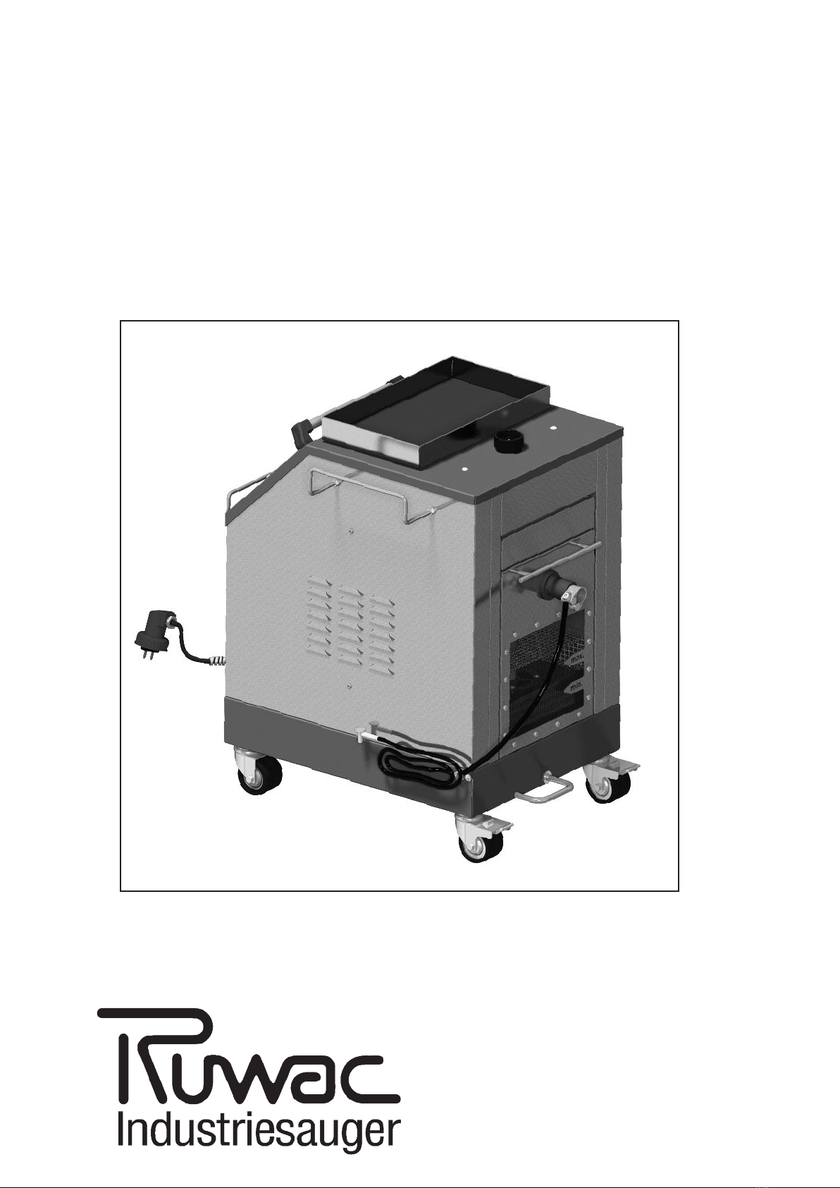
4
3. Health and safety
Read the instruction manual
carefully before installing or
commissioning the wet separa-
tor, paying particular attention to
the safety precautions. Follow all
instructions exactly.
The customer must ensure that
the wet separator is only operat-
ed and maintained by suitably
skilled personnel. Operators
must be instructed and trained
by an authorised person before
using the equipment for the first
time. Staff must be informed dur-
ing this training of all relevant
safety precautions, prohibited
uses and any potential risks
involved.
The wet separator must only be
operated, maintained and
repaired by authorised, skilled
and suitably trained personnel.
All working procedures which
endanger the safety of persons,
the wet separator or the working
environment are strictly forbid-
den.
The operator must immediately
report any safety critical faults
which occur on the equipment to
the person in charge.
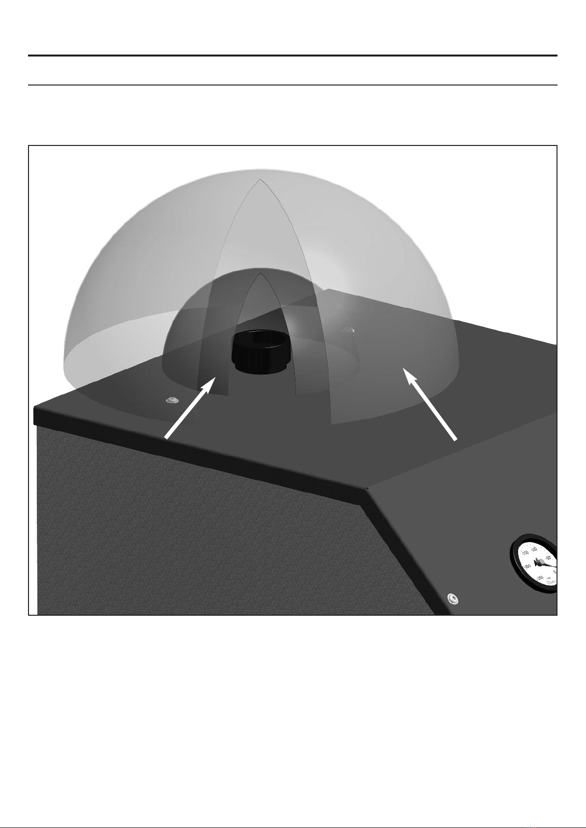
Check the fill level in the wet sep-
arator through the viewing panel
before commissioning and
before each start-up, and at regu-
lar intervals during operation.
The Ruwac wet separator is a state-of-
the-art product and is safe to operate.
However, the safety of this equipment
cannot be guaranteed if it is used by
untrained personnel, operated incor-
rectly or used for purposes other than
those intended
3.1 Information on health
and safety
The equipment must be inspected at
regular intervals in accordance with
German safety regulations BGV A3.
Observe the warning signs on the
equipment.
Do not allow under-age persons to use
the equipment.
Switch off the equipment during breaks
in working.
Ensure that repair work is only carried
out by authorised RUWAC service
technicians.
During maintenance and repair work,
observe the special safety precautions
for working with electrical equipment
and hazardous dust.
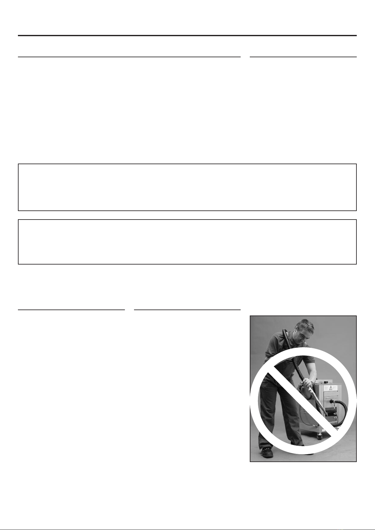
Switch off and unplug the wet separa-
tor before repairing any faults.
Do not modify, bypass or remove safe-
ty devices or guards.
f a fault or hazard occurs, switch off
the wet separator immediately.
Always switch off and unplug the wet
separator before carrying maintenance
and replacing parts.
Check the mains cable at regular inter-
vals for signs of damage.
Do not use the wet separator if the
power supply cable is damaged.
Ensure that the power supply cable
cannot be driven over, crushed,
strained or damaged in any way.