manuals.online logo
Brands
  1. Home
  2. •
  3. Brands
  4. •
  5. RVR Solar
  6. •
  7. Heater
  8. •
  9. RVR Solar Condor 1600 User manual

RVR Solar Condor 1600 User manual

Condor Aluminium Radiator Instructions
Specifications
Material: Die cast aluminium
Connections: 1” nipples
Operating Pressure: 6 bar
pH: 6 to 8.5
Max Temperature: 0°C
Standard Colour: RAL 010 Faral
Guarantee for 10 years once installed in accordance with instructions.
General
The pH values must be between 6.5 and 8.5. Within these values, the aluminium surface will be
sealed and protected from any corrosion. In all cases, it is preferable to use specific corrosion inhibi-
tors, please contact RVR for advice.
The presence of corrosive waters in the system will make the warranty null and void.
The heating circuit must be supplied with a suitable earth connection, in compliance with Standards.
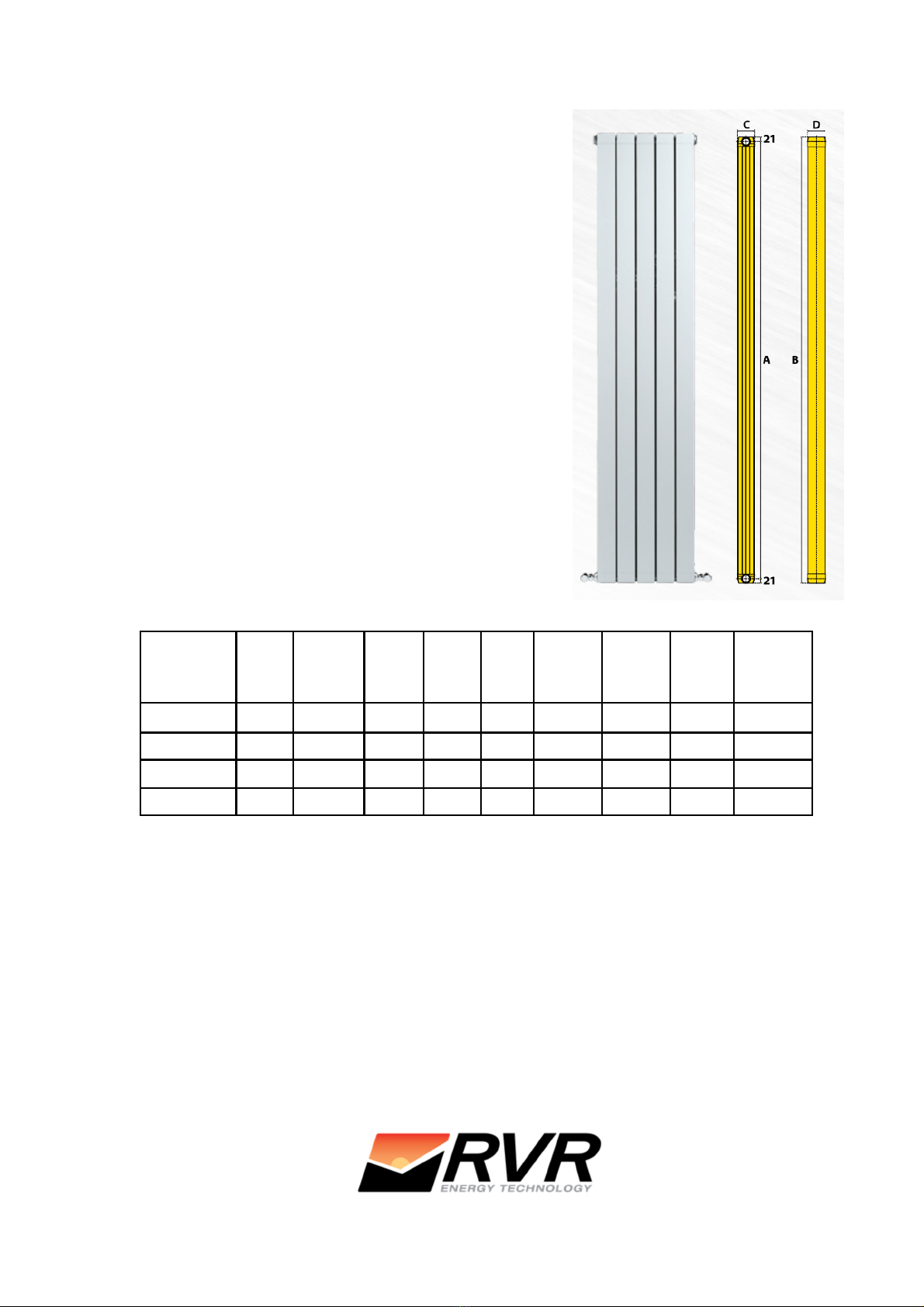
For wall positioning or under windows the following DISTANCES are recommended:
From the floor: 120 mm
From the wall: 30 mm
From the shelf/window sill: 120 mm.
Every set of radiators installed must be equipped with an automatic or manual air vent valve.
The radiators are die-cast aluminium, therefore they must be HANDLED WITH CARE during as-
sembly.
Care & Maintenance
The radiators are protected and finished on the surface with a double coat of paint, one integral with
anaphoresis application methods, and one in epoxy polyester powder with electrostatic deposit.
Therefore they cannot be readjusted or other paints applied.
To clean the surface USE NEUTRAL NON-ABRASIVE PRODUCTS. It is also recommended NOT
TO COVER THE RADIATOR with damp cloths, wet clothing or porous objects.
ATT: If the radiator must be bled very often, contact your technician or our technical dept. directly.
The radiators produced by INDUSTRIE PASOTTI S.p.A. are guaranteed if used in compliance with
the relevant standards and if installed by qualified staff with respect to the code of practice. The war-
ranty covers the radiator from any manufacturing faults. The warranty comes into force on the date of
the purchase document. Working pressure is certified according to the EN 442/1/2 Standard.
Step by Step Guide to Joining Radiators
Radiator must be laid on a flat surface before commenc-
ing joining. (See figure 1)
The joining surface must be clean. The surface can be
painted or unpainted from the factory. If it’s painted make
sure that the paint is not chipped.
If chipped paint is present, surface must be sanded to
ensure a clean surface.
If the surface is painted clean with no chips, that is satis-
factory.
Figure 1—Top of radiator
The radiators must be joined using 1 o– ring for
each nipple, which is to be fitted dry. The nipple is
to be turned clockwise on the right hand side and
to be turned anti-clockwise on the left hand side.
Figure 2—Joining Nipples
Position radiators together with nipple threads just
located together and not turned in.
Pull the two radiators together.
Pull radiators together. Mark
the depth of the radiator on the
joining key.
Figure 4 —Joining key
Clockwise (RHS) Anticlockwise (LHS)
Figure 3—nipples and o—rings in place
Joining Nipples
Tighten top and bottom of radiator evenly by turning nip-
ples a small bit at a time alternating between top and bot-
tom to ensure that they are joined evenly.
Uneven tightening can result in damaged
mating surfaces, resulting in leaks see figure
6.
Take care to tighten the nipples on top and
bottom evenly.
Figure 5 —Tighten radiators
Mounting Radiators
Wall brackets are used to mount the radiator to the wall. Four brack-
ets are required per radiator. SRP 15, universal fitting pack plus
SRP 17 is required for each radiator.
They must be positioned between the radiator sections, i.e. 81mm from edge of radiator.
To work out the vertical position of the brackets, first calculate the distance between the floor and the
centre of the lower pipe, feeding into the lower header of the radiator.
The drilling distance is 15mm down from the pipe centre, as shown in figures 7 and 8 below.
The centre of the top bracket is either 1600 or 2000 mm up from the lower bracket, depending on
which size radiator is being installed.
When fitting the reducer to the radiator, ensure that the left hand thread goes on the left of the radia-
tor and the right thread goes on the right side. The rubber rings on the reducer must be replaced
(figure 7) with the O-rings from RVR (figure 8).
Figure —Wall brackets
(SRP 17), including rawl plug
Figure 10 —Top of radiator
Figure 7—Remove rubber
ring on reducer
Figure 8—Replace with O-
ring from packet
Figure 11 —Bottom of radiator
Figure 6 —Uneven tightening
Radiator Specifications
CE 442-1 Radiators and Convectors
A—Distance between Centres
B—Height
C—Depth
D—Width
Terms & Conditions
All products must be inspected once removed from the packaging and RVR notified within 28 days of
delivery of any scratches, blemishes or other damage. RVR will then replace the radiator.
Imperfect radiators should therefore not be fitted and RVR will not accept responsibility for replace-
ment of scratched or damaged radiators once they have been fitted. This includes any consequential
loss or cost of fitting.
If RVR are not notified within 28 days of the date on the signed delivery note then it will be deemed
that RVR have fully complied with its obligations and claims will not be considered.
Failure to comply with any of the above may invalidate any claims.
We recommend that after you check the product on delivery and that it is stored in its packaging to
prevent damage prior to installation. RVR cannot accept responsibility for items damaged after deliv-
ery.
Model No of
Sec-
tions
Height
(mm)
Width
(mm)
Depth
(mm)
Output@
Δ T 50 o
C (W)
Output@
Δ T 30 o
C (W)
Water
Content
(l)
Max
Operating
Pressure
(bar)
Condor 1600 31642 240 80 744 372 1.86 6
Condor 1600 51642 400 80 1240 620 3.1 6
Condor 2000 32042 240 80 87 408 2.25 6
Condor 2000 52042 400 80 1465 735 3.75 6
Distance
between
centres
(mm)
1600
1600
2000
2000
ATTENTI N: the installer is requested to leave a copy of this document with the customer.
Kenmare, Co. Kerry, V93 F386, Ireland
+353 64 6641344
in o@rvr.ie
www.rvr.ie

This manual suits for next models

1

Popular Heater manuals by other brands

Outsunny SUNDEAR GS 1500 Assembly & operation instructions

Outsunny

Outsunny SUNDEAR GS 1500 Assembly & operation instructions

Electric House 69531 instruction manual

Electric House

Electric House 69531 instruction manual

Pakole GTV-E-20A user manual

Pakole

Pakole GTV-E-20A user manual

Zibro SRE 229 E operating manual

Zibro

Zibro SRE 229 E operating manual

MCS Master B 2 PTC User and Maintenance Book

MCS Master

MCS Master B 2 PTC User and Maintenance Book

Valley Comfort Systems VC95C Installation and operation manual

Valley Comfort Systems

Valley Comfort Systems VC95C Installation and operation manual

Klarstein WONDERWALL SMART 960 manual

Klarstein

Klarstein WONDERWALL SMART 960 manual

Rowenta SO9010 manual

Rowenta

Rowenta SO9010 manual

Desa Master WA 33 B user manual

Desa

Desa Master WA 33 B user manual

ARDES AR4F02 Instructions for use

ARDES

ARDES AR4F02 Instructions for use

Remington REM-60VBOA-GFA-B User's manual & operating instructions

Remington

Remington REM-60VBOA-GFA-B User's manual & operating instructions

Alesco ACE12 manual

Alesco

Alesco ACE12 manual

Prem-I-Air Elite EH1264 quick start guide

Prem-I-Air Elite

Prem-I-Air Elite EH1264 quick start guide

Kaisai GOLD AU-100H6 installation manual

Kaisai

Kaisai GOLD AU-100H6 installation manual

Roberts Gorden Combat UHA[X][S] 100 Installation & operation

Roberts Gorden

Roberts Gorden Combat UHA[X][S] 100 Installation & operation

Dimplex QXD1500ND Installation and operating insctructions

Dimplex

Dimplex QXD1500ND Installation and operating insctructions

Winterwarm XR+ Series installation manual

Winterwarm

Winterwarm XR+ Series installation manual

Whirlpool HT220 user manual

Whirlpool

Whirlpool HT220 user manual

manuals.online logo
manuals.online logoBrands
  • About & Mission
  • Contact us
  • Privacy Policy
  • Terms and Conditions

Copyright 2025 Manuals.Online. All Rights Reserved.