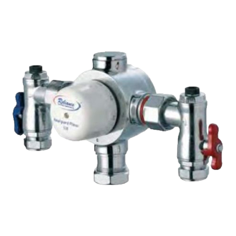
RWC Heatguard Planar 230 User manual

Thermostatic mixing valve for use in group mixing applications.
Installation and Maintenance Instructions
Heatguard®Planar
Thermostatic Mixing Valves
Reliance Worldwide Corporation (UK) Ltd
Worcester Road,
Evesham,
Worcester,
WR11 4RA,
UK
Tel: +44 (0)1386 712 400
Fax: +44 (0)1895 712 401
www.rwc.co.uk
Reliance Worldwide Corporation (UK) Ltd reserves the right to make changes to the
product which may affect the accuracy of information contained in this leaflet.
ZINS530002_004_11-15

14
Contents
Reliance Worldwide Corportation (UK) Ltd....... 2
General Information...........................................3
Specification...................................................... 3
Flow rates..........................................................4
Installation......................................................... 4
Commissioning.................................................. 5
Dimensions........................................................7
Maintenance...................................................... 8
Spares & Care Instructions............................... 11
Troubleshooting................................................. 12
1
Notes

213
Notes
Reliance Worldwide Corporation (UK) Ltd
Reliance Worldwide Corporation (UK) Ltd are part of the Australian
based group of companies collectively known as Reliance Worldwide
Corporation, with the UK brand known as Reliance Water Controls.
Reliance Worldwide Corporation (UK) Ltd is a specialist in the design,
distribution and technical support for temperature and flow controls.
With group offices and manufacturing plants throughout the world
RWC offers a wealth of knowledge and expertise which is reflected
throughout our products. Being part of many specialised trade
associations and having our own UKAS accredited laboratory, makes
us at the forefront of any new regulations or changes which impact
the industry, and allows for continous product development and
innovation, within our specialised product area.
Our core product range is related to thermostatic control, with the
manufacturing undertaken at our head office in Brisbane Australia,
we have an extensive range of thermostatic mixing valves, shower
control valves, and taps all which use the same high quality
technology to control the temperature of water, within this range
we have different valves to suit various applications and working
parameters, including both TMV2 and TMV3 approved controls.
RWC, are market leaders of OEM controls with a complete range
of safety valves for use in G3 unvented systems and a wide range
of Underfloor heating controls (UFH) to allow for safe distribution of
hot water, throughout a property. This range includes; thermostatic
control valves for safe hot water temperatures, manifolds to enable
even distribution, complete UFH kits to allow ease of installation &
commisioning, and a range of modern and stylish programmers to
complement these controls.

General Information
Please read these instructions carefully and ensure that the mixing valve is
installed to Local Authority Regulations.The Heatguard®Planar thermostatic
mixing valves are suitable for use on low pressure hot and cold water
supplies down to a minimum of 0.2 Bar dynamic pressure (2 metre head)
when used with the appropriate low pressure shower heads. For best
performance the recommended dynamic pressure range is 0.5 - 2.0 Bar
(5 - 20 metres head) with a pressure loss ratio of no more than 2:1. The
thermostatic shower is factory preset to 41°C ± 3°C with a balanced flow
pressure of 2 bar. If the maximum temperature setting is affected due to
special installation conditions, the thermostat can be adjusted on site to
compensate.
Specification
Planar 230 Planar 330 Planar 430 Planar 530
Minimum flow
pressure: 0.2 Bar 0.2 Bar 0.2 Bar 0.2 Bar
Test pressure static: 16 Bar 16 Bar 16 Bar 16 Bar
Working pressure: 3.5 Bar 3.5 Bar 6 Bar 6 Bar
Maximum pressure
loss ratio: 2:1 2:1 2:1 2:1
Maximum hot water
temperature at the
inlet:
85°C 85°C 85°C 85°C
Recommended stored
temperature: 60°C 60°C 60°C 60°C
Minimum hot/blend
temperature difference
to ensure shut-off on
cold supply failure:
15°C 15°C 15°C 15°C
Factory setting at 2
bar equal pressures: 41°C ± 3°C 41°C ± 3°C 41°C ± 3°C 41°C ± 3°C
Minimum flow rate: 5 LPM 6 LPM 8 LPM 8 LPM
Flow rate at 2.5
Bar: 50 LPM 79 LPM 120 LPM 170 LPM
At flow pressures of over 3.5 Bar, or when the differential is >2:1, it is
recommended that a Reliance pressure reducing valve be fitted in the supply line(s).
Troubleshooting
I can only get hot or cold water from the outlet
Check that the valve is connected up correctly, with the hot and cold
supplies connected the corresponding fittings on the valve.
Check that the supplies are both working correctly.
Check non-return valves and strainers in inlet fittings for blockages and
clean if necessary.
Check that supply conditions are within those stated in the working
parameters at the beginning of this booklet.
I am getting fluctuating mixed outlet temperature
Debris is fouling the valve causing it to become sluggish. Service valve as
per maintenance instructions.
Check non-return valves and strainers in inlet fittings for blockages and
clean if necessary.
I am getting fluctuating and/or poor flow rates
Check non-return valves and strainers in inlet fittings for blockages and
clean if necessary.
Check isolation valves are fully open.
Check that supply conditions are within those stated in the working
parameters at the beginning of this booklet.
I am getting cross flow of hot water into the cold water supply or vice
versa
Check non-return valves and strainers in inlet fittings for blockages and
clean if necessary.
Check that supply conditions are within those stated in the working
parameters at the beginning of this booklet.
The valve will not shut down
Check that the hot supply to mix temperature differential is a
minimum of that stated in the working parameters.
Debris is fouling the valve causing it to stick. Service valve as per
maintenance instructions.
3 12

Flow Rates
Installation
Offer up the valve to the system and mark out where it is to be fitted. With
the smaller of the provided allen keys loosen the grub screws securing the
fixing ring to the back of the valve and remove it.
Mark out, drill, rawl plug the fixing
holes and secure the fixing ring to the
wall (the mounting surface must be
strong enough to take the weight of
the valve).
Fit the valve to the fixing ring and
tighten the grub screws evenly.
4
11
020 40 60 80 100 120 140 160 180 200
0.00
0.50
1.00
1.50
2.00
2.50
3.00
3.50
4.00
Flow Rate (litres/min)
530
430
Pressure Loss (Bar)
230 330
Spares
Description Product Code
Full internal service kit for Planar 230: SKIT230100
Full internal service kit for Planar 330: SKIT330100
Full internal service kit for Planar 430/530: SKIT430001
Planar 230/330 4 in 1 adaptor service kit: SKIT300020
Planar 430/530 4 in 1 adaptor service kit: SKIT300016
Hot 4 in 1 service fitting for Planar 230: ZSER271007
Cold 4 in 1 service fitting for Planar 230: ZSER271008
Hot 4 in 1 service fitting for Planar 330: ZSER271003
Cold 4 in 1 service fitting for Planar 330: ZSER271004
Care Instructions
Care must be taken when cleaning the valve. Do not use any cleaning
products on the mixing valve as over time this will have an adverse effect
on the finish. Instead, wipe clean regularly with a soft cloth to prevent lime
scale build up and to remove dirt and dust.

Flush out pipes - It is important that both supply pipes are flushed
thoroughly before connecting the thermostatic valve to ensure that no pipe
work or plumbing debris enters the valve. It is possible to use the ¼” BSP
fitting on the inlet connections with an appropriate pipe to do this. Under no
circumstances should the system be flushed through the valve.
The main valve connections
are colour coded as well as
the 4 in 1 connections. The
outlet connection can be
altered to change the
configuration of the valve.
This must be done with care
using tools of the correct size
to avoid damage to the
surface finish of the valve.
Commissioning
The Heatguard®Planar thermostatic mixing valves are supplied factory set
at 41°C with 2 Bar equal pressures in a non adjustable form. There are
three forms in which these valves can be commissioned:
1 They can be commissioned at any fixed non-adjustable temperature
between 35°C and 50°C.
2 They can be commissioned in an adjustable form with a set maximum
temperature.
3 They can be commissioned in an adjustable form with no preset
maximum temperature.
General
Ensure that both water supplies are turned on and that the hot water
temperature is 60°C minimum. Check that the dynamic water pressure on
both hot and cold supplies is within the working parameters of the valve at
the installations maximum and minimum flow rates. If the hot and cold water
pressure differential is greater than 2 : 1 then pressure reducing valves may
be required.
510
6. With the spring removed the main o-ring seal can be seen. This should
be inspected, cleaned and re-greased. If the o-ring is damaged it must
be replaced.
7. The piston assembly should be inspected paying particular attention
to the area which the main o-ring seals and the top and bottom edges
of the piston. If there is any damage the damaged component must be
replaced.
8. The 4 in 1 fitting can be stripped down with the exception of the check
valve cartridge which, if removed, has to be replaced with a new
cartridge.

Setting the pre-set temperature in the non-adjustable form.
Remove the cap and the cam. Refit the cap
and, at approx. 50% flow rate, adjust the
temperature to the required preset
temperature. Remove the cap and refit the cam
so that the index mark on the body is between
the two lugs on the cam. Refit the cap with the
index mark on the body between the Max and
Min markings on the cap and check the
temperature at the maximum and minimum
flow rates. There should be no more than a
3°C difference from the nominal temperature
setting and the cap should be locked in position.
Setting the maximum temperature in the adjustable form with a
maximum pre-set temperature.
Remove the cap and the cam. Refit the cap and, at approx. 50% flow rate,
adjust the temperature to the required maximum temperature. Remove the
cap and refit the cam with the figures indicating the preset temperature lined
up with the index mark on the body. Refit the cap with the maximum
temperature figure aligned with the index mark. The cap should not be able
to rotate anti-clockwise. Check the maximum temperature is correct.
Commissioning in an adjustable form with no pre-set maximum
temperature.
Remove the cap and the cam. Refit the cap and, at approx. 50% flow rate,
adjust the temperature to 52°C. Remove the cap and refit the cam so that
the index mark on the body is between the two lugs on the cam. Refit the
cap with the MAX marking lining up with the index mark on the body. Check
that the cap does not move anti-clockwise but does move clockwise.
Record the system conditions and
valve settings so that they can be
used during valve maintenance.
6
9
Once the valve is accessible for servicing, proceed as follows:
1. Access has to be gained to the thermostatic mechanism. To do this
remove the control knob and temperature cam.
2. Remove the head work using a spanner. If an adjustable spanner is
used make sure it is correctly adjusted to avoid damage to the head.
3. The first thermostatic element can now be removed.
4. Followed by the piston which can be lifted out. This will reveal the return
spring which can also be removed.

Dimensions
A B C D E F G H
HEAT230100 100 85 185 250 25 70 125 3/4" BSP
HEAT330100 135 105 245 320 30 95 127 1" BSP
HEAT430100 170 125 275 355 40 105 127 1.1/4" BSP
HEAT530100 180 125 275 355 40 105 127 1.1/4" BSP
All dimensions in mm unless otherwise stated
A
B
C
D
H
E
F
G
AED
C
BG
FH
180
All dimensions in mm
unless stated
125 275 355 40 105 127 1.1/4" BSP
HEAT 530 100
HEAT 530 200 105 127 1.1/4" BSP
180 110 285 385 40
170 125 275 355 40 105 127 1.1/4" BSP
HEAT 430 100
(Illustrated)
78
Maintenance
If the performance of the thermostatic valve has deteriorated over time, the
valve will require maintenance.
1. First isolate the hot and cold supplies via the service valves and
thoroughly flush the line strainers in the 4 in 1 fittings. The system
should be checked and any additional strainers in the supply should
also be flushed.
2. Ensure that the shower heads / outlets are clean and free from
limescale.
3. Turn the hot and cold supplies back on and then carry out the following
checks:
3.1. Check if the flow performance has returned to normal.
3.2. Check that the temperature setting (pre-set, pre-set maximum or
maximum temperature) has been retained at maximum and minimum
flow rates.
3.3. Check that the thermostatic valve fails safe when the cold water
fails (N.B. before carrying out this test ensure the valve mechanism is
exercised by turning off and on the hot and cold supplies alternately a
minimum of 3 times). Turn off the cold water supply - the water flow from
the shower should reduce to a residual flow within 3-4 seconds.
If any of the above are not as specified, check that supply conditions have
not changed. If system conditions (pressure, temperature, etc.) have altered
since the valve was commissioned a check should be made to verify that
they are still within the valves working parameters.
Temperature - Slower shut-off times may indicate that the hot water is not
15°C hotter than the blended water.
Pressure - Lower flow rates may indicate reduced supply pressure, blocked
strainers or lime scale build up.
The Heatguard®Planar 430 and 530 thermostatic mixing valves are
constructed from high quality materials and the shuttle is resistant to lime
scale build up; however, if the supply conditions are as specified and the
valve is sluggish in operation the unit can be serviced.
Remove the valve from the installed position by first turning off the service
valves and then disconnecting at the 4 in 1 union connections.
This manual suits for next models
3
Table of contents
Other RWC Control Unit manuals