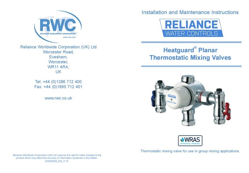
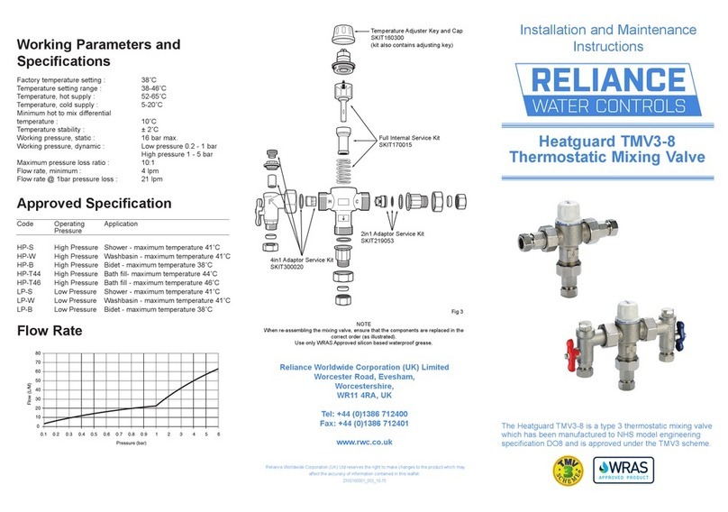
RWC PLANAR 230 User manual

Reliance Water Controls
Worcester Road
Evesham
Worcestershire
WR11 4RA
Tel: 01386 47148
Fax: 01386 47028
www.rwc.co.uk
ZINS230100-001-03/07
Installation and Maintenance Guide
PLANAR 230 & 330
THERMOSTATIC
MIXING VALVES

GENERAL FUNCTION
Please read these instructions carefully and ensure that the mixing valve is
installed to Local Authority Regulations.
The Planar™ 230 and 330 thermostatic mixing valves are suitable for use
on low pressure hot and cold water supplies down to a minimum of 0.2
bar dynamic pressure (2 metre head) when used with the appropriate low
pressure shower heads. For best performance the recommended dynamic
pressure range is 0.5 - 2.0 bar (5 metre- 20 metre head) with a pressure
loss ratio of no more than 2:1.The thermostatic shower is factory preset
to 41°C ± 3°C with a balanced flow pressure of 2 bar. If the maximum tem-
perature setting is affected due to special installation conditions, the ther-
mostat can be adjusted on site to compensate.
WORKING PARAMETERS AND SPECIFICATIONS
Planar™230 Planar™330
Minimum flow pressure: 0.2 bar 0.2 bar
Test pressure static: 16.0 bar 16.0 bar
Working pressure dynamic: 3.5 bar max. 3.5 bar max.
Maximum pressure loss ratio: 2:1 2:1
Maximum hot water
temperature at the inlet: 85°C 85°C
Recommended stored
temperature: 60°C 60°C
Minimum hot/blend
temperature difference to
ensure shut-off on cold
supply failure: 15°C 15°C
Factory setting at 2 bar
equal pressures: 41°C ± 3°C 41°C ± 3°C
Minimum flow rate 8 LPM 10 LPM
Flow delivery at 40°C mixed
water temperature at 1
bar pressure loss: 75 LPM 110 LPM
At flow pressures of over 3.5 bar, or when the differential is >2:1, it is
recommended that a Syr pressure reducing valve be fitted in the supply
line(s).
low rate
NOTES
Flow rate

DIMENSIONS
rate
A
B
C
D
H
E
F
G
AED
C
BG
FH
All dimensions in mm unless stated
HEAT 230 100
135 105 245 320 30 95 127 1" BSP
HEAT 330 100
100 85 185 250 25 70 125 3/4" BSP
NOTES
Flow rate

INSTALLATION
Thermostatic mixing valves are temperature sensitive appliances so must not
be subjected to extreme temperatures (either hot or cold) in use or
installation.
BRAZING OR SOLDERING ON OR NEAR THE MAIN VALVE BODY MUST BE
AVOIDED.
The valves should be fitted where they can be easily accessed for
commissioning and maintenance.
Offer up the valve to the system and mark out where the valve is to be fitted.
With the smaller of the provided Allen keys loosen the grub screws securing
the fixing ring to the back of the valve and remove it.
Mark out, drill and rawplug the fixing holes and secure the fixing ring to the
wall (the mounting surface must be strong enough to take the weight of the
valve).
Fit the valve to the fixing ring and tighten the grub screws evenly.
COMMISSIONING
The Euromixer thermostatic mixing valve is supplied factory set at 41°C with
2 bar equal pressures in a non adjustable form. There are three forms in which
this valve can be commissioned:
1. It can be commissioned at any fixed non-adjustable temperature
between 35°C and 50°C.
2. It can be commissioned in an adjustable form with a set maximum
temperature.
3. It can be commissioned in an adjustable form with no preset
maximum temperature.
General
Ensure that both water supplies are turned on and that the hot water
temperature is 55-60°C minimum. Check that the dynamic water pressure on
both hot and cold supplies is within the working parameters of the valve at
the installations maximum and minimum flow rates. If the hot cold and cold
water pressure differential is greater than 2 : 1 then pressure reducing valves
may be required.
w rate
TROUBLE SHOOTING
I CAN ONLY GET HOT OR COLD WATER FROM THE OUTLET?
• Checkthatthevalveisconnectedupcorrectly,withthehot
and cold supplies connected the corresponding fittings on
the valve.
• Checkthatthesuppliesarebothworkingcorrectly.
• Checknon-returnvalvesandstrainersininletfittingsfor
blockages and clean if necessary.
• Checkthatsupplyconditionsarewithinthosestatedinthe
working parameters at the beginning of this booklet.
I AM GETTING FLUCTUATING MIXED OUTLET TEMPERATURE?
• Debrisisfoulingthevalvecausingittobecomesluggish.
Service valve as per maintenance instructions.
• Checknon-returnvalvesandstrainersininletfittingsfor
blockages and clean if necessary.
I AM GETTING FLUCTUATING AND/OR POOR FLOW RATES?
• Checknon-returnvalvesandstrainersininletfittingsfor
blockages and clean if necessary.
• Checkisolationvalvesarefullyopen.
• Checkthatsupplyconditionsarewithinthosestatedinthe
working parameters at the beginning of this booklet.
I AM GETTING CROSS FLOW OF HOT WATER INTO THE COLD WATER
SUPPLY OR VICE VERSA?
• Checknon-returnvalvesandstrainersininletfittingsfor
blockages and clean if necessary.
• Checkthatsupplyconditionsarewithinthosestatedinthe
working parameters at the beginning of this booklet.
THE VALVE WILL NOT SHUT DOWN?
• Checkthatthehotsupplytomixtemperaturedifferential
is a minimum of that stated in the working parameters.
• Debrisisfoulingthevalvecausingittostick.Servicevalve
as per maintenance instructions.

1. Setting the preset temperature in the non-adjustable form.
• Removethecapandthecam.
• Refitthecapand,atapprox.50%flowrate,adjustthe
temperature to 40°C.
• Removethecapandrefitthecamsothattheindexmarkonthe
body is between the two lugs on the cam.
• RefitthecapwiththeindexmarkonthebodybetweentheMax
and Min markings on the cap and check the temperature at the
maximum and minimum flow rates. There should be no more
than a 3°C difference from the nominal temperature setting.
• Thecapshouldbelockedinposition.
2. Setting the maximum temperature in the adjustable form with
a maximum preset temperature.
• Removethecapandthecam.
• Refitthecapand,atapprox.50%flowrate,adjustthe
temperature to the required maximum temperature.
• Refitthecapwiththefiguresonthecapindicatingthemaximum
temperature aligned with the index mark on the body.
• Markonthebodyofthevalve(useafelttiporsimilartemporary
marker) the point between the Max and Min marks.
• Removethecapandfitthecamsothattheouteredgeofthe
clockwise lug line up with the temporary mark.
• Refitthecapwiththemaximumtemperaturefigurealignedwith
the index mark. The cap should not be able to rotate
anti-clockwise.
• Checkthemaximumtemperatureiscorrect.
3. Commissioning in an adjustable form with no preset maximum
temperature.
• Removethecapandthecam.
• Refitthecapand,atapprox..50%flowrate,adjustthe
temperature to 40°C.
• Removethecapandrefitthecamsothattheindexmarkonthe
body is between the two lugs on the cam.
• Refitthecapwiththe40°Cmarkingliningupwiththeindex
The inlet fittings can be stripped down
and cleaned except for the non-return
valve that, if removed, needs to be
replaced by a new cartridge.
In-service tests and any necessary maintenance should be carried out
on a regular basis, at least once a year. A record of the results should be
retained for future checks.
Flow rate
INLET
STRAINER
NON-RETURN
VALVE
1/4" TEST
PLUG

mark on the body is between the two lugs on the cam.
• Refitthecapwiththe40°Cmarkingliningupwiththeindexmark
on the body.
• Checkthatthecapmovesbetweenthemaximumandminimum
marking.
Record the system conditions and valve settings so that they can be used
for valve maintenance.
MAINTENANCE
If water conditions or installation conditions are severe, and the valve is slug-
gish in operation, it is possible that there is a build up of scale within the
valve. the valve can then be stripped down and cleaned very easily.
1. Isolate the hot and cold supplies and remove the main body of the
valve from the installation.
2. Remove the control knob and cam.
3. Remove the headwork using a spanner. If using an adjustable
spanner ensure it is correctly adjusted to avoid damage to the head
work.The headwork can now be removed. (Fig 5)
4. The thermostatic element and piston can be lifted out.This leaves
the return spring, which can then also be lifted out. Ensure you note
the orientation of all the components so that they can be
re-assembled in the correct order.
5. With the spring removed the ‘O’ ring seal can be inspected,
cleaned and re-greased. If the ‘O’ ring is damaged it must be
replaced.
6. The components removed should be inspected and if any are
damaged they must be replaced.
7. Line strainers should be removed from the inlet fittings and rinsed
in clean water. The pipework should then be flushed to remove any
contamination that has fallen back down into the pipe.
8. If it is thought that cross flow is taking place, the check valves
should be removed from the inlet fittings, rinsed in clean water and
then replaced. The check valves can be removed by using a pair of
long nosed pliers, pulling them evenly on one of the fins. Do not
attempt to lever the check valves out, as this will damage them.
After cleaning and re-assembly, the valve should be reset and tested.
This manual suits for next models
1
Table of contents
Other RWC Control Unit manuals
Popular Control Unit manuals by other brands

Technica Engineering
Technica Engineering TE-1437 user manual

Alfalaval
Alfalaval Unique 7000 Series instruction manual

Ublox
Ublox SARA-N210 System integration manual

Ublox
Ublox NINA-B31 Series Getting started

Delta
Delta ASRTU-EC16AP Operation manual

Alfalaval
Alfalaval Unique Mixproof Horizontal Tank instruction manual