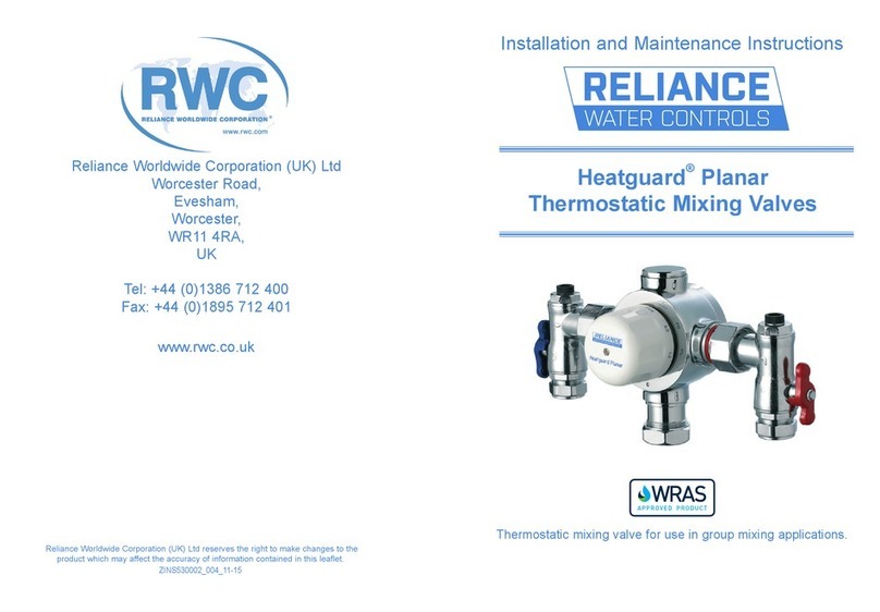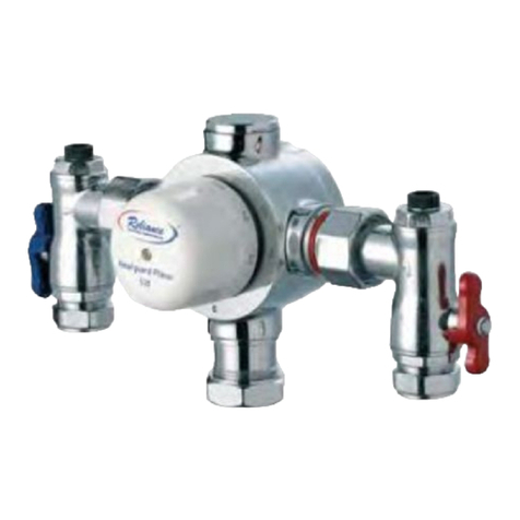
1. Remove the screw which secures
the cap by using the allen key
provided then lift the cap off.
2.With both the hot and cold supplies
turned fully on and a terminal fitting
open, adjust the temperature to the
required setting, by using the cap to turn the adjustment
spindle.
3.Turn the cap clockwise to decrease or
anti-clockwise to increase the temperature.
4. A digital hand-held thermometer should
be used to measure the outlet temperature
correctly.
5. Once the correct temperature has
been set re-fit the cap, ensuring it is
secured through the slots on the locking
ring so that the valve cannot be adjusted
by the end user.
6. Once the correct outlet temperature
has been achieved the valve’s internal
mechanism should be exercised at least
3 times by alternately isolating the hot
and cold supplies. This will cause the piston to travel its full
stroke and will ensure that the valve is operating correctly. If
the set temperature has drifted after this operation then the
commissioning process should be repeated.
7. Once the valve has been commissioned a cold water
supply shut off test should be performed.
a. Isolate the cold supply, the flow should reduce to a trickle
within a second or two depending on site conditions.
b. Restore the cold supply and check that the set
temperature has not altered.
c. Repeat the test for the hot supply.
8. If either test does not show correct performance, ensure
that supply pressures and temperatures are within the
valve’s normal operating parameters. In addition, check
thatthehotsupplytemperatureisatleast10˚Cabove
the valve’s set mixed outlet temperature i.e. hot to mix
differential temperature.
If this is not the case then the valve will be slow to shut
down on cold water failure.
9. For optimum performance it is recommended that the
dynamic pressures be as close to equal as possible. If the
dynamic pressures are outside a 10:1 ratio then a pressure
reducing valve should be fitted to the higher supply pressure
or if preferred, the lower supply pressure boosted.
Reliance Worldwide Corporation (UK) Ltd
Reliance Worldwide Corporation (UK) Ltd are part of the
Australian based group of companies collectively known as
Reliance Worldwide Corporation, with the UK brand known
as Reliance Water Controls.
Reliance Worldwide Corporation (UK) Ltd is a specialist
in the design, distribution and technical support for
temperature and flow controls.
With group offices and manufacturing plants throughout
the world RWC offers a wealth of knowledge and expertise
which is reflected throughout our products. Being part of
many specialised trade associations and having our own
UKAS accredited laboratory, makes us at the forefront of
any new regulations or changes which impact the industry,
and allows for continuous product development and
innovation, within our specialised product area.
Installation
Before installing the Heatguard Base valve ensure that
the designation of the valve matches the application.
Flow rates, dynamic pressures, and temperatures must
be within the limits stated, as valves operating outside of
these conditions of use, cannot be guaranteed to operate
correctly, as either a type 2 or 3 valve. The valve must
be installed in accordance with the Water Supply (Water
fittings) Regulations 1999 and any relevant building
regulations, specific to the application. Isolation valves must
be fitted adjacent to the hot & cold water inlet supplies to
the Heatguard Base valve. The Heatguard Base valve can
be installed in any orientation provided that the hot and
cold supplies are connected to the appropriate indicated
inlets.The valve should not be installed until the system
has been flushed free of all debris, and in a position in
which maintenance and commisioning of the valve can be
undertaken.
The Heatguard thermostatic mixing valve contains
temmperature sensitive components. Soldering near the
valve body must be avoided.
Commissioning
Please ensure that the commissioning of the valve is
done under normal operating conditions. The Heatguard
thermostaticmixingvalveissuppliedfactorysetat43˚C.To
alter this setting proceed as follows:
10. A record of the commissioning settings should be made
for comparison with future performance checks.
Please note: If there is a residual flow, then this is
acceptable providing the temperature of the seeping water
isnomorethan2˚Cabovethedesignatedmaximumwater
outlet temperature setting of the valve.
Maintenance
The perfomance of the Heatguard Base Valve should be
checked on an annually basis and verified against the
original installation performance. If the water or installation
conditions are more severe this check should be carried out
more frequently.
Performance check
Performance checks that should be carried out at routine
maintenance times are:
1. Check the set temperature using a hand-held digital
thermometer.
2. Carry out the cold and hot water supply isolation tests.
3. If there is no significant change to the set outlet
temperature(2˚Corlesschangefromtheoriginalsettings)
and the fail-safe shut off is functioning, then the valve is
working correctly and no further service work is required.
Cleaning the valve
1. Isolate the hot and cold supplies and remove the valve
from the installation. Make note of the orientation of the
parts as they are removed so that they can be reassembled
in the correct manner.
2. To clean the internals of the main valve body, first remove
the cap using an allen key remove the plastic locking
ring, then finally carefully remove the valve headwork by
unscrewing the large hex nut.
3. Slide the piston and thermostat assembly out of the valve
body and clean all internal surfaces and o-rings with a weak
solution of scale remover approved for use with potable
water.
4. Using a WRAS approved silicone based waterproof
grease, lightly lubricate the o-ring in the body and the
external surface of the piston.
5. After cleaning, re-assemble the Heatguard Base valve.
Exercise, re-set and test the valve as laid out in the
commissioning section.


