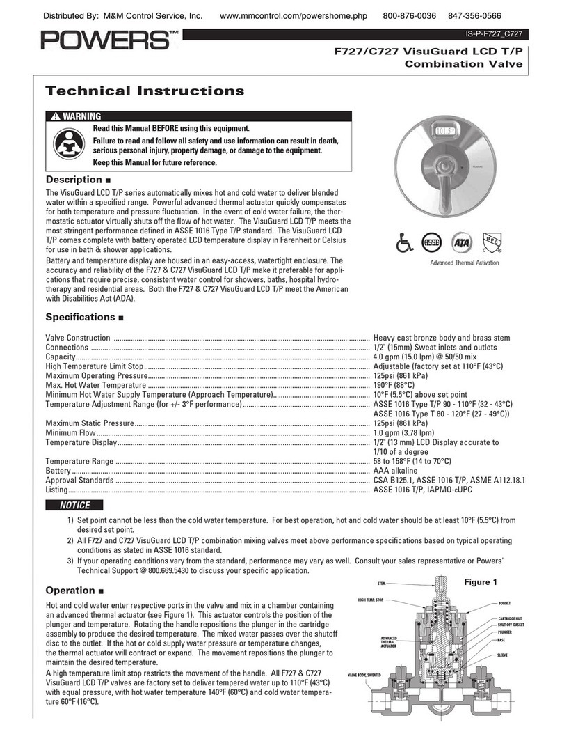
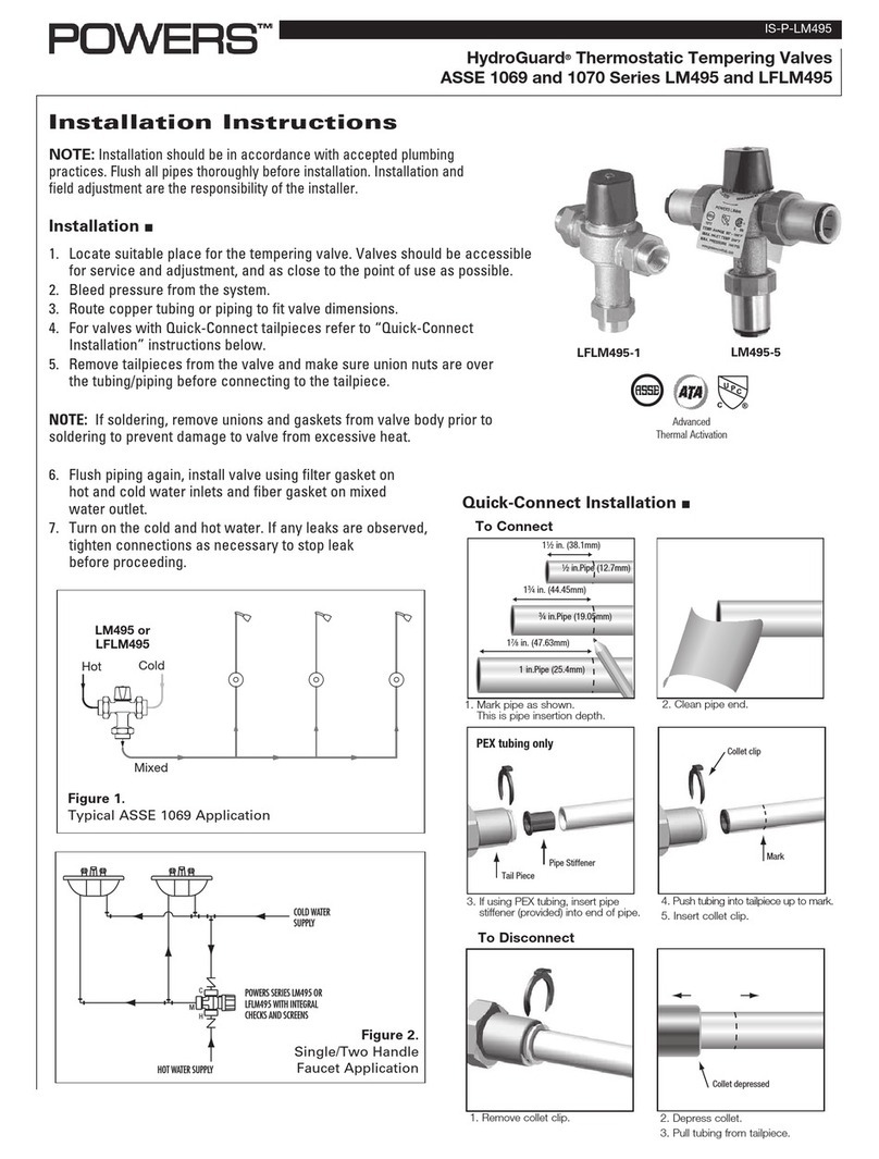
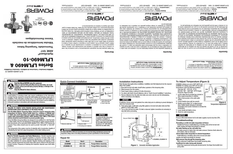
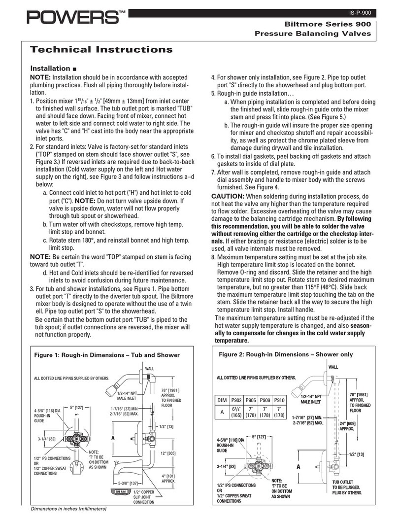
Powers IntelliStation Jr User manual

User Guide & Instruction Manual
IntelliStation
®
Jr.
Digital Water Mixing Valve
Read this Manual BEFORE using this equipment.
Failure to read and follow all safety and use information can result
in death, serious personal injury, property damage, or damage to the
equipment. Visit PowersControls.com with any questions.
Keep this Manual for future reference.
WARNING
!


LIMITED WARRANTY / LIMITATION OF REMEDY:
What is covered? Powers warrants to the original purchaser only, that the product it
manufactured when used as intended and instructed, is free from defects in materials or
workmanship for five year warranty from date of shipment to the original purchaser.
What is not covered? This Limited Warranty does not cover or is voided by (a) any
product, components or parts not manufactured by Powers, (b) faulty or improper
installation or unsuitable installation environment, (c) failure to follow instructions or
warnings, (d) problems caused by unauthorized attachments, modification, repairs or parts,
(e) negligence or vandalism, (f) problems due to foreign material, adverse or improper
water conditions, chemicals, contamination, improper pH, water treatment activities or
products, mineral deposits, or decomposition by galvanic action, (g) shipping defects
or damage, (h) normal wear and tear, (i) any abuse, misuse, unintended use, failure to
maintain or inspect, (j) any circumstances over which Powers has no control.
IN NO EVENT SHALL POWERS BE LIABLE TO BUYER OR THIRD PARTIES FOR ANY
GENERAL, SPECIAL, INCIDENTAL, OR CONSEQUENTIAL DAMAGES INCLUDING,
BUT NOT LIMITED TO, PROPERTY DAMAGE, PERSONAL INJURIES, LOST PROFITS,
LOSS OF SAVINGS OR REVENUE, LOSS OF THE USE OF THE PRODUCT OR ANY
ASSOCIATED PRODUCTS, COST OF REPAIR, COST OF ANY SUBSTITUTE PRODUCTS
OR SERVICES, DELAY DAMAGES, LABOR CHARGES, FINES/ PENALTIES, ECONOMIC
OR NON-ECONOMIC LOSSES, ARISING DIRECTLY OR INDIRECTLY FROM THE SALE/
PURCHASE, OWNERSHIP, INSTALLATION, OR USE OF THE PRODUCT, WHETHER
BASED ON BREACH OF WARRANTY, BREACH OF CONTRACT, NEGLIGENCE, STRICT
LIABILITY, OR ANY OTHER LEGAL THEORY.
What will Powers do? THE SOLE AND EXCLUSIVE REMEDY UNDER THIS LIMITED
WARRANTY OR ANY IMPLIED WARRANTIES, is: Within a reasonable period of time
after receiving a timely and bona fide claim, Powers will at its sole option (a) repair the
product, or (b) replace the product (or component) with a same or similar product. A
replaced product is warranted for 90 days from the date of return shipment, or for the
balance of the original Limited Warranty period, whichever is longer. IN NO EVENT SHALL
POWERS LIABILITY EXCEED AN AMOUNT EQUAL TO THE SALES PRICE OF THE
PRODUCT.
To obtain warranty service: Contact Powers at 1-800-669-5430 with description of the
problem and proof of the date of original purchase. Cost of shipping and insuring returned
product must be paid by purchaser. Powers is not responsible for any loss of damage to
the product incurred during shipping.
Disclaimer of other warranties: THIS LIMITED WARRANTY IS IN LIEU OF ALL
OTHER WARRANTIES, EXPRESS OR IMPLIED. ALL IMPLIED WARRANTIES,
INCLUDING THE IMPLIED WARRANTIES OF MERCHANTABILITY AND FITNESS FOR
A PARTICULAR PURPOSE, ARE DISCLAIMED.


COMPUTER SYSTEM, NETWORK AND DATA DISCLAIMER:
IntelliStation®Jr. receives stores and displays data concerning your water distribution
system, performs functions based upon owner/user data input and selections, and can
be remotely programmed and utilized with specified and compatible building automation
systems.
AS SUCH, POWERS MAKES NO EXPRESS OF IMPLIED WARRANTY, INCLUDING
WARRANTIES OF MERCHANTABILITY AND FITNESS FOR A PARTICULAR PURPOSE,
REGARDING COMPATIBILITY WITH OTHER TECHNOLOGIES, HARDWARE, SOFTWARE,
NETWORK OR SYSTEMS, THE ACCURACY OR COMPLETENESS OF ANY DATA, THE
SECURITY OF ANY COMPUTER NETWORK OR SYSTEM, OR ANY RESULTS TO BE ACHIEVED
FROM THE INTELLISTATION JR. OR ANY COMPUTER NETWORK OR SYSTEM. POWERS
HAS NO RESPONSIBILITY OR LIABILITY ARISING FROM: THE UNAUTHORIZED USE OF
THE INTELLISTATION JR; THE CONNECTION TO OR INTEGRATION WITH A USER’S OR
ANY OTHER COMPUTER NETWORK OR SYSTEM; ANY HARDWARE OR SOFTWARE NOT
SUPPLIED BY POWERS; ANY DATA THAT IS INCORRECT, CORRUPT OR CORRUPTED, LOST,
STOLEN OR PIRATED; ANY FAILURE TO SECURE THE INTELLISTATION JR. OR THE USER'S
OR ANY OTHER COMPUTER NETWORK OR SYSTEM; ANY “CRASHING” OR TEMPORARY/
PERMANENT INOPERABILITY OF INTELLISTATION JR. OR ANY COMPUTER NETWORK OR
SYSTEM; ANY UNAUTHORIZED USES, USERS, OR INTRUDERS OF THE INTELLISTATION
JR. OR ANY COMPUTER NETWORK OR SYSTEM; ANY INTENTIONAL OR UNINTENTIONAL
VIRUSES OR CORRUPTION OF ANY KIND OF THE INTELLISTATION JR. OR ANY
COMPUTER NETWORK OR SYSTEM; OR ANY THIRD PARTY ACTION SUCH AS HACKING
OR UNAUTHORIZED ACCESS OR USE OF THE INTELLISTATION JR. OR ANY COMPUTER
NETWORK OR SYSTEM.

1
Table of Contents
Introduction ..........................................2
Safety Information......................................3
Understanding Safety Information ..........................3
Radio Frequency Warnings & Hazards .......................3
IntelliStation Jr. Description & Specifications ..................4
Installation ...........................................7
Set up and Programming ................................9
Powers IntelliStation Jr. BAS Integration Manual ...............16
Sanitization .........................................27
Time Function........................................31
WiFi Function ........................................37
Monitor Function......................................40
Toolbox Function......................................42
Troubleshooting ......................................46
Scheduled Testing, Inspection and Maintenance ...............49

2
Attention Owners and Users
Thank you for purchasing the Powers IntelliStation® Jr.. This equipment will provide safe and productive
operation as long as it is installed, set up, used, and serviced in accordance with the instructions in this
Manual and is properly maintained. Owners and users of this equipment have the responsibility to make cer-
tain that this equipment is used properly and safely. To avoid the possibility of death, serious personal injury,
property damage, or damage to the equipment, owners should not permit anyone to touch this equipment
unless they are over 18 years of age, are adequately trained and supervised, and have read and understand
this Manual. Owners should ensure that no unauthorized personnel come in contact with this equipment.
READ THIS MANUAL carefully, learn
how to install, set up, use, service
and maintain this equipment
correctly, and strictly follow all
safety information and instructions
contained in this Manual and on the equipment,
as well as any requirements of local, state, and
federal law. Failure to do so could result in death,
serious personal injury, property damage, or
damage to the equipment. This Manual should be
considered a permanent part of the IntelliStation
Jr. and be kept available for easy reference by any
user.
If this equipment, or any of its parts, becomes
damaged or needs repair, stop using the
equipment and contact an experienced service
individual immediately. If the product labels or
this Manual are misplaced, damaged or illegible,
or if you require additional copies, please visit
PowersControls.com.
Please remember that this Manual and the product
labels do not replace the need to be alert, to
properly train and supervise users, and to use
common sense when using this equipment.
If you are ever uncertain about a particular task
or the proper method of operating this equipment,
ask your supervisor, consult this Manual, visit
PowersControls.com, or contact your local sales
representative.
Product Identification
Please record your product’s identification and purchase information which will help in the event you have
questions or need any service.
Model: Date of purchase:
Seller name / address:

3
Understanding Safety Information
This safety-alert symbol is shown
alone or used with a signal word
(DANGER, WARNING, or CAUTION),
a pictorial and/or a safety mes-
sage to identify hazards and alert
you to the potential for death or
serious personal injury.
Identifies hazards which, if not
avoided, will result in death or
serious injury.
Identifies hazards which, if not
avoided, could result in death or
serious injury.
Identifies hazards which, if not
avoided, could result in minor or
moderate injury.
Identifies practices, actions, or
failure to act which could result in
property damage or damage to the
equipment.
• Read the Manual and all product
labels and follow all safety and other
information.
• Learn how to properly and safely use
the equipment BEFORE installing,
set up, using, or servicing.
• Keep the Manual available for easy
access and future reference.
• Replace missing, damaged, or
illegible Manual and product labels.
• Replacement Manuals available at
PowersControls.com
This pictorial alerts you to the
need to read the manual.
This pictorial alerts you to
scalding, burn and hot water
hazards.
This pictorial alerts you to burn
and hot surfaces hazards.
This pictorial alerts you to
electricity, electrocution, and
shock hazards.
This pictorial alerts you to the
need to perform appropriate Lock
Out/ Tag Out procedures.
WARNING
!
CAUTION
!
NOTICE
DANGER
!
!
WARNING
!
TO AVOID DEATH,
SERIOUS PERSONAL
INJURY, PROPERTY
DAMAGE, OR DAMAGE
TO THE EQUIPMENT:
Reading & Understanding the Manual
Important Safety Information

4
The IntelliStation Jr. LFIS075VL* and LFIS100VL* are electronic water mixing valves providing
user-directed control and monitoring water distribution. They include an electronic Control Module
featuring a color touch screen digital display to select desired outlet water temperature, an electroni-
cally actuated valve that mixes hot and cold water, a quick response temperature sensor and check
valves. These electronic mixing valves monitor mixed outlet temperature. They also feature a user
programmable high temperature Sanitization mode to help limit water borne bacteria as part of a
user-directed and controlled thermal eradication protocol.
These electronic mixing valves supports building automation system (BAS) communication with
BACnet MSTP and Modbus protocol, allowing remote programing and data viewing.
Installation and adjustment of these electronic mixing valves are the responsibility of the owner and
installer and must be done by qualified personnel in accordance with the manufacturer’s instruc-
tions, and complying with all governmental requirements, building and construction codes and
standards. It is recommended to install LFIS075VL or LFIS100VL as part of an ASSE compliant water
distribution system, including mixing valves and/or temperature limiting devices at all point-of-use
fixtures (faucets, sinks, tubs, showers, etc.) that are approved to ASSE 1016, 1069, 1070 and 1071.
The owner and user of the LFIS075VL or LFIS100VL is responsible for selecting and installing the
product in an appropriate water distribution system, proper sizing, maintaining proper water quality/
condition, and deciding what temperature is safe and appropriate for the water distribution users
and facility.
IntelliStation Jr. Description and Specifications
*The wetted surface of this product contacted by consumable
water contains less than 0.25% of lead by weight.

5
IntelliStation Jr. Description and Specifications
Dimensions
Controller Valve
Sensor
Actuator
E
D
3 13/16 [97 mm] 3 13/16 [97 mm]
BA
C
F1 5/8
[41 mm]
G
H
6 1/2
[165 mm]
Model Inlets Outlet A B C D E F G H
LFIS075VL 3⁄4"
(20 mm)
3⁄4"
(20 mm)
47⁄8"
(123 mm)
41⁄16"
(103 mm)
43⁄8"
(110 mm)
41⁄16"
(103 mm)
29⁄16"
(66 mm)
43⁄4"
(120 mm)
4 5⁄16"
(110 mm)
41⁄8"
(105 mm)
LFIS100VL 1"
(25 mm)
11⁄4"
(32 mm)
53⁄16"
(132 mm)
411⁄16"
(120 mm)
43⁄4"
(120 mm)
37⁄8"
(99 mm)
2 3⁄4"
(69 mm)
51⁄8"
(130 mm)
51⁄8"
(130 mm)
411⁄16"
(120 mm)

6
Flow Capacity at 50-50 mixed ratio
Pressure Drop Across Valve
Model
Min
System
Draw+
CV
5 psi
34 kpa
10 psi
69 kpa
20 psi
138 kpa
30 psi
207 kpa
45 psi
310 kpa
50 psi
345 kpa
LFIS075 0.5 7.3 16 gpm
61 lpm
23 gpm
87 lpm
33 gpm
125 lpm
40 gpm
151 lpm
49 gpm
185 lpm
52 gpm
197 lpm
LFIS100 0.5 17.5 39 gpm
148 lpm
55 gpm
208 lpm
78 gpm
295 lpm
96 gpm
363 lpm
117 gpm
443 lpm
124 gpm
469 lpm
IntelliStation Jr. Description and Specifications
Specifications
Maximum Operating Pressure ...................................................... 200psi (1379 kPa)
Maximum Hot Water Temperature ........................................................ 200°F (93°C)
Minimum Hot Water Supply Temperature** ...................... 2°F (1°C) Above Set Point
Hot Water Inlet Temperature Range ...................................... 120 – 180°F (49-82°C)
Cold Water Inlet Range ............................................................... 39 – 60°F (4-16°C)
Minimum Flow*** ....................................................................... 0.5 gpm (1.89 lpm)
Temperature Adjustment Range**** ....................................... 60 – 180°F (16-82°C)
Listing/Compliance ................................... ASSE1017®, cUPC®, NSF®, UL60730, CE,
BACnet Testing Laboratories (BTL)
Weight........................................................................................LFIS075VL 13lb (6kg)
................................................................................................LFIS100VL 17lb (8kg)
** With Equal Pressure
***Minimum flow when IntelliStation Jr. is installed at or near hot water source recirculating tempered water with
a properly sized continuously operating recirculating pump.
**** Low limit cannot be less than the cold water temperature. For best operation, hot water should be at least
2°F above desired set point.
Technical Specifications
Power........................................................... 115-230 V (ac) ± 10%, 50/60 Hz, 20 VA
Actuator load:.......................................................................... 24 V (dc), 0.55 A, 13 W
Capacity
+With a properly sized pump

7
Installation
Failure to follow all installation requirements risks possible death, personal injury,
property damage, and failure of the IntelliStation®Jr. LFIS075VL and LFIS100VL to
perform as intended.
• Installation of these valves MUST be performed by qualified technicians, including licensed electricians
and plumbers, following all manufacturer’s instructions, complying with all local, state, federal and other
governmental requirements, and with all building and construction codes and standards.
• Use ONLY with a potable water distribution system free of debris, foreign materials, corrosive chemicals
or substances, and other adverse conditions.
• LFIS075VL and LFIS100VL are recommended for use as part of an ASSE compliant water distribution
system, including mixing valves and/or temperature limiting devices at all point-of-use fixtures (faucets,
sinks, tubs, showers, etc.).
• LFIS075VL and LFIS100VL MUST be installed in a dry enclosed area not susceptible to the weather
elements such as rain, snow, ice, freezing temperature, direct sunlight or excessive heat.
• Keep work area clean, well-lighted, free of clutter and distractions, and accessible only by authorized
personnel and workers.
• LFIS075VL and LFIS100VL valves and touchscreen display must be located in accessible and well
lighted area for use, servicing, repair or replacement by authorized personnel.
• Valves Control Module is electrically powered. ALWAYS take proper precautions to recognize, evaluate,
and control electricity hazards during installation, programming, use and service/maintenance.
WARNING
!
NOTICE
Installation of IntelliStation®Jr. is performed by the owner using qualified and licensed trades such as
plumbers and electricians, following all local, state, federal and other governmental requirements, and all
building and construction codes and standards. Step-by-step installation instructions depend upon the
application and the configuration of the building’s water distribution system.
All installations require thorough flushing of all piping BEFORE installation, and testing for and eliminating all
leaks before and after installation.
Connect inlets and outlet and check for leaks
To connect Power supply
• Press down on top of the front cover and pull out and down
• Lift the front cover up and away from the controller
• Loosen the screws at the front of the wiring cover
• Pull wiring cover straight out from the wiring chamber
• Connect live wire to terminal marked “L” and neutral wire to
terminal marked “N” (see page 8)
• Re-assemble in reverse order.
Front Cover
Wiring Cover

8
Control Unit Connections
Installation
Power: 115-230 V (ac) ±10%, 50/60 Hz, 20 VA
Actuator Load: 24 V (dc), 0.55 A, 13 W
Operating Temp: 32°F to 122°F (0°C to 50°C)
1096-01
Designed and assembled in Canada
Date Code
H2056B
21
0-10 Com
Mix
5 6 7
Gnd
8
ComActuator
4
No Power
Power
9
Pwr
10
NL
Disconnect all power before opening
To Reduce the Risk of Electric Shock - Do not connect
to a circuit operating at more than 150 volts to ground.
WARNING
DANGER
Meets FCC Part 15B, CAN ICES-3 (B)/NMB-3(B)
3
A B
+
BAS
E365015
Hot Water
Regulation Control
1017
Domestic Hot Water Regulation
Use Copper Conductors Only
Class 2
Circuits
Class 2
Circuits
Certified to
NSF/ANSI 372
-
+
G
Optional BAS
Connection
L N
115 / 230 V (ac)
Power Supply
Actuator
Motor
Mixed Outlet
Temperature Sensor

9
Turn on Power
Set up and Programming
1. Turn IntelliStation Jr. power “ON” by turning on the main switch.
2. When powered up, the display will show a 70 second countdown timer and read:
NOTICE
The control will begin mixing operations automatically after 70 seconds. During the 70
seconds the user may adjust setting and configure the control by touching the PRGM
menu. If the user does nothing, the control will automatically route to the home screen
after 70 seconds and begin normal operation. Efforts taken to program the device during
the 70 second period will reset the 70 second clock.
3. To program the system press “Programming” button. The "programming screen will
appear.

10
Set up and Programming
Create a passcode
The IntelliStation comes programmed with a factory default passcode (1017). For added security, and to
help prevent unauthorized access, it is recommended that you create a unique 4 digit passcode as outlined
below.
1. On the Programming Menu, touch the UNLOCK icon. The Unlock function screen will appear and you will
be prompted to enter the passcode:
2. Creating your own passcode:
• To create your own passcode, enter the factory default passcode 1017 and press the Help icon in the
lower right corner of the Unlock screen.
• Enter a new 4-digit passcode and touch the Enter icon (make sure to keep your new code in a secure
place).
• Re-enter the new passcode and touch the Enter icon again to finalize the passcode change.
NOTICE
If you make a mistake when re-entering your new passcode and it does not match your first entry, ????
will appear.

11
Set up and Programming
Unlock the system
1. To unlock the system, on the Unlock screen, enter your new passcode, and touch the Enter icon.
NOTICE
If you need to clear your entry and start again, touch the CLEAR icon. If you want to go back to
Programming Menu, touch the BACK icon.
If you did not set up your own passcode, you can enter the factory default passcode 1017.
2. When the passcode is entered, you will be directed to the liability and responsibility acceptance screen:
3. You must touch the ACCEPT icon to proceed to the Programming Menu and to use system functions.
Touching the DECLINE icon means you will not be able to change system settings and you accept all default
settings (including the outlet water temperature set point of 140° F/ 160° C) as safe and appropriate
for the water distribution system users and the facility. You will be returned to the “Programming” screen.
4. When you touch the ACCEPT icon, you will access the Programming Menu, which will appear as:

12
Set up and Programming
System Setup Menu
Touch the SETUP icon which will direct you to the Setup Menu which will appear as:
You can either setup the operation of the system by pressing the System button or configure the BAS
connection by pressing BAS button. To setup operation of the system continue with the system setup. To
turn on and configure the BAS connection, see page (19).
The next steps involve selecting or adjusting the
mixed outlet water temperature – the hot water
temperature in the water distribution system and
delivered to point-of-use fixtures (faucets, sinks,
tubs, showers, etc.). The owner or manager of
the water distribution system is solely respon-
sible for determining the safe and appropriate
temperatures to protect people using, contacting
or exposed to water or any parts of the water dis-
tribution system from scalding, burning, thermal
shock or other hazards, and to control water-
borne bacteria in the system. Only qualified and
authorized personnel who fully understand each
function's operation, output and risks, should use
Programming Menu functions. Always read and
follow the User Guide & Instruction Manual.
DANGER
!

13
Set up and Programming
Note: Mixed Setback Offset is only available if a schedule is selected
Selecting and Setting Outlet Water Temperature Set-point:
Set the safe, appropriate and desired outlet water temperature for your users, application and facility by
pressing mixed outlet setpoint from system setup menu and using the SLIDER or UP and DOWN arrows
until the selected temperature is displayed. Press ACCEPT
Once the desired temperature is selected, press the ACCEPT icon to apply the setting.
You will be returned to the System Setup Menu screen.
WARNING
!
BEFORE setting mixed outlet water
temperature or electing default tempera-
ture, point-of-use mixing valves and/or
temperature limiting devices MUST be
installed at all fixtures (faucets, sinks,
tubs, showers, etc.)
!The owner or manager of the water distribution system is solely
responsible for determining the safe and appropriate temperatures
to protect people using, contacting or exposed to water or any parts
of the water distribution system from scalding, burning, thermal
shock or other hazards, and to control water-borne bacteria in the
system.

14
Set up and Programming
To set mixed setback offset (to set temperature lower during unoccupied period) press word mixed setback
offset from the system setup menu and press off and ACCEPT.
To set Mixed Setback Offset press On and ACCEPT. Temperature can be changed by SLIDER icon or by
touching the UP or DOWN arrows.
To change high temperature alert differential, press word high temp. alert diff. from the system setup
menu. High temperature alert differential can be changed by SLIDER icon or by UP or DOWN arrows and
then pressing ACCEPT.

15
Set up and Programming
To change low temperature alert differential, press word low temp. alert diff. from the system setup menu.
Low temperature alert differential can be changed by SLIDER icon or by UP or DOWN arrows and then
pressing ACCEPT.
Or, touch the BACK icon twice to return to the “Programming” menu, then press LOCK
When the system is locked, the “Programming” menu will now display the UNLOCK icon, as shown below:
!If you are finished at this time, the system will return to a locked
state if not touched for 70 seconds.

16
PowersTM IntelliStation Jr. BAS Integration Manual
The IntelliStation Jr. can communicate with a Building Automation System (BAS) using BACnet®MS/TP and
Modbus RTU. This manual provides information about the measurements, control parameters, and error mes-
sages which can be assessed by building automation and/or management systems that use BACnet®MS/
TP or Modbus RTU communication. The IntelliStation Jr. can be configured to provide remote monitoring and
remote temperature set point control.
1. Configure the control to communicate using the “User Interface-BAS Menu” information within this
manual and/or the “BAS Integration Manual.”
1. After completely de-energizing and disconnecting all power from IntelliStation®Jr. and performing
required LOCK OUT/TAG OUT, carefully open the IntelliStation control module to reveal BAS hook up ter-
minals.
2. With the control module open, the BAS connections are visible on bottom side as shown below.
Configuring the Control for BAS communication
Introduction
BAS Connection Procedure
BEFORE attempting to connect BAS, a
certified and qualified electrician
MUST fully de-energize and dis-
connect all electrical power from
IntelliStation®Jr..
Perform required LOCK OUT/TAG OUT
procedures.
BAS connection MUST be performed
by certified and qualified electrician.
DANGER
!
!As an additional safety check, once the box is open, confirm that the
unit is de-energized by measuring the AC voltage across the “L” and
“N” terminals (9 and 10 respectively) using the voltmeter. Alternatively,
use a voltage detector to confirm that the unit is NOT energized.
Table of contents
Other Powers Control Unit manuals

Powers
Powers LFLM490-10 User manual

Powers
Powers HYDROGUARD XP LFMM430 Series Owner's manual

Powers
Powers BILTMORE 800 SERIES User manual

Powers
Powers HydroGuard XP Master LFSH1432 Owner's manual

Powers
Powers Biltmore 900 Series Owner's manual

Powers
Powers F727 Owner's manual

Powers
Powers LFLM49 Series User manual

Powers
Powers HydroGuard XP Series LFSH1430 Owner's manual

Powers
Powers Hydroguard 410 5 Owner's manual

Powers
Powers HydroGuard ES150XBY Owner's manual