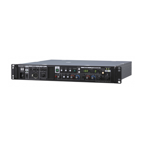
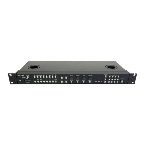
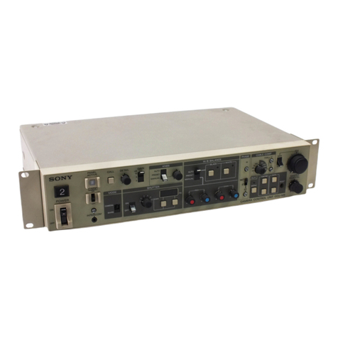
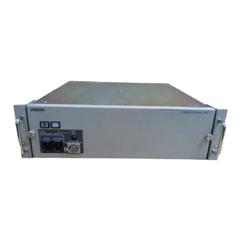
Sony HSCU300RF User manual

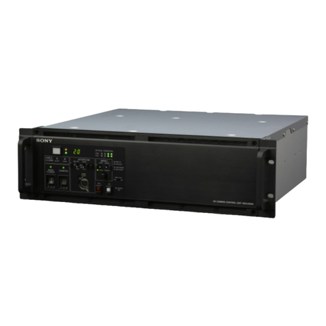
HD CAMERA CONTROL UNIT
HSCU300RF
HSCU300R
CCU CONTROL PANEL
HKCU-FP2
SERVICE MANUAL
1st Edition

警告
このマニュアルは, サービス専用です。
お客様が, このマニュアルに記載された設置や保守, 点検, 修理などを行うと感電や火災,
人身事故につながることがあります。
危険をさけるため, サービストレーニングを受けた技術者のみご使用ください。
WARNING
This manual is intended for qualified service personnel only.
To reduce the risk of electric shock, fire or injury, do not perform any servicing other than that
contained in the operating instructions unless you are qualified to do so. Refer all servicing to
qualified service personnel.
WARNUNG
Die Anleitung ist nur für qualifiziertes Fachpersonal bestimmt.
Alle Wartungsarbeiten dürfen nur von qualifiziertem Fachpersonal ausgeführt werden. Um die
Gefahr eines elektrischen Schlages, Feuergefahr und Verletzungen zu vermeiden, sind bei
Wartungsarbeiten strikt die Angaben in der Anleitung zu befolgen. Andere als die angegeben
Wartungsarbeiten dürfen nur von Personen ausgeführt werden, die eine spezielle Befähigung
dazu besitzen.
AVERTISSEMENT
Ce manual est destiné uniquement aux personnes compétentes en charge de l’entretien. Afin
de réduire les risques de décharge électrique, d’incendie ou de blessure n’effectuer que les
réparations indiquées dans le mode d’emploi à moins d’être qualifié pour en effectuer d’autres.
Pour toute réparation faire appel à une personne compétente uniquement.
Model Name Serial No.
HSCU300RF (SY): LEMO Opti-
cal Fiber Connector
10001 and Higher
HSCU300RF (SY): Tajimi Opti-
cal Fiber Connector
30001 and Higher
HSCU300R (UC): Kings Triax
Connector
10001 and Higher
HSCU300R (J): Tajimi Triax
Connector
30001 and Higher
HSCU300R (CED): Fischer Tri-
ax Connector
40001 and Higher
HSCU300R (CED): LEMO Tri-
ax Connector
60001 and Higher
HSCU300RF/HSCU300R

CAUTION
Use of controls or adjustments or performance of
procedures other than those specified herein may
result in hazardous radiation exposure.
For HSCU300RF only
CAUTION
The use of optical instruments with this product will
increase eye hazard.
For HSCU300RF only
This HSCU300RF is classified as a CLASS 1 LASER
PRODUCT.
For HSCU300RF only
HSCU300RF/HSCU300R

CAUTION
Danger of explosion if battery is incorrectly replaced.
Replace only with the same or equivalent type rec-
ommended by the manufacturer.
When you dispose of the battery, you must obey the
law in the relative area or country.
ATTENTION
Il y a danger d’explosion s’il y a remplacement incor-
rect de la batterie. Remplacer uniquement avec
une batterie du même type ou d’un type équivalent
recommandé par le constructeur.
Lorsque vous mettez la batterie au rebut, vous devez
respecter la législation en vigueur dans le pays ou la
région où vous vous trouvez.
VORSICHT
Explosionsgefahr bei Verwendung falscher Batterien.
Batterien nur durch den vom Hersteller empfohlenen
oder einen gleichwertigen Typ ersetzen.
Wenn Sie die Batterie entsorgen, müssen Sie die
Gesetze der jeweiligen Region und des jeweiligen
Landes befolgen.
注意
指定以外の電池に交換すると,破裂する危険があります。
必ず指定の電池に交換してください。
使用済みの電池は,国または地域の法令に従って
処理してください。
FÖRSIKTIGHET!
Fara för explosion vid felaktigt placerat batteri.
Byt endast mot samma eller likvärdig typ av batteri,
enligt tillverkarens rekommendationer.
När du kasserar batteriet ska du följa rådande lagar
för regionen eller landet.
PAS PÅ
Fare for eksplosion, hvis batteriet ikke udskiftes
korrekt.
Udskift kun med et batteri af samme eller tilsvarende
type, som er anbefalet af fabrikanten.
Når du bortskaffer batteriet, skal du følge
lovgivningen i det pågældende område eller land.
HUOMIO
Räjähdysvaara, jos akku vaihdetaan virheellisesti.
Vaihda vain samanlaiseen tai vastaavantyyppiseen,
valmistajan suosittelemaan akkuun.
Noudata akun hävittämisessä oman maasi tai
alueesi lakeja.
FORSIKTIG
Eksplosjonsfare hvis feil type batteri settes i.
Bytt ut kun med samme type eller tilsvarende
anbefalt av produsenten.
Kasser batteriet i henhold til gjeldende avfallsregler.
⊼ᛣ
⊼ᛣ
བᵰᤶⱘ⬉∴ϡℷ⹂ˈህӮ᳝⟚⚌ⱘ䰽DŽ
াᤶৠϔ㉏ൟࠊ䗴ଚ㤤ⱘ⬉∴ൟোDŽ
໘⧚⬉∴ᯊˈᖙ乏䙉ᅜⳌ݇ഄᆊⱘ⊩ᕟDŽ
HSCU300RF/HSCU300R

Table of Contents
Manual Structure
Purpose of this manual....................................................................................................................5
Related manuals...........................................................................................................................5
Trademarks...............................................................................................................................5
1. Service Overview
1-1. Location of Printed Circuit Boards............................................................................................1-1
1-2. Service Information...........................................................................................................1-2
1-2-1. Note on Replacement of Lithium Battery..............................................................................1-2
1-3. Flexible Card Wire............................................................................................................1-3
1-3-1. Connecting and Disconnecting Flexible Card Wires...................................................................1-3
1-3-2. Connecting and Disconnecting Flexible Card Wires with Connector..................................................1-3
1-4. Updating the Software Programs..............................................................................................1-5
1-4-1. Updating the Main Program ...........................................................................................1-5
1-4-2. Updating the BOOT Program..........................................................................................1-6
1-5. Writing and Rewriting the PLD Internal Data................................................................................1-7
1-5-1. Corresponding PLDs...................................................................................................1-7
1-6. Periodic Replacement Parts...................................................................................................1-9
1-7. Notes on Replacement of Circuit Board.....................................................................................1-10
1-7-1. EEPROM Data........................................................................................................1-10
1-7-2. Actions to Be Taken after Board Replacement/Repair................................................................1-10
1-8. Circuit Protection Parts......................................................................................................1-11
1-8-1. Circuit Protective Element............................................................................................1-11
1-8-2. Fuse....................................................................................................................1-11
1-9. Functions of Onboard Parts..................................................................................................1-13
1-9-1. Description of Onboard LED Indicators..............................................................................1-13
1-9-2. Functions of Onboard Switches.......................................................................................1-15
1-9-3. Functions of Onboard Potentiometers.................................................................................1-16
1-10. Cleaning of Connector/Cable................................................................................................1-17
1-10-1. When the Optical Connector Cleaner (Commercially Available) is Available.......................................1-17
1-10-2. When the Optical Connector Cleaner (Commercially Available) is not Available ..................................1-18
1-11. Circuit Description...........................................................................................................1-20
1-11-1. DM-152 Board (only in HSCU300R) ................................................................................1-20
1-11-2. ENC-112 Board (only in HSCU300R)................................................................................1-21
1-11-3. DPR-361 Board.......................................................................................................1-21
1-11-4. SDP-19 Board (only in HSCU300RF)................................................................................1-22
1-11-5. CN-3661 Board........................................................................................................1-23
1-11-6. CN-3662 Board........................................................................................................1-23
1-11-7. CN-3663 Board........................................................................................................1-23
1-11-8. AU-358 Board.........................................................................................................1-23
1-11-9. CN-3664 Board........................................................................................................1-23
1-11-10. PS-739D Board........................................................................................................1-23
1-11-11. CT-257D Board.......................................................................................................1-23
1-12. Lead-free Solder.............................................................................................................1-24
HSCU300RF/HSCU300R 1

2. System Setup
2-1. System Connection............................................................................................................2-1
2-2. Audio System.................................................................................................................2-2
2-2-1. Intercom System Setting................................................................................................2-2
2-2-2. Microphone Setting.....................................................................................................2-4
2-3. System Settings................................................................................................................2-6
2-3-1. Tally System............................................................................................................2-6
2-3-2. Camera Number Setting................................................................................................2-6
2-4. Video Signal System..........................................................................................................2-7
2-4-1. Input/Output Signal Selection..........................................................................................2-7
2-4-2. Signal Phase Adjustment...............................................................................................2-7
2-4-3. Aspect Ratio Setting for Down-Conversion............................................................................2-7
2-4-4. VBS Signal Level Adjustment........................................................................................2-10
2-4-5. Waveform Monitor Signal Level Adjustment.........................................................................2-10
2-4-6. Stair Case Signal Adjustment Procedure..............................................................................2-11
2-4-7. Picture Monitor Signal Level Adjustment............................................................................2-11
2-4-8. RETURN Input Signal................................................................................................2-12
3. Maintenance Mode
3-1. Preparations...................................................................................................................3-1
3-1-1. Starting/Exiting the Maintenance Mode................................................................................3-1
3-1-2. Memory Stick...........................................................................................................3-2
3-2. VE OPERATION Menu......................................................................................................3-3
3-3. MAINTENANCE Menu.....................................................................................................3-13
3-3-1. MAINTENANCE Menu (HSCU300RF).............................................................................3-13
3-3-2. MAINTENANCE Menu (HSCU300R)...............................................................................3-16
4. Replacement of Main Parts
4-1. General Information for Parts Replacement..................................................................................4-1
4-1-1. Index....................................................................................................................4-1
4-1-2. Tightening Torque......................................................................................................4-2
4-2. Top Cover.....................................................................................................................4-4
4-3. Front Assembly................................................................................................................4-5
4-4. ENC-112 Board (HSCU300R)................................................................................................4-6
4-5. DM-152 Board (HSCU300R).................................................................................................4-7
4-6. SDP-19 Board (HSCU300RF)...............................................................................................4-10
4-7. PS-739D Board..............................................................................................................4-12
4-8. TRIAX Connector Assembly (HSCU300R).................................................................................4-14
4-9. FL-378 Board (HSCU300R).................................................................................................4-15
4-10. FL-379 Board (HSCU300RF)...............................................................................................4-16
4-11. AU-358 Board...............................................................................................................4-17
4-12. CN-3664 Board..............................................................................................................4-18
4-13. DC Fan (HSCU300R)........................................................................................................4-19
4-14. DC Fan (HSCU300RF)......................................................................................................4-21
4-15. Rear Assembly (HSCU300R)................................................................................................4-23
4-16. Rear Assembly (HSCU300RF)..............................................................................................4-26
4-17. DPR-361 Board (HSCU300R)...............................................................................................4-28
4-18. DPR-361 Board (HSCU300RF).............................................................................................4-30
HSCU300RF/HSCU300R 2

4-19. Optical Multi Cable Assembly (HSCU300RF)..............................................................................4-32
4-20. CN-3661 Board..............................................................................................................4-34
4-21. CN-3662 Board..............................................................................................................4-35
4-22. CN-3663 Board..............................................................................................................4-36
5. Electrical Adjustment
5-1. Preparation....................................................................................................................5-1
5-1-1. Equipment Required....................................................................................................5-1
5-2. Audio System Adjustment....................................................................................................5-3
5-2-1. RTS Intercom Adjustment Check......................................................................................5-3
5-3. Video/Reference Signal System Adjustment..................................................................................5-5
5-3-1. 27 MHz VCO Free-Running Adjustment..............................................................................5-5
5-3-2. STAIR CASE Adjustment..............................................................................................5-6
5-4. SD Signal System Adjustment................................................................................................5-7
5-4-1. VBS Output Level Adjustment.........................................................................................5-7
5-4-2. PIX Output Level Adjustment..........................................................................................5-7
5-4-3. WF Output Level Adjustment..........................................................................................5-8
5-4-4. Y/R-Y/B-Y Output Level Adjustment (SD)............................................................................5-9
5-5. HD Signal System Adjustment..............................................................................................5-11
5-5-1. Y/R-Y/B-Y Output Level Adjustment (HD)..........................................................................5-11
5-5-2. RGB Output Level Adjustment.......................................................................................5-12
5-6. TRIAX Transmission System Adjustment...................................................................................5-14
5-6-1. 1.0-MHz Modulation Circuit Adjustment.............................................................................5-14
5-6-2. 1.4-MHz Demodulation Circuit Adjustment..........................................................................5-14
5-6-3. Tone Detection Frequency Adjustment...............................................................................5-15
6. Spare Parts
6-1. Note on Repair Parts..........................................................................................................6-1
6-2. Exploded Views...............................................................................................................6-2
6-3. Supplied Accessories........................................................................................................6-10
7. Diagrams
Block Diagrams.........................................................................................................................7-1
Frame Wiring...........................................................................................................................7-4
HSCU300RF/HSCU300R 3


Manual Structure
Purpose of this manual
This manual describes the information items that premise the service based on the block parts assuming use of system
and service engineers.
Related manuals
The following manuals are available in this model.
If this manual is required, please contact your local Sony Sales Office/Service Center.
• Operation Manual CD-ROM (Supplied with the unit)
This manual is necessary for application and operation of the unit.
• Installation Manual (Available on request)
This manual describes the information on installing this unit.
• Factory Service Manual (Available on request)
This manual describes the information items that premise the service based on the components parts.
Trademarks
Trademarks and registered trademarks used in this manual are follows.
• FRAM is a registered trademark of Ramtron International Corporation.
Other system names and product names written in this manual are usually registered trademarks or trademarks of
respective development manufacturers.
HSCU300RF/HSCU300R 5


Section 1
Service Overview
1-1. Location of Printed Circuit Boards
HSCU300R
HSCU300RF
HKCU-FP2
AU-358
CN-3661
CN-3662
CN-3663
CN-3664
DPR-361
CT-257D
DM-152
ENC-112
FL-378
FL-379
PS-739D
SDP-19
SW-1615
LED-525
AU-358
CN-3664
(AU-358:
Moving from the front panel
of the main body㸧
(CN-3664:
Moving from the front panel
of the main body㸧
CN-3661
CN-3662
CN-3663
DPR-361
CT-257D
PS-739D
HSCU300RF/HSCU300R 1-1

1-2. Service Information
1-2-1. Note on Replacement of Lithium Battery
A lithium battery is mounted on the DPR-361 board to backup the real time clock (RTC). If a battery comes to the
lifetime, then RTC stops. Therefore, replace the battery and re-set DATE/TIME on the C13 DATE page of the CCU
CONFIGURATION menu. (Refer to “Setup Menu” in the Operation Manual.)
Part No. Name Use
1-528-174-72 BATTERY, LITHIUM (CR2032
TYPE)
For real time clock (RTC) backup
CAUTION
In replacing, ensure that the battery is installed with “+” and “-” poles connected to the correct terminals.
Improper connection may cause an explosion or leakage of fluid.
HSCU300RF/HSCU300R 1-2

1-3. Flexible Card Wire
1-3-1. Connecting and Disconnecting Flexible Card Wires
Note
• Be very careful not to fold flexible card wires. Life of flexible card wire will be significantly shortened if it is folded.
• Each flexible card wire has conductive side and insulated side. If the flexible card wire is connected in the wrong
orientation of the conductive side and the insulated side, the circuit will not function.
• Insert the flexible card wire straight.
• Check that the conductive side of the flexible card wire is not contaminated.
A
Isolation
surface
(Type E)
A
Isolation
surface
(Type F)
Disconnecting
1. Slide or lift up the portion A in the direction of the arrow to unlock and pull out the flexible card wire.
Connecting
1. Slide or lift up the portion A in the direction of the arrow and securely insert the flexible card wire into the deep
end of the connector.
2. Return the portion A to its original position and lock the connector.
1-3-2. Connecting and Disconnecting Flexible Card Wires with Connector
Note
• Be very careful not to fold flexible card wires. Life of flexible card wire will be significantly shortened if it is folded.
• Check that the conductive side of the flexible card wire is not contaminated.
Conductive
side
Disconnection
1. Disconnect the flexible card wire while pushing both ends of the connector inside.
HSCU300RF/HSCU300R 1-3

Connection
1. Check the orientation of the conductive part and firmly insert the flexible card wire into the connector as far as it
will go.
HSCU300RF/HSCU300R 1-4

1-4. Updating the Software Programs
Software programs stored in the ROM on the DPR-361 board can be updating by using a Memory Stick.
For updating the software programs, follow the procedures below.
1-4-1. Updating the Main Program
Equipment Required
Memory Stick
Check
Check the current main program version with “ROM Version” of status display. (Refer to the Operation Manual.)
Preparation
Copy the updating program to the Memory Stick in the following steps.
Note
To get the updating program (program files “HSCU300R.rom” and “HSCU300R_BOOT.rom”), contact your local Sony
Sales Office/Service Center.
1. Make the following directory on the Memory Stick.
\MSSONY\PRO\CAMERA\HSCU300R
2. Copy the program files “HSCU300R.rom” and “HSCU300R_BOOT.rom” to the directory made in step 1.
Procedure
1. Turn on the power.
2. Insert the Memory Stick that contains the updating program into the Memory Stick slot on the rear panel.
Memory stick slot
Memory stick
3. Select VERSION UP EXEC from MAIN on the M02: Firmware Update page of the MAINTENANCE menu.
HSCU300RF/HSCU300R 1-5

4. A message “UPDATE MAIN BLOCK ?” appears. Turn the CANCEL/ENTER lever to the ENTER side.
DISP/MENU lever
CANCEL/ENTER lever
Control knob
(Rotary encoder)
5. Check that “LOADER BLOCK COMPLETE!!“ appears and then “MAIN BLOCK COMPLETE!!” appears.
6. Turn off the power and remove the Memory Stick.
7. When the unit is turned on, the main program is updated and runs.
8. Check that the main program has been updated with “ROM Version” of status display. (Refer to the Operation
Manual.)
1-4-2. Updating the BOOT Program
Equipment Required
Memory Stick
Check
Check the current boot program version with Firmware Update of the MAINTENANCE menu. (Refer to “3-3.
MAINTENANCE Menu”)
Preparation
Copy the updating program to the Memory Stick in the following steps.
Note
To get the updating program (program files “HSCU300R.rom” and “HSCU300R_BOOT.rom”), contact your local Sony
Sales Office/Service Center.
1. Make the following directory on the Memory Stick.
\MSSONY\PRO\CAMERA\HSCU300R
2. Copy the program files “HSCU300R.rom” and “HSCU300R_BOOT.rom” to the directory made in step 1.
Procedure
1. Turn on the power.
2. Insert the Memory Stick that contains the updating program into the Memory Stick slot on the rear panel.
3. Select VERSION UP EXEC from BOOT on the M02: Firmware Update page of the MAINTENANCE menu.
4. A message “UPDATE BOOT BLOCK ?” appears. Turn the CANCEL/ENTER lever to the ENTER side.
5. Check that version update is performed and a message “BOOT BLOCK COMPLETE!!” appears.
6. Turn off the power and remove the Memory Stick.
7. When the unit is turned on, the boot program is updated and runs.
8. Check that the boot program has been updated with Firmware Update of the MAINTENANCE menu. (Refer to the
“3-3. MAINTENANCE Menu”)
HSCU300RF/HSCU300R 1-6

1-5. Writing and Rewriting the PLD Internal Data
This unit is provided with PLD (Programmable Logic Device). They can be programmed and reprogrammed by the
MAIN program.
If the parts listed below needs to be replaced or if PLD needs to be updated, contact your local Sony Sales Office/Service
Center.
Note
The part number of PLD (or ROM for PLD) in which data is not written yet, is shown in “Spare Parts” of the Factory
Service Manual.
Therefore, if part replacement is required, write the data by the following procedure. In the case of the PLD type that
runs on the program stored in external ROM, the PLD has only to be replaced and data needs not to be written only.
1-5-1. Corresponding PLDs
Board name PLD ROM
DM-152 (HSCU300R) IC1701 IC1703
DPR-361 IC700 IC800
IC2000 IC2050
SDP-19 (HSCU300RF) IC100 IC407
Equipment Required
Memory Stick
Preparation
Copy the following ROM files to the directory created in the preparation process in “1-4-2. Updating the BOOT
Program”.
• tr-pld.rom (for HSCU300RF)
• sy-pld.rom
• post-pld.rom
• dm-pld.rom (for HSCU300R)
Procedure
1. Turn on the power.
2. Insert the Memory Stick that contains the ROM file for PLD into the Memory Stick slot on the rear panel.
3. Select a PLD to be programmed/reprogrammed from M03:PLD UPDATE of the MAINTENANCE menu.
Tip
If there are two or more target PLDs, they can be updated by “ALL” or “AUTO.” (Refer to “3-3. MAINTENANCE
Menu”)
4. When a message “XXX VERSION UP EXEC?” (XXX: PLD name) appears, press the ENTER key.
5. Confirm that the PLD has been updated and a message “PLEASE POWER OFF!!” appears.
6. Turn off the power and remove the Memory Stick.
7. When the unit is turned on, the PLD is updated and runs.
HSCU300RF/HSCU300R 1-7

8. Check that the main program has been updated with “SDP Diag”, “DPR Diag”, and “DM Diag” of status display.
(Refer to the Operation Manual.)
HSCU300RF/HSCU300R 1-8

1-6. Periodic Replacement Parts
This table does not describe the guarantee period of part.
The replacement period of each part depends on the environment and condition. Refer to “4. Replacement of Main
Parts” for the replacement method of parts.
Part name Part No. Check/replacement period
FAN, DC (60 SQUARE) 1-855-252-11 Replace every two years (When used for eight hours a day.)
HSCU300RF/HSCU300R 1-9

1-7. Notes on Replacement of Circuit Board
Note
After the following IC or the board has been replaced, check M01: SERIAL NO SET of the MAINTENANCE menu.
When the board status is shown as “NG”, execute WRITE. After that, confirm that “NG” changes to “OK”.
1-7-1. EEPROM Data
The table below lists data retained in the EEPROM on respective boards.
Note
The part number listed in “Spare Parts”of the Factory Service Manual is for EEPROM which is not programmed.
Therefore, program a new EEPROM after replacement. For details, contact your local Sony Sales Office/Service Center.
Board name Ref. No. Stored data
DM-152 IC1608 Board adjustment data
IC2201 Serial number, etc.
DPR-361 IC106 Serial number and board adjustment data
IC107 MAC address
SDP-19 IC105 Serial number, etc.
1-7-2. Actions to Be Taken after Board Replacement/Repair
Board name Action
DM-152 TRIAX Transmission System Adjustment (Refer to section 5-6.) *1
Setting of the cable length calculation reference value only when IC1608 is replaced *1
DPR-361 SD Signal System Adjustment (Refer to section 5-4.)
HD Signal System Adjustment (Refer to section 5-5.)
Re-setting of DATE/TIME after replacement of lithium battery
*1: Not necessary when the DM-152 board is replaced.
HSCU300RF/HSCU300R 1-10
Other manuals for HSCU300RF
1
This manual suits for next models
2
Table of contents
Other Sony Control Unit manuals
Popular Control Unit manuals by other brands

nvent
nvent Raychem NGC-40-BRIDGE installation instructions

Omnitron
Omnitron iConverter TM3 quick start guide

Siemens
Siemens SINAMICS G130 operating instructions

ADDAC System
ADDAC System T-Networks ADDAC103 Assembly guide

EVERSPRING
EVERSPRING AC301 user manual

VersaLogic
VersaLogic STD32 VL-1225 Reference manual

Yoshitake
Yoshitake GD-27BP product manual

Nibe
Nibe MODBUS 40 Installer manual

Inficon
Inficon IO1000 Translation of the original operating instructions

Ziton
Ziton ZPR868 Installation guide / instruction manual

Burkert
Burkert PTB 00 ATEX 2129 X operating instructions

urmet domus
urmet domus sinthesi S2 1748 quick start guide