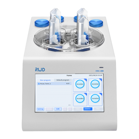
RWD MP-500 User manual

MP-500
Micropipette Puller
User Manual A

© 2021 RWD Life Science Co., Ltd. All Rights Reserved.
INTELLECTUAL PROPERTY RIGHT
The intellectual property rights of this product and its user manual are owned by RWD Life Science
Co., Ltd. (hereinafter referred to as RWD), including but not limited to patents, trademark rights, and
copyrights.
RWD reserves the right of final interpretation of this user manual.
RWD has the right to treat this user manual as confidential. Without the written permission of RWD,
no individual or organization should disclose this user manual, in whole or in part, by any means, nor
allow others or organizations to access the information of this user manual, in whole or in part, by
any means.
Without the written permission of RWD, no individual or organization should publish, modify, copy,
distribute, rent, adapt or translate this user manual into other languages, in whole or in part.
is the registered trademark or trademark of RWD. The trademark and related security
marks are intangible properties owned by RWD. The use of trademarks or marks not owned by RWD
in this user manual is for no other purposes except for editing, and the rights to them belong to their
respective owners.
STATEMENT
RWD reserves the right to modify this manual without prior notice.
RWD reserves the right to make changes in technology without prior notice.
RWD reserves the right to modify product specifications without prior notice.
RWD provides no guarantee in any form for this manual, including (but not limited to) the implied
warranty of merchantability and fitness for a particular purpose.
RWD considers itself responsible for the safety, reliability and performance of the device only if:
The assembly operations, expansion, readjustment, improvement and repair of this product are
performed by professionals approved by RWD;
The relevant electrical devices conform to the national standards;
The device is used by following the operating instructions.
RWD assumes no liability for the safety, reliability and performance of the product if:
The components are disassembled, stretched or re-debugged;
The device is repaired or modified by an unauthorized person of RWD;
The product fails to be used correctly according to the user manual.

Content
1-Introduction .................................................................................................................... 1
1.1 Overview ............................................................................................................................... 1
1.2 Safety .................................................................................................................................... 1
1.3 Product introduction .......................................................................................................... 1
1.4 Product Features ................................................................................................................. 2
1.5 Product Parameters ........................................................................................................... 3
1.6 Accessories ........................................................................................................................... 4
1.7 Device Conditions ............................................................................................................... 4
2-Important information and security ............................................................................ 5
2.1 Labels .................................................................................................................................... 5
2.2 Safety Cautions ................................................................................................................... 5
2.2.1 General safety ............................................................................................................... 5
2.2.2 Safety Instructions ....................................................................................................... 5
2.3-Safety Function ................................................................................................................... 6
3-Product interface and buttons ..................................................................................... 7
4-Operating Procedures.................................................................................................... 8
4.1 Initial start ............................................................................................................................ 8
4.2 Install glass ......................................................................................................................... 10
4.3 Softening point Test ......................................................................................................... 11
4.4 Edit Parameters ................................................................................................................. 13
4.5 Pull Protocol ...................................................................................................................... 13
4.6 Start and pause ................................................................................................................. 15
4.7 Program List ....................................................................................................................... 15
4.8 Remove microelectrode .................................................................................................. 16
4.9 Pull results .......................................................................................................................... 16
4.10 Preheat jaws .................................................................................................................... 17
4.11 Parameter adjustment ................................................................................................... 18
4.12 System Setting ................................................................................................................ 22
4.12.1 System diagnosis ..................................................................................................... 23

4.12.2 Help ........................................................................................................................... 25
4.12.3 System Maintenance ............................................................................................... 27
5-Troubleshooting ........................................................................................................... 29
6-Maintenance ................................................................................................................. 30
6.1 Overview ............................................................................................................................. 30
6.2 Cleaning and Maintenance .............................................................................................. 30
6.3 Replace filament ............................................................................................................... 30
6.4 Replace Drierite canister .................................................................................................. 35
6.5 General check .................................................................................................................... 37
6.6 Annual inspection ............................................................................................................. 38
7-Warranty ........................................................................................................................ 39

1
1-Introduction
1.1 Overview
First of all, thank you for choosing MP-500 Micropipette Puller made by RWD!
Please be sure to carefully read all the information attached before installing and using this
product for the first time, which will help you use the product better.
RWD Life Science Co., Ltd. is committed to continuously improving product functions and
service quality, and reserves the right to make changes to any product described in this manual
and the content of this manual without prior notice.
For the latest product information, please contact us by telephone or mail, or visit our website
(www.rwdstco.com). Please contact RWD if you find any inconsistency between the actual
product and the information contained herein during the use of the device, or when you have
any questions or suggestions.
Model: MP-500 Micropipette Puller
1.2 Safety
When operating the device, users should read the section
2-Important information and
security
to avoid injury to the operator and damage to the device during use.
If you have any questions or suggestions on safety, please contact us for after-sales service
support.
The device should be operated and managed by trained professionals!
This device is not intended for medical use. Microelectrodes pulled by
this device should be used only for animal experiments in a laboratory
environment, but not be applied on human bodies in any form.
1.3 Product introduction
The Micropipette Puller consists of a heating assembly, a pulley assembly and an air cooling
system. It can make a single capillary glass softened by high temperature heating and then
pulled into two glass microelectrodes with symmetrical tips. It is mainly used by experimental
operators for patch clamp experiments and microinjection operations in the laboratory
environment in universities, research institutions, hospitals and assisted reproductive

2
institutions, or used in various application scenarios that require micro-control operations in
industry.
User
Descriptions
Electrophysiology
researchers
From scientific research institutions, hospitals, pharmaceutical
companies and CROs, engaged in patch clamp and other
electrophysiological recording research, using glass
microelectrodes filled with electrolyte solution to collect weak
bioelectric signals such as ion channel current potential.
Microinjection
researchers
From various scientific research institutions and hospitals,
engaged in intracellular injection operation research (including
embryonic stem cell injection, intracytoplasmic sperm
injection, prokaryotic DNA injection, etc.).
Biological researchers
From various scientific research institutions and hospitals,
engaged in cell selection, collection, transfer and other
micromanipulations.
Application in industry
Preparation of liquid flow pipeline and liquid flow control
system in microfluidic chip technology, preparation of nozzles
in new printed circuit and 3D printing technology, preparation
of operating needles in cell cutting and capture systems, probe
production or preparation of particle capture needles in
material science.
1.4 Product Features
The user interface adopts capacitive color touch screen with high sensitivity.
The front panel cover adopts a roller design, which is convenient for users to open easily.
According to the type of capillary glasses and heating filaments and the type of
microelectrodes to be pulled (patch clamp microelectrodes, intracellular recording
microelectrodes, etc.), the corresponding pull protocol is provided as a reference and can
be modified according to special requirements.
The integrated plug-in humidity control chamber is easy to disassemble. The chamber can
keep the air around the filament and the capillary glass dry during the pulling process,
which can avoid the adverse effect of humid air on the pulling result.
The unique fixed position design of the heating filament makes it easier to replace various
models of filaments.
The one-button glass softening point test function is displayed directly on the main
interface for customer convenience.

3
The mechanical structure specially designed for the capillary glass makes the installation
and removal of the glass more convenient and safer.
The safe heat mode can avoid the damage of the filament from high temperature.
The preheating and constant temperature function can reduce the influence of the
accumulation of jaw heat on the consistency of the pulling results during continuous
pulling.
Two microelectrodes with symmetrical tips are stably produced every time. The diameter of
the tip can be less than 0.1 micron, the taper length 3-15 mm, and the impedance range
from 1 to above 100 megohm with high repeatability.
The system diagnostic function can be used to automatically check whether all components
of the puller are in normal working condition.
The copy-and-paste function makes it easier to copy existing programs.
The device can store up to 99 pulling programs.
1.5 Product Parameters
Parameters
Description
Display size
7-inch capacitive color touch screen
Display Pixels
1024×600 px
Device Size
530×355×278 mm(length×width×height)
Softening point
1-999
Pressure
1-999
Puff(s)
1-30
Cycles
1-10
Heat
1-999
Pull
0-255
Velocity
1-255
Cooling mode
Time mode (1-255), Delay mode (1-255)

4
1.6 Accessories
Configuration
Name
Quantity
Description
Standard
MP-500 Micropipette Puller
1
Main unit
Standard Power wire 1
Plug-in power wire for device
power input
Standard
Electrode storage box
1
For storing microelectrodes pulled
Standard Double-end screwdriver 1
To disassemble and assemble
accessories. One end is cross and
the other slotted.
Optional
HF-3025B、HF-3030B
HF-2545B heating filaments
3
For heating capillary glass. Users
can choose one for requirements.
Optional
6 kinds of cored glass:
B-15086-10F、B-10050-10F
、
B-10078-10F、B-12069-10F
、
B-12094-10F、B-150110-10F
6 boxes
For pulling microelectrodes. Users
can choose according to common
models.
Standard
Certificate of Inspection
1
/
Standard
Packing list
1
/
Standard
Easy Adjustment Guide
1
/
1.7 Device Conditions
Please prepare the device operating environment under the conditions listed in the table below
to ensure the operation and safety of the device.
Environment type
Description
Operating conditions
Temperature: 5-40 °C
Recommended laboratory temperature: 20-25 °C
Humidity: 10%-80% (non-condensing)
(10%-80% at 31 °C, 10%-50% at 40 °C)
Recommended laboratory humidity:
50%-80%
Storage conditions
Temperature: -20-60 °C
Humidity: 10%-93% (non-condensing)
Pressure: 50 kPa-106 kPa
Power
AC power: 100-240 V AC, 50/60 Hz; maximum power 150 W
Others
Avoid direct sunlight and rain; avoid severe vibration; the
altitude cannot exceed 2000 m; placed on a level and
stable platform

5
2-Important information and security
2.1 Labels
High temperature warning
Caution! High temperature!
Do not touch the heating filament and jaw with your hands. After pulling, wait for
the air pump to finish spraying and then gently pinch the end of the microelectrode
to remove it. Take care to avoid the tip of the microelectrode.
2.2 Safety Cautions
2.2.1 General safety
Please follow the instructions of all safety warnings and instruction labels on the device and
in the manual;
The device should be operated by trained professionals;
The device is only allowed to operate within its applicable scope, and only accessories
suitable for this device are allowed to be used. RWD shall not be responsible for any device
damage caused by any non-conforming operation, including the damage to a third party.
2.2.2 Safety Instructions
Radio interference For Class A equipment that emits radio interference specified in the EN
61326-1/EN 55011 Standard, this device is designed and tested in accordance with Group 1
Class A in CISPR11.
Warning!
Class A equipment is used in an industrial environment. Due to the conduction
disturbance and radiation disturbance of the equipment during use, it may be difficult to
ensure electromagnetic compatibility in other environments.
The device should be installed in a well-ventilated location, and the distance between the
device and the wall is at least 20 cm to ensure that the ventilation is not blocked;
The device should be kept away from the flammable and explosive locations;
To prevent the risk of electric shock, the power wire of this device can only be connected to
a grounded three-hole socket;
Do not put anything into the device from the gap, otherwise it may cause a fire or electric
shock. Do not spill any liquid on the device;

6
To prevent the risk of fire or electric shock, do not expose this device to rain or any type of
moisture;
Do not expose this device to direct sunlight;
Do not place heavy objects on the device;
Microelectrodes pulled by this device have sharp tips.
Please do not touch the tips with
your hands
;
Microelectrodes pulled should be placed in the attached electrode storage box to prevent
the tip of the microelectrode from collision and damage or to prevent dust particles from
entering the microelectrode and blocking the tips;
The microelectrode should be placed in sharp container and sealing for safety after use.
Do not disassemble this device. Only after-sales maintenance personnel designated by RWD
can disassemble the device or repair accessories.
2.3-Safety Function
The device is equipped with a low light transmittance cover covering the entire pulley
assembly, which can isolate the hazardous factors that may occur during the pulling
process, including the heat of the filament, dazzling light, and the rapid movement of the
clamping arm.
If the heating function is abnormal, the device will automatically turn off the power.

7
3-Product interface and buttons
Figure 3-1
Figure 3-2
No.
Components
Quantity
Description
①
Jaw
2
Install the filament
②
Drierite canister interface
2
Connect the Drierite canister
③
Capillary glass mounting brackets
2
Install the capillary glass
④
Red button
1
System restart
⑤
Green button
1
Multi-function button
⑥ Power switch 1
Turn on/off the main power
of the device
⑦
Power interface
1
Connect the power wire
⑧
USB port
1
System update interface
①
③
④
⑤
②
⑥
⑧
⑦

8
4-Operating Procedures
4.1 Initial start
This device should be placed on a stable and level platform during use. Do not place
on the unstable platform!
Connect the power wire, plug it into the three-hole socket, press the power switch to start the
device, and the system first displays the boot interface.
Figure 4-1
Wait 30s for the progress bar to load, enter the [Main Interface], as shown in Figure 4-2.
Figure 4-2

9
Parameters
Description
Softening point
The range of current value causing the filament generating enough heat
that can soften the glass is 1-999
Pressure (1-999)
The range of air pressure to cool glass and the heating filament is 1-999
Puff(s)
The reasonable range of duration of the humidity control chamber
being filled with dry gas at the beginning and the end of the pulling is
5-20 seconds
Safe heat
In order to avoid unstable pulling or burning the heating filament, the
heat cannot be lower or higher than 10% of the softening point
Time
The range of duration of puffing to cool the glass and the heating
filament during the pulling of the microelectrode is 1-255
Delay
The range of delay time of heating stop and pulling start is 1-255
Jaw temp
Display the current temperature of the jaw
Cycles
The number of heating cycles. The number of cycles per line ranges
from 1 to 10
Heat
The heat range of the heating filament is 1-999
Pull
The pulling force applied to both ends of the glass ranges from 0 to 255
Velocity
The velocity of pulling apart the glass ranges from 1 to 255

10
4.2 Install glass
Figure 4-3
No.
Parts
1
button
2
V-groove
3
Clamping knob
4
Puller bar handle
5
Clamping plate
6
Puller bar
1) Move the puller bars toward opposite directions to the end of their travels respectively until
they are caught to prevent them from sliding left and right;
2) First put the glass in the V-groove, turn the knob to fix the glass slightly, and note that the
glass can still be slid;
3) Press the buttons on both sides to release the puller bars, gently hold the puller bar handles
to pull both bars toward each other to the middle of the heating chamber;
4) Slightly loosen the knob, gently push the glass along the V-groove and make it carefully go
through the heating filament until the lengths of the glass on both bars L1 and L2 are
approximately equal; tighten the knob to complete the glass installation.
Note!
The glass must be close to the V-groove when sliding, otherwise the heating filament
may be damaged!
Note!
Do not use excessive force when pulling the bars and tightening the knob, otherwise
the glass may be broken!
2
L2
3
6
L1
5
4
1

11
Note!
When the microelectrode used in vivo microinjection, RWD recommends the model of
glass is B-15086-10F、B-10078-10F、B-12069-10F、B-150110-10F;
When the microelectrode used in patch clamp, RWD recommends the model of glass is
B-15086-10F、B-12069-10F、B-150110-10F、B-12094-10F!
4.3 Softening point Test
The heating assembly of this device increase the temperature of the heating filament via the
current to soften the glass. The softening point is the appropriate current value that can soften
the glass. Different types of heating filaments and glass vary in softening points. The device is
equipped with 3 types of heating filaments and 6 types of glass. Once the heating filament or
different types of glass are replaced, it is necessary to test the softening point and record it.
Note!
Once the heating filament or different types of glass are replaced, a softening point test
is required!
When the microelectrode used in vivo microinjection, RWD recommends the model of
heating filaments is HF-2545B!
1) Click on the [Main Interface] as shown in Figure 4-2 to enter the [Softening point test]
interface, as shown in Figure 4-4.
Figure 4-4
2) Press the green light button [START] on the right side of the display to start the test.

12
Figure 4-5
3) Get and record the softening point test value.
Figure 4-6
4) Click on the interface in Figure 4-6 to enter the [Softening point test]
interface as shown in Figure 4-4 and retest the softening point.
5) Click to enter the [Main Interface] shown in Figure 4-2, and the current
softening point test value will be automatically filled in the softening point input box.
6) It is recommended to repeat the test 3 times. The maximum value is the softening point.
Note!
After testing softening point, the glass will be broken. Please replace the glass before
pulling! Refer to
4.2 Install glass.

13
4.4 Edit Parameters
In the interface shown in Figure 4-7, each parameter can be edited.
Figure 4-7
4.5 Pull Protocol
In the [Main Interface], click to select the preset protocols of RWD for pulling.
1) Select the heating filament model. Heating filaments are all box-shaped. When the
microelectrode used in vivo microinjection, RWD recommends the HF-2545B filament.
Model
Specification(box length×width)
HF-3025B
3.0×2.5 mm
HF-3030B
3.0×3.0 mm
HF-2545B
2.5×4.5 mm
Figure 4-8

14
2) Select capillary glass.
Model
Specification(O.D.×I.D.×length)
B-15086-10F
1.5×0.86×100 mm
B-10050-10F
1.0×0.5×100 mm
B-10078-10F
1.0×0.78×100 mm
B-12069-10F
1.2×0.69×100 mm
B-12094-10F
1.2×0.94×100 mm
B-150110-10F
1.5×1.1×100 mm
Figure 4-9
3) Select the application of microelectrodes.
Figure 4-10
4) Finally, the system generates program parameters based on the above three options, and
the current protocol can be used as a new program or overwrite current parameters.

15
Figure 4-11
4.6 Start and pause
The green button [START/STOP] is a multi-function button, which can start or pause pulling; the
red button [RESET] can restart the system.
4.7 Program List
Click in the [Main Interface] as shown in Figure 4-2 to save the softening point
value and all current parameters.
Click on the [Main Interface] to view all saved programs. Up to 99 items can be
saved.
Figure 4-12
Double Click the selected program to open the program;

16
Click to create a new program, and enter the [Main Interface] to open a new program;
Click to copy the selected program parameters and enter the [Main Interface] to
open a new program;
Click to rename the selected program;
There are 6 factory setting programs in [Default program]. Click the selected program to open it
in the [Main Interface].
4.8 Remove microelectrode
After pulling, hold the end of the microelectrode with one hand, loosen the knob with the other
hand, and take out the microelectrode on both sides from the top of the V-groove.
Note!
The temperature of the newly pulled microelectrode is very high. Please do not
approach the heating chamber!
When removing the microelectrode, do not slide along the groove, otherwise the tip of
the microelectrode may be hit and damaged.
In order to avoid excessive microelectrode impedance caused by continuous
pulling and cool down the jaw temperature to a suitable range, wait for 1 minute
to start pulling again after the microelectrode is pulled!
4.9 Pull results
Click on the [Main Interface] to view each pull result of the microelectrode.
Figure 4-13
Table of contents
Other RWD Laboratory Equipment manuals
Popular Laboratory Equipment manuals by other brands

Micromeritics
Micromeritics SediGraph III 5120 Installation Instructions and Checklist

Hermle
Hermle Z 207 H user manual

Linkam Scientific Instruments
Linkam Scientific Instruments FDCS196 user guide

VWR
VWR avantor UHP user manual

KD Scientific
KD Scientific KDS LEGATO 100 user manual

Hach
Hach PHC201 user manual