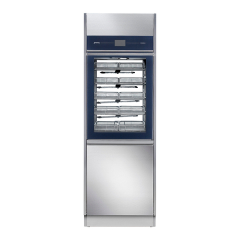
Smeg B-One User manual

B-One
STEAM STERILIZER
English user manual


B-One
STEAM STERILIZER
User manual
Dear Doctor,
We would like first and foremost to thank you for having selected a B-One autoclave.
Please note that the manufacturer is at your disposal for any further information and
explanations regarding this equipment.
We also would like to remind you that this manual must be read carefully before any
equipment use to ensure proper autoclave use.
Our products comply with current general safety norms and do not create hazards for
operators if used according to provided instructions.
Finally, we wish you success with your work and remind you that the reproduction of this
manual is strictly prohibited and that, due to our continued research and technological
developments, technical features of this equipment could be modified without prior notice.
Smeg Instruments

Revision n.1 User Manual B-One Edition: 04/2009 Page 4 of 52
READ THE INSTRUCTION MANUAL CAREFULLY
Failure to read this manual or any misunderstandings or erred interpretations of the
instructions contained within can cause damage to the equipment and could become
sources of danger for operators and notably reduce machine performance levels.
The manufacturer declines all responsibility for any use of this equipment differing
from uses described within this manual.
Any installation, maintenance and repair operations must be
performed solely by authorised Smeg personnel.
The warranty shall be forfeited any time the machine is
employed in a manner which has not be authorised by the
manufacturer.
The machine must only be used by specifically trained
person. It is Smeg task to train the designated users when the
machine is installed. Smeg declines all liability for
malfunctioning or accidents due to the machine having been
used by untrained persons.

Revision n.1 User Manual B-One Edition: 04/2009 Page 5 of 52
MANUAL CONTENTS
The purpose of this manual is to supply instructions for:
•correct installation
•safe and efficient equipment use
•continued and regular maintenance
Dimensions indicated in this manual are not binding.
All drawings and any other document contained in this manual are property of the
manufacturer, who reserves all rights its rights. Said drawings and documents cannot be
conferred to third parties.
Partial or complete reproduction of text or illustrations is strictly prohibited.

Revision n.1 User Manual B-One Edition: 04/2009 Page 6 of 52
INDEX
1PROPER USE ..............................................................................................9
2TECHNICAL FEATURES...........................................................................10
3INSTALLATION..........................................................................................12
3.1 INSTALLATION AND ELECTRICAL CONNECTION............................12
3.2 SAFETY WARNINGS...........................................................................13
4PRESENTATION........................................................................................14
4.1 FRONT DEVICES – CONTROL PANEL...............................................14
4.2 FRONT HYDRAULIC CONNECTIONS ................................................14
4.3 DEVICES ON THE REAR PANEL........................................................15
5MACHINE OPERATION.............................................................................16
5.1 GENERAL USER INTERFACE.............................................................16
5.2 TURN-ON .............................................................................................17
5.3 STERILIZATION CYCLE SELECTION AND START-UP......................17
5.4 AVAILABLE CYCLES – STERILIZATION AND TESTS........................19
5.5 PREHEATING.......................................................................................20
5.6 SHUTDOWN.........................................................................................21
5.7 RECOVERY AFTER A SUDDEN BLACK-OUT....................................21
5.8 TANK MANAGEMENT..........................................................................21
5.8.1 LOADING TANK FILLING - DEMI...................................................22
5.8.2 DEMINERALISED WATER QUALITY CONTROL..........................24
5.8.3 SUPPLY WATER QUALITY............................................................24
5.8.4 MANUAL DRAINING OF LOADING TANK WATER.......................25
5.8.5 WATER SUPPLY TANK DRAINING...............................................25
5.8.6 AUTOMATIC DRAINING ................................................................26
5.8.7 WATER PURIFIER WATER SUPPLY............................................26
5.8.8 AUTOMATIC SUPPLY FROM AN EXTERNAL CAN......................27
5.9 DOOR CLOSING..................................................................................27
5.10 CYCLE INTERRUPTION...................................................................28
5.11 CYCLE COMPLETED........................................................................29
5.12 PRINTER CONNECTION..................................................................29
5.13 FORCED INTERRUPTION................................................................30
5.14 USER RECOGNITION.......................................................................31
5.15 PASSWORD ENTRY PROCEDURE.................................................31
6SERVICE MENU - SETTINGS ...................................................................32
6.1 CYCLES ARCHIVE - INTERNAL AND MEMORY CARD.....................32
6.2 PREHEATING - WAKE.........................................................................34
6.3 LANGUAGE..........................................................................................34
6.4 DATE AND TIME..................................................................................34
6.5 DATE AND TIME FORMAT..................................................................35
6.6 PASSWORD.........................................................................................35
6.7 DISPLAY...............................................................................................36
6.8 SD MEMORY........................................................................................36
6.9 PRODUCT INFO...................................................................................36
6.10 MAINTENANCE.................................................................................36
6.11 SERVICE...........................................................................................36

Revision n.1 User Manual B-One Edition: 04/2009 Page 7 of 52
6.12 DOOR CLOSING...............................................................................37
7STEAM STERILIZATION...........................................................................38
7.1 RECOMMENDATIONS.........................................................................38
7.2 STERILIZATION MONITORING – B&D AND HELIX TESTS ...............38
7.3 PREPARATION OF OBJECTS FOR STERILIZATION.........................39
8ERRORS AND ALARMS ...........................................................................41
9MAINTENANCE .........................................................................................45
9.1 BACTERIOLOGICAL FILTER REPLACEMENT PROCEDURES.........45
9.2 MECHANICAL PARTS LUBRICATION ................................................46
9.3 MAINTENANCE OPERATIONS SUMMARY TABLE............................46
10 ACCESSORIES.......................................................................................47
10.1 PROVIDED ACCESSORIES .............................................................47
10.2 OPTIONAL ACCESSORIES UPON REQUEST ................................47

Revision n.1 User Manual B-One Edition: 04/2009 Page 8 of 52
GENERAL NOTES ON DELIVERY
Verify that packaging has not been damaged upon receipt of equipment.
Wait for a Service Assistance technician to open packaging and verify that supply
complies with order specifications and that there are no clear signs of damage. Promptly
inform Smeg S.p.A. or area representatives of any damage or missing parts. Do not
proceed with installation in case of said damage or missing parts.
The user is responsible for legal obligations related to correct installation and operation.
Smeg S.p.A. declines all responsibility for any failure or damage to third parties derived
from erred installation, improper use or lack of maintenance.
PACKAGING DIMENSIONS AND WEIGHT
The autoclave is delivered in packaging with the indicated dimensions and weight
fig. 1 – autoclave packaging, open bottom box which extraction from top
Approx. 52 x 60 x 70 [cm] – respectively width, height, depth
Net weight approx. 52 kg - Gross weight approx. 60 kg
TRANSPORT
B-ONE is supplied with packaging compliant with transport norms and with markings with
respect to product conservation and transport safety. We recommend keeping packaging
for any future equipment transfers or shipping.

Revision n.1 User Manual B-One Edition: 04/2009 Page 9 of 52
1 PROPER USE
B-One is a steam autoclave which can be used for the sterilization of medical and dental
instruments, in health or beauty centres and in veterinary practices.
As a small autoclave, this device is categorised as a class IIA medical device (according to
directive CE/93/42 classification criteria).
B-One carries out class "B" sterilization cycles, meaning cycles whose aim is to sterilize
packaged and unpackaged products, solids, products with a type A
1
hollow bodies and
porous products.
The fast cycle, named “FAST”, is dedicated solely to solid, unbagged instruments - this
cycle is not suitable for hollow bodies.
Test cycles to verify proper pneumatic system sealing and product operation efficiency
are also present.
Inner architecture
B-One has been designed with an innovative inner architecture: the sterilization chamber
is wound by an external chamber. The compartment between the two form a jacket in
which steam is present. This jacket is the essential element for autoclave performance and
efficiency.
B-One is also equipped with a steam generator connected directly to the jacket. A heating
element is housed in the generator.
Steam is produced by the generator and fills the jacket, therefore winding the sterilization
chamber and creating maximised temperature uniformity and stability conditions.
fig. 2 – Inner architecture: sterilization chamber, jacket, generator
1
Ref. NORM UNI EN13060: hollow bodies type "A" are intended as an open space with
one end where the ratio between length and diameter of the cavity is larger or equal to 1
and less or equal to 750 - or rather, a body with a length L on diameter D ratio so that:
1 ≤(L/D) ≤750 (or analogous open cavity at both ends such so that 2 ≤L / D ≤1500).

Revision n.1 User Manual B-One Edition: 04/2009 Page 10 of 52
2 TECHNICAL FEATURES
Manufacturer Smeg S.p.A.
Via Leonardo da Vinci, 4
42016 Guastalla RE - Tel. +39 0522 8211
Supply voltage 230V
Frequency 50 Hz
Max power input 1500W
Fuses on power input 2x10A 5x20 mm
Printer setup RS-232 serial port
Operating cycles 3 sterilization cycles
1 special prion cycle
Vacuum seal test and B&D test
Air filter Bacteriologic - porosity 0.3µm
Sterilization chamber dimensions 240 x 340 mm
External dimensions 48 x 44 x 60 cm (L x A x P)
Electrical resistance 1300W
Chamber capacity 4 standard trays (284x183x17)
Net weight 52 kg
Max weight (filled reservoirs and
maximum load in chamber) 62,5 kg
Net weight - Max weight (N/feet) 128 - 153 N/feet
Temperature range from 10°C to 40°C
Humidity
80% for temperatures up to 31°C with linear
decrease up to 50% at temperatures of
40°C
Altitude max 1000m
Max Noise emissions 66 db
Chamber – max pressure 2.6 bar
Generator and jacket – max pressure 2.6 bar

Revision n.1 User Manual B-One Edition: 04/2009 Page 11 of 52
REFERENCE NORMS
Product norm
UNI EN 13060
Safety norm
UNI EN 61010-1; UNI EN 61010-2-041
Directives
DIRECTIVE 93/42/CE “MEDICAL DEVICES”
DIRECTIVE 2004/108/CE “ELECTROMAGNETIC COMPATIBILITY”

Revision n.1 User Manual B-One Edition: 04/2009 Page 12 of 52
3 INSTALLATION
3.1 INSTALLATION AND ELECTRICAL CONNECTION
B-ONE is factory tested.
Product installation and maintenance must be performed by authorised Smeg
technical personnel.
Smeg declines all responsibility in the event of installation or maintenance
performed by unauthorised personnel.
Set B-One on a flat surface.
In addition to the external autoclave dimensions, consider an extra bulk in depth for
connections located on the rear side, approx. 6cm.
In the event of built-in installation, leave a suitable space on the sides and rear to allow
for equipment aeration, if possible leaving the rear part of the cabinet open. Do not set
equipment in areas with insufficient ventilation.
fig. 3 – Recommended values: A ≥
≥≥
≥1 cm, B ≥
≥≥
≥1cm
fig. 4 – D = 48 cm, E = 12cm. Recommended value: C ≥
≥≥
≥6 cm

Revision n.1 User Manual B-One Edition: 04/2009 Page 13 of 52
Do not install B-One next to sinks or other sources of humidity. Contacts with water can
generate short circuits and damage to electrical and electronic parts.
Keep equipment away from heat sources.
Make sure that the power supply cable is not bent and that nothing has been placed on
top of it and that the electrical socket can be easily reached. The cable is equipped with a
"schuko" type plug: do not use reducers or multiple sockets as they can cause
overheating.
The autoclave must be connected via protective switch to a system supplied with
earthing in compliance with current norm IEC 64-4. Make sure that the electrical capacity
of the system and electric connections are suitable for autoclave power. If necessary,
request a system check from qualified technicians.
Upstream installation a differential switch with the following is essential: rated current
10A; differential sensitivity 0.03A.
EN 61010-1 installation category (Class II)
Degree of pollution: 2
3.2 SAFETY WARNINGS
Do not use B-One in the presence of potentially explosive gas or vapours.
Do not pour water or other liquids on the equipment except in special connections for
demineralised water filling.
B-One carries out sterilization cycles during function, bringing B-One metal parts near the
chamber to high temperatures: be careful to prevent direct contact with the trays and
with other metal parts, use special supplied pliers.
Check that the power supply has been disconnected before any maintenance or control
intervention. If this is not impossible, disconnect the external network switch signalling
maintenance operations with a special sign in accordance with legal requirements
regarding safety in the workplace.
Do not tamper with labels or other identification signs on the equipment.
Smeg S.p.A. declines all responsibility for damage to property or persons derived from a
failure to observe the aforementioned instructions, in particular for a failure to verify the
suitability of the electrical system or any improper management of said system.

Revision n.1 User Manual B-One Edition: 04/2009 Page 14 of 52
4 PRESENTATION
fig. 5 - Front view of the autoclave, door open
4.1 FRONT DEVICES – CONTROL PANEL
Components on the control panel, located on the front right part of the machine
1. Display – communication component between the autoclave and user
2. “Turn and push” knob - to select and confirm selections
3. Bacteriologic filter from input air, replaceable
4. Analog gauge signals pressure present in the jacket winding around the
chamber.
5. “Memory card” housing – if the “memory card” (“SD” type) is present,
information related to sterilization cycles is registered on it
6. Main switch – equipment power supply.
4.2 FRONT HYDRAULIC CONNECTIONS
The three front hydraulic connections are accessible only when the door is open
1. Load connection demineralised water tank

Revision n.1 User Manual B-One Edition: 04/2009 Page 15 of 52
2. Discharge connection used water collection tank
3. Demineralised water tank discharge connection – said connection is
utilised when the loading tank needs to be emptied: in the event of maintenance or
tank emptying, if the tank has been filled with low quality water which is not suitable
for sterilization.
4.3 DEVICES ON THE REAR PANEL
fig. 6 - Rear view of the autoclave, lower right corner
In order, from top to bottom:
1. RS 232 port (printer or PC connection)
2. Switch for water purifier supply manual supply - standard: automatic – can
be set only by authorised technical personnel)
3. Power supply input cable
4. Quick connect for tank loading demineralised water from can (can only be
set by authorised technical personnel)
5. Quick connect for tank discharge of used water
6. Quick connect for DEMI-One water purifier loading

Revision n.1 User Manual B-One Edition: 04/2009 Page 16 of 52
5 MACHINE OPERATION
5.1 GENERAL USER INTERFACE
fig. 7 – Display and knob selection – on the upper right of the machine
The graphics display is the means by which the machine communicates with the user.
The display is 128 horizontal x 128 vertical pixels - it is monochromatic white and blue and
backlit.
The selectable items and icons on the display appear chromatically "inverted" when
selected to distinguish them from those which have not been selected.
fig. 8 - Stop” icon for a forced cycle stop, selected and unselected
The “turn-and-push” knob is the means by which the user communicates with the
machine: turn the knob to select items shown on the display, press to confirm selection.
A lit ring is housed on the knob. It shows different colours for different status (off, flashing,
fixed) depending on the current machine condition:
•
Fixed blue ring: machine ready for use
•
Flashing blue ring: cycle in progress
•
Fixed red ring: alarm compromising cycle implementation
•
Fixed violet ring: warning, operator intervention required (tank
filling/emptying, memory card insertion)
•
Ring off: machine off

Revision n.1 User Manual B-One Edition: 04/2009 Page 17 of 52
5.2 TURN-ON
The autoclave switches on when the ON/OFF button (blue general switch) is pressed. The
SMEG logo appears on the display and a BEEP sound will be activated.
The autoclave carries out a routine initial check. Any irregularities will be shown on the
display.
fig. 9 – Start-up screen – Smeg logo
Immediately following the initial check, the preheating phase starts. The main cycle
selection screen will appear on the display (see the following "preheating" paragraph for
further details).
fig. 10 – Main screen – cycle selection
It is also possible to select and confirm sterilization cycles during the preheating phase.
The machine will automatically manage the initial wait (approx. 15 min) and cycle start-up.
The vacuum test cycle does not need to wait until the end of the preheating phase to be
turned on.
5.3 STERILIZATION CYCLE SELECTION AND START-UP
Select the desired cycle from the main screen by turning the knob. Press the knob to
confirm cycle.
fig. 11 – Main screen
Once the desired cycle has been selected, the interface will request confirmation to
proceed.

Revision n.1 User Manual B-One Edition: 04/2009 Page 18 of 52
fig. 12 – Confirmation screen for selected cycle.
If the wrong cycle is selected, press "NO" on the display and you will return to the main
menu.
When "YES" is selected on the display, the machine will proceed and the user will be
asked to set the door for closing ("CLOSE DOOR" - see par. 5.9).
fig. 13 – Door closing request screen
It is still possible at this point to return to the main screen by selecting the "escape" icon
fig. 14 – “escape” icon– on the lower right of the display, this allows the user to return to the previous screen.
If the door is set for closing, B-One proceeds with automatic closing.
The display will read "cycle in progress".
In the event that the machine has not completed its preheating phase, the same screen
will however appear, but the preheating icon will appear flashing.
fig. 15 – “Cycle in progress” screen
The following information will be shown on the "cycle in progress" screen:

Revision n.1 User Manual B-One Edition: 04/2009 Page 19 of 52
Completed cycle sequence number (ex. “CYCLE N. 00029” image);
current cycle name (ex. “CLASS B 134 °C”);
chamber temperature (ex. “56.1 °C”)
chamber pressure (ex. “1.01 bar”);
instantaneous progress graphic with indication of time elapsed;
“lock” icon indicating the door status, locked:
preheating icon (if the icon image is not present, preheating has been completed);
“STOP” icon, for forced cycle interruption
5.4 AVAILABLE CYCLES – STERILIZATION AND TESTS
Available sterilization cycles:
•Class B 134°C
•Class B 121°C
•Fast 134°C
•Prion 134°C
2 test cycles:
•Vacuum test (auto vacuum seal test)
•B&D / helix test (class B auto-test)
The following table summarises sterilization cycle features.
Cycle Number
of
vacuums
Sterilization
temperature Sterilization
time Drying time
Description
121°C 16:00
CLASS B 4
134°C 4:00
9:00
Cycle for
sterilization of
turbines,
handpieces,
hollow bodies,
porous, double
bagged
FAST 3 134°C 4:00 2:00
Cycle for
sterilization of
solid,
unbagged
instruments,
not suitable for
hollow bodies,
type N
PRION 4 134°C 22:00 9:00 Prion cycle

Revision n.1 User Manual B-One Edition: 04/2009 Page 20 of 52
Vacuum test: cycle for autoclave pneumatic seal verification (duration approx. 16 min). A
vacuum and electronic controls verify pneumatic seal efficiency in the sterilization
chamber.
B&D / Helix test: cycle for sterilization efficiency verification, cycle parameters analogous
to those used in the “CLASS B 134°C” cycle but with 3.5 minutes of sterilization time and
limited drying. To be performed together with related system tests.
5.5 PREHEATING
Preheating requires that the machine be brought to a useful temperature range for starting
a sterilization cycle.
In this phase, the heater in the steam generator is activated.
Once useful conditions are reached, resistance start-up is modulated to keep the machine
ready for use for a period of approx. 1 hour.
The preheating phase is immediately active upon machine turn-on (the turn-on time, or
"wake", can also be programmed - see the "SETTINGS-WAKE" paragraph).
It is possible to turn on a sterilization cycle (or test) even if preheating has not been
completed. In this case, sterilization will require additional preheating time, managing the
wait time automatically.
fig. 16 – “"preheating" icon
The "preheating" icon appears on the lower right side of the display to indicate preheating
status
If the icon is flashing, preheating is in progress.
If the icon does not appear, the machine is ready and jacket temperature has
reached a suitable level for immediate cycle turn-on.
After a certain period without use, approximately 1 hour, the machine will enter into
energy saving or “stand-by” mode. In this phase, the heater will not be activated. The
chamber, jacket and generator temperatures will gradually decrease over time.
It is possible to select and activate a sterilization cycle even from the stand-by mode. The
machine will then restart preheating and will autonomously manage cycle turn-on.
Table of contents
Other Smeg Laboratory Equipment manuals