1
Lawnaire
IV & V
2-2007
IMPORTANT MESSAGE
Thank you for purchasing this Schiller Grounds Care, Inc.product. You have purchased a world class product,
one of the best designed and built anywhere.
This machine comes with a Technical Manual containing safety, operation, parts, maintenance and service
information. The useful life and good service you receive from this machine depends to a large extent on how
well you read and understand this manual. Treat your machine properly, lubricate and adjust it as instructed,
and it will give you many years of reliable service.
Your safe use of this Schiller Grounds Care, Inc.product is one of our prime design objectives. Many safety
features are built in, but we also rely on your good sense and care to achieve accident-free operation. For best
protection, study the manual thoroughly. Learn the proper operation of all controls. Observe all safety precau-
tions. Follow all instructions and warnings completely. Do not remove or defeat any safety features. Make sure
those who operate this machine are as well informed and careful in its use as you are.
See a Schiller Grounds Care, Inc.dealer for any service or parts needed. Schiller Grounds Care, Inc.service
ensures that you continue to receive the best results possible from Schiller Grounds Care, Inc.products. You
can trust Schiller Grounds Care, Inc.replacement parts because they are manufactured with the same high
precision and quality as the original parts.
Schiller Grounds Care, Inc.designs and builds its equipment to serve many years in a safe and productive man-
ner. For longest life, use this machine only as directed in the manual, keep it in good repair and follow safety
warnings and instructions. You'll always be glad you did.
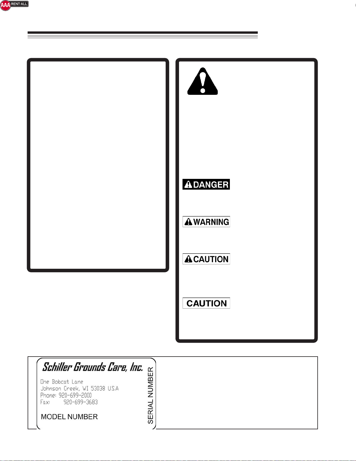
Schiller Grounds Care, Inc.
One Bob Cat Lane
Johnson Creek, WI 53038-0469
TABLE OF CONTENTS FIGURES PAGE
SAFETY............................................................................................................................................................2
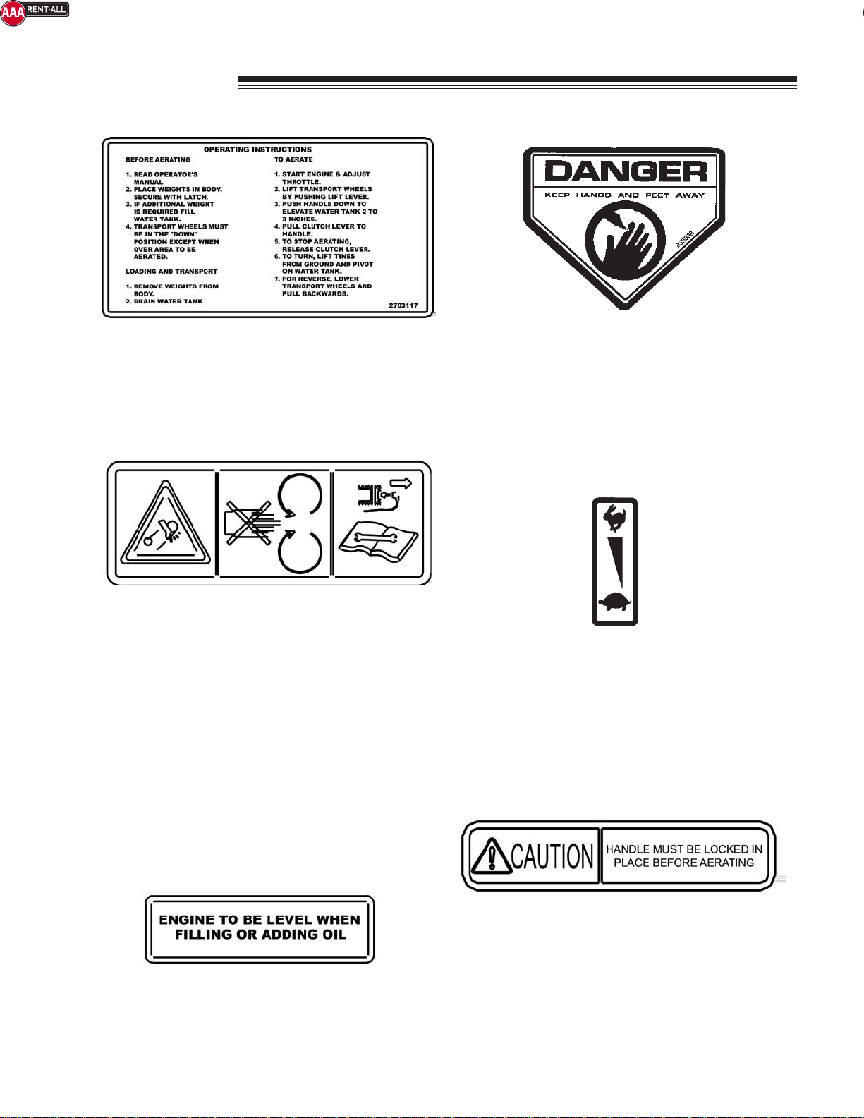
SAFETYAND OPERATION DECALS..............................................................................................................3
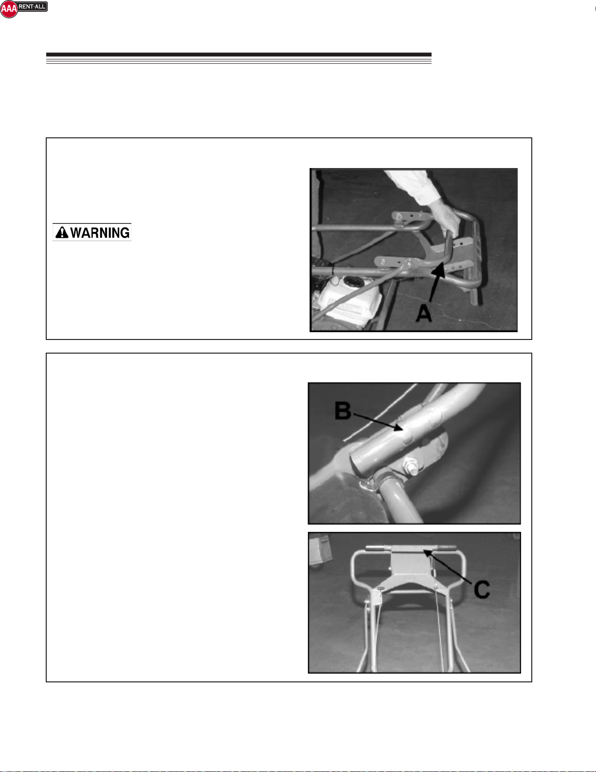
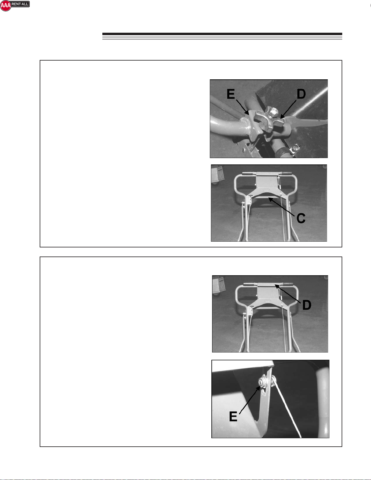
ASSEMBLY/SET-UP INSTRUCTIONS ........................................................................................................4, 5
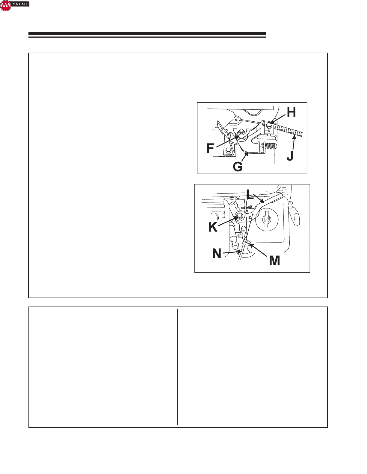
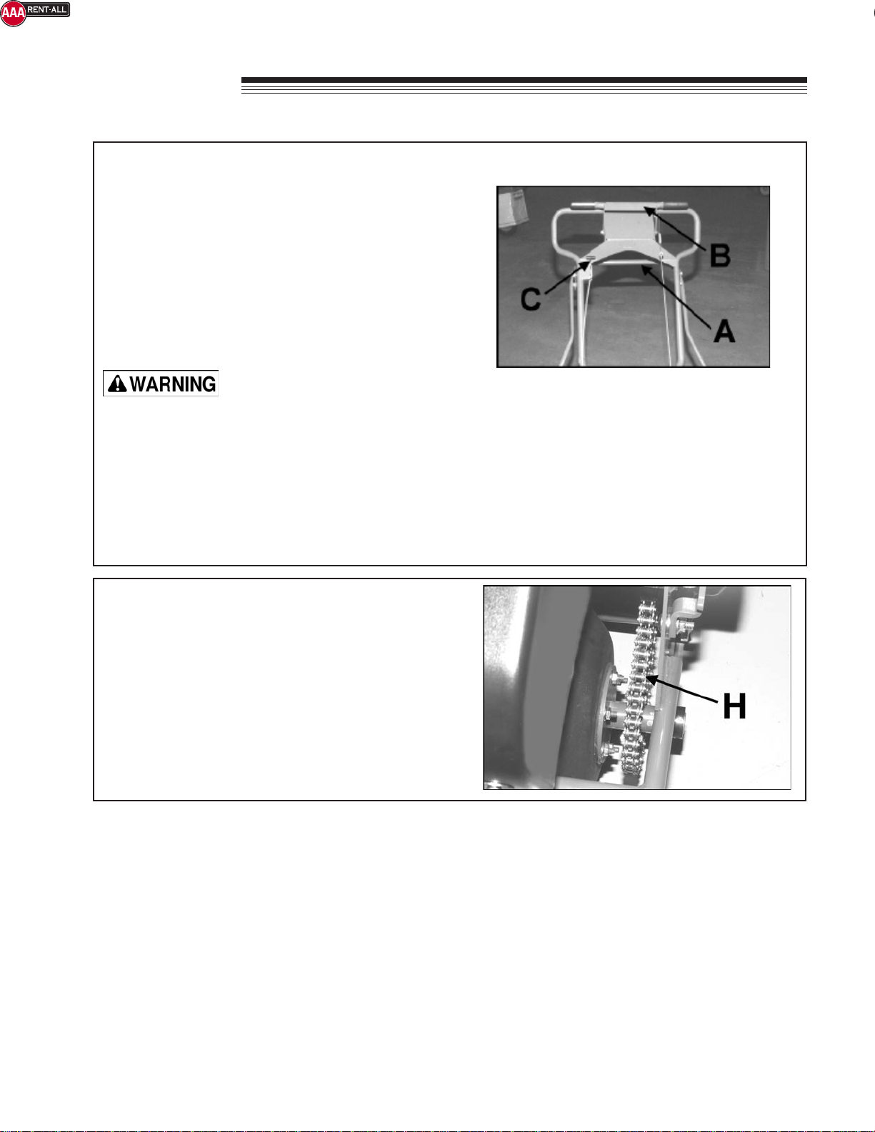
CONTROLS..................................................................................................................................................7, 8
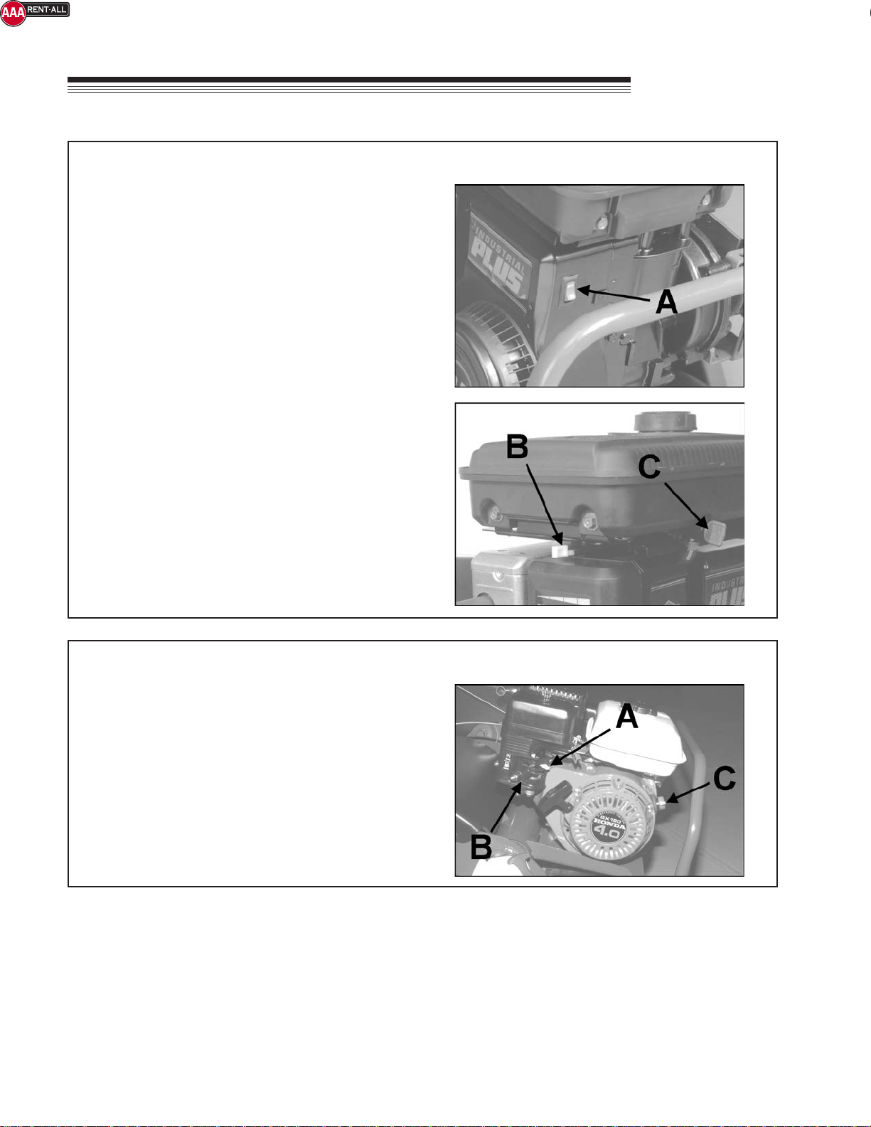
OPERATION...............................................................................................................................................9, 10
SERVICE........................................................................................................................................................11
STORAGE......................................................................................................................................................12
TRANSPORTING...........................................................................................................................................13
SPECIFICATIONS..........................................................................................................................................14
PARTS SECTION...........................................................................................................................................15
FRAME GROUP .............................................................................................FIGURE 1.......................... 16, 17
MAIN GROUP-LAWNAIRE IV.........................................................................FIGURE 2........................... 18, 19
MAIN GROUP-LAWNAIRE V..........................................................................FIGURE 3........................... 20, 21
HANDLE GROUP............................................................................................FIGURE 4........................... 22, 23
TINE WHEEL GROU.......................................................................................FIGURE 5.......................... 24, 25
DRUM GROUP................................................................................................FIGURE 6 .......................... 26, 27
DECAL GROUP-LAWNAIRE IV.......................................................................FIGURE 7.......................... 28, 29
DECAL GROUP-LAWNAIRE V........................................................................FIGURE 8.......................... 30, 31
*Call AAA Rent-All at 225-291-1356 for assistance ordering parts*