Ryf AG 66/40 User manual

LED ILLUMINATION
OPERATING INSTRUCTION
Ryf AG
Bettlachstrasse 2
2540 Grenchen
tel 032 654 21 00
fax 032 654 21 09
www.ryfag.ch

(A) 5 Plug for 4
7 Fixing screw
(B) 5 Plug for 4
6 Gooseneck
(C) 8 Plug for mainscable
9 Plug for 3
(D) 1 On-Off Switch
2 Brightness control
3 24 V power supply
4 A/B Port A/B for spot/ringlight
10 DSE connectors
12 segment switch
13 segment rotation
(E) Backlight
(A)
757 5
(B) (C)
658 9
1 2 12 2 13 4A 10 4B 3
(D)
(E)

English
OPERATING INSTRUCTIONS FOR LED ILLUMINATION UNIT
DESCRIPTION
This new type of LED illumination device (Light Emitting Diode) has been
developed for stereomicroscopy illumination purposes in industrial and labor-
atory settings.
Please use the diagrams on the left-hand cover of this operating manual.
In purchasing this product, you have acquired a high-quality LED illumination
unit for all applications requiring intensive light with minimal heat generation.
LEDs are employed as the illuminant.
The following features are characteristic of this type of illumination:
TColor temperature 5,000 K (daylight!)
TRipple and flicker free
TLong LED lifetime
TQuiet operation, free of vibration
TExtremely compact design
TBattery operation possible
The modular design of the LED illumination device in combination with the
TRinglight – provides homogeneous shadow-free illumination
TSpot – provides directional illumination
TBacklight – provides homogeneous illumination which passes the object
The illumination system consists of:
T(Desktop) power-supply
TControl unit and
TLED unit (1 ringlight 66/40 or 1 or 2 spots or backlight or ringlight 38/20)
The power-supply (C) voltage range extends from 100–240 V and features a
3-pin plug connector.
The compact control unit (D) has an On/Off switch (1), a continuously adjust-
able brightness control (2) with a „turbo range“ and two connector plugs (4) for
connecting the LED illumination units.
A 24 V battery or an accumulator can be attached to the control unit via a
special cable by means of the hollow plug connector (3).
The LED ringlight (40 LEDs) (A) allows surfaces to be illuminated exceptionally
brightly and homogeneously and fits all microscopes with an objective diameter
of 66 mm. Adapters are available for use with other microscopes. The ringlight
is attached by means of a spring and screw, thereby protecting the objective.
The LED spot (19 LEDs) (B) can be attached directly to the microscope using
a goose neck (6) or can be positioned as required using the goose neck and a
base plate.
A wide range of accessories allows this LED illumination to be used for many
purposes.
The LED backlight (20 LEDs) (E) can be used instead of the microscope’s object
holder to illuminate transparent objects from the bottom.
Please read all the operating instructions before operating the LED illumination unit!
Technical data
LED ringlight 66/40 LED ringlight 66/80 LED ringlight 38/20
Diodes 40 white LEDs 80 white LEDs 20 white LEDs
Color temperature 5,000 K 5,000 K 5,000 K
Dimensions outer: Ø94x25 outer: Ø 112 x 23.5 mm outer: Ø60x25mm
inner: Ø 66 mm inner: Ø 66 mm inner: Ø 38 mm
Attachment Circumferential clamp with spring and screw
LED spot LED backlight
Dioden 19 white LEDs 20 white LEDs
Farbtemperatur 5,000 K 5,000 K
Dimension Ø 34 mm x 45 mm
Attachment using goose neck
Carrier plate PVC black, Ø 120 mm x 24.5 mm
Object holder compound glass, Ø 95 mm
Illuminated surface Ø55mm
Control unit Standard Segment (40 LED) Segment (80 LED)
Supply 24VDC+/–5%,hollow plug 5.5 x 2.1 mm
250 mA 250 mA 500 mA
Dimension 95.5 x 64 x 29 mm 95.5 x 64 x 29 mm 102 x 106 x 39 mm
Connectors for ringlight/spot 2 x 9-pin miniature DIN socket 2 x 9-pin miniature DIN socket D-Sub (25 pin)
On/Off switch On/Off with segment selector with segment selector
Button for segment rotation – 1 2
Potentiometer wheel 3–30 mA, with index holes
ESD connection 4 mm banana connector
Operating ambient temperature 10–40 °C (*)
Rel. humidity 30–70 %
Mark of conformity CE
Power supply
Plug connector 3-pin IEC 320
Voltage range 100–240 V
Mains frequency 50–60 Hz
Power rating max. 15 VA
Protection class I
Mark of conformity CE, UL, CSA
(*) LEDs are suitable for use at temperatures up to 40 °C. However, increasing temperature and humidity results in a reduction in lifetime. For optimal use, the ambient temperature should be 25 °C (or
lower) and the relative humidity 50 % (or lower).
CE Mark of conformity: Certifies that the control unit conforms to the EMC directive 89/336/EEC

Two danger symbols are used throughout this document.
Caution: Risk of electrical shock
Caution: Dangerous area.
Warning: Refer to accompanying documentation.
This section contains safety information which must be observed
strictly when using this device.
IT IS IN YOUR OWN INTERESTS TO PAY ATTENTION TO ALL WARNINGS on the
unit and in this manual.
Target audience
People working with the device must read the sections which are relevant to
their work. This applies especially to the chapter entitled “Safety information”.
Duty of observation with respect to product
The operator must report all operational irregularities or changes to componen-
ts which are relevant to device safety immediately to the responsible supervisor
or the manufacturer.
Location of operating instructions
We recommend storing these operating instructions near the device to ensure
quick access by operating staff.
Legal provisions
National and local safety and accident prevention regulations which are in force
must be strictly observed in addition to the operational guidelines issued by the
operating entity.
Do not make any technical modifications to the device under
any circumstances!
Refer to specifications in “Technical Data” section for binding operational
limits.
DO NOT USE this unit near water or in any area with excessive moisture.
WARNING: In order to prevent electric shock, do not expose this appliance to
rain or high humidity.
NEVER SPILL LIQUID ON THE UNIT OR INSERT OBJECTS INTO THE UNIT! This
could result in electric shock or damage to the unit.
DO NOT PLACE FLAMMABLE MATERIALS on or near the unit at any time. Keep
unit AWAY from other sources of HEAT. The device has not been approved for
operation in areas subject to explosion hazards!
The device may only be operated using the mains voltage indicated.
NEVER OPEN THE APPLIANCE OR ANY COMPONENTS, unless instructed
expressly to do so by these instructions.
Never look directly at the LEDs when switched-on, otherwise you risk
eye injuries.
Cleaning
Disconnect unit from the mains power supply before cleaning and only clean
with a damp cloth. Never use combustible or flammable liquids. If fluids acci-
dentally enter the device, unplug the mains cable and let the unit dry thoroughly
before using again.
Spare parts
Use only original spare parts. If this is not done, it can lead to personal injury
and material damage. Refer to “Spare Parts” section for component codes.
Responsibility
As the ultimate legal entity, the operating institution is responsible for ensuring
the proper use of the device and for providing other operators with the necessary
information and it specifies the competencies required to operate the device.
DISCONNECT THE MAINS CABLE when the unit is not being used for an extended
period of time.
ONLY USE THE ORIGINAL MAINS CABLE. Route cable so that it cannot be jammed
or severed.
FOR REASONS OF SAFETY only use the grounded 3-pin plug.
Repairs which are not described in this document must only be carried out by
authorized workshops!
The manufacturer is not liable for any damage resulting from a failure to comply
with the above instructions!
Current technology
Photonic LED illumination devices constitute state-of-the-art technology and
employ recognized safety standards.
This instrument was designed and built in accordance with the following
regulations and standards:
TEEC/89/336: Electromagnetic compatibility (CE)
TISO 9001/2: Quality systems for development and production
SAFETY INFORMATION

Remove the individual system components from their packaging and place them
onto a horizontal surface.
To obtain optimal functionality, the LED illumination system must be positioned
correctly.
Observe the following criteria:
TNo high atmospheric humidity (cf. Technical data)
TNo high room temperature (cf. Technical data)
The device may only be operated at the rated mains voltage. Only con-
nect the unit to grounded sockets.
Keep air vents free!
The control unit must only be operated with the power-supply provided!
Connect one end of the power-supply to the control unit (3) (24 V DC input) by
means of the hollow plug connector (9) and the other end to the power mains
(100–240 V AC, 50–60 Hz) by means of the mains cable (8). If necessary, use the
ESD connector (10) for potential equalisation.
Plug the LED lighting into the control unit. Only use Port A of the
control unit for the LED ringlight 66/40 (and all future products with 40
LEDs). LED spot, backlight and ringlight 38/20 can be used on Port A and/or B.
The following possibilities are available with the two Ports A and B (4) of the
control unit:
T1 LED ringlight 66/40 on Port A
T1 or 2 LED spots or LED backlights or LED ringlights 38/20 on Port A and B
The LED ringlight can now be mounted directly onto the objective of all micro-
scopes with 66 mm diameter by means of a clamping ring which does not
damage the surface of the objective. For objectives with any other diameter
there is a wide range of adapters available.
For mounting the LED spot, “goosenecks” (6) of different lengths and threads
are available, allowing the LED spot to be pointed in any desired direction.
The one end (with the O-ring) of the gooseneck is inserted into the opening of
the LED spot. The other end can be screwed directly onto the microscope or
optionally into a base plate.
The LED illumination unit can be switched on and off (Position I: On; Position 0:
Off) using the switch located on the control unit (1).
The potentiometer wheel (2) is used to control the brightness, with the cur-
rent being adjustable from 3 mA to 30 mA. Please note that the current level
influences not only the brightness, but also the service life of the LEDs.
The approximate potentiometer wheel setting can be read from the scale on the
wheel.
Minimum (3 mA) 10 mA 20 mA Maximum (30 mA)
View of standard control unit
View of control unit with segment control
The following segments can also be selected with the on/off switch:
TSemicircle
TQuarter circle
T2 opposing quarter circles
This segment selection can be rotated using (13).
Do not open the unit or its individual components.
Lifetime
LED chips have a typical lifetime of about 100.000 hours. The actual service
life depends to a great extent upon the ambient temperature and the operating
current of the LEDs. A higher operating current produces not only more light but
also more heat, which reduces the life span of the LEDs.
As a rule, the brightness of LEDs also decreases over the life cycle. After about
7000 hours at the highest possible luminance – i.e. at the potentiometer wheel
“turbo” setting – the brightness will drop by 50 %. On the other hand, the same
value will be reached in the 10 mA position only after 20,000 hours service. This
figure increases substantially with a setting below 10 mA.
To increase the lifetime of the LEDs, the brightness should be adjusted to the
actual level required at any point in time.
Faulty LEDs can be replaced. Contact your dealer or the manufacturer with
respect to this matter.
INSTALLATION AND CONNECTION OPERATION
English

Component description Article number
Power supply 100–240 V AC, 24 V DC/15 W 302 11 002
Control unit (max. 40 LED) 302 11 001
Control unit with segment control (max. 40 LED) 302 11 004
Control unit with segment control (max. 80 LED) for ringlight 66/80 only 302 11 005
LED ringlight 66/40 (40 LEDs) 302 10 004
LED ringlight 66/80 (80 LEDs) 302 30 002
LED ringlight 38/20 (20 LEDs) 302 30 001
LED spot (19 LEDs) 302 20 001
LED backlight (20 LEDs) 302 40 001
Gooseneck for spot M5 – 85 mm 302 21 005
Gooseneck for spot M5 – 200 mm 302 21 006
Gooseneck for spot M5 – 300 mm 302 21 007
Blue filter for spot 302 21 001
Green filter for spot 302 21 002
Yellow filter for spot 302 21 003
Red filter for spot 302 21 004
Base plate with M5 adapter for gooseneck 302 21 008
Polarization filter set for LED ringlight 66/40 302 31 001
Clamping ring for LED ringlight 66/40 + 66/80 301 22 102
Clamping ring screw for ringlight 302 31 002
LED ringlight adapter for:
Objective 66/58 mm 595-32-258
Olympus SZ III, SZ 60, SZ 1145 598-30-002
Olympus SD, SF, SZ with lens attachment 598-30-017
Olympus SZH, SZX9, SZX12, Nikon SMZ 800, SMZ/U, 10A, 1000, 1500 598-32-043
Nikon (except for SMZ-1) 598-30-004
Olympus SD, SF, SZ without lens attachment, Nikon SMZ-1, 1B, 2B, 2T 598-32-049
Nikon SMZ 645 + SMZ 660 598-32-050
Universal adapter for diameters from 38 mm to 58 mm 598-30-022
Adapter DM38 / DM36 mm 619-32-056
Mains cable, 3-pin IEC320 for:
EU 301 17 104
CH 301 17 105
IT 301 17 103
UK 301 17 106
USA/CAN/J 301 17 102
AUS 301 17 107
SPARE PARTS AND ACCESSORIES
Article number
ENSS-15.001
619-30-001
619-30-021
619-30-022
619-20-002
619-20-035
619-20-006
619-20-011
619-20-032
619-30-003
619-30-004
619-30-005
619-30-010
619-30-011
619-30-012
619-30-013
619-30-007
619-20-021
595-32-013
619-30-008
595-32-258
598-30-002
598-30-017
598-32-043
598-30-004
598-32-049
598-32-050
598-30-022
619-32-056
ELN-3.001
ELN-3.002
ELN-3.009
ELN-3.004
ELN-3.003
ELN-3.006

The design of the product is under constant review, and although every effort
is made to keep this manual up to date, we reserve the right to change
specifications at any time without prior notice. Not responsible for typografical
and misprint errors.
English

(A) 5 Stecker für 4
7 Klemmschraube
(B) 5 Stecker für 4
6 Schwanenhals
(C) 8 Stecker für Netzkabel
9 Stecker für 3
(D) 1 Ein/Aus-Schalter
2 Helligkeitsregelung
3 24-V-Versorgung
4 A/B Stecker A/B für Spot/Ringlicht
10 ESD-Stecker
12 Segmentschalter
13 Segmentrotation
(E) Durchlicht
(A)
757 5
(B) (C)
658 9
1 2 12 2 13 4A 10 4B 3
(D)
(E)

Deutsch
Bitte lesen Sie vor Inbetriebnahme der LED-Beleuchtung die komplette Bedienungsanleitung!
Technische Daten
LED-Ringlicht 66/40 LED-Ringlicht 66/80 LED-Ringlicht 38/20
Dioden 40 Stück weiße LEDs 80 Stück weiße LEDs 20 Stück weiße LEDs
Farbtemperatur 5.000 K 5.000 K 5.000 K
Dimensionen außen: Ø 94 x 25 außen: Ø 112 x 23,5 mm außen: Ø 60 x 25 mm
innen: Ø 66 mm innen: Ø 66 mm innen: Ø 38 mm
Befestigung Umfangklemmung mittels Feder und Schraube
LED-Spot LED-Durchlicht
Dioden 19 Stück weiße LEDs 20 Stück weiße LEDs
Farbtemperatur 5.000 K 5.000 K
Dimension Ø 34 mm x 45 mm
Befestigung mittels Schwanenhals
Trägerplatte PVC schwarz, Ø 120 x 24,5 mm
Objektträger Verbundglas, Ø 95 mm
Ausgeleuchtete Fläche Ø 55 mm
Steuereinheit Standard Segment (40 LEDs) Segment (80 LEDs)
Versorgung 24 V DC +/– 5 %, Hohlstecker 5,5 x 2,1 mm
250 mA 250 mA 500 mA
Dimension 95,5 x 64 x 29 mm 95,5 x 64 x 29 mm 102 x 106 x 39 mm
Anschlüsse für Ringlicht /Spot 2 Stück 9-polige Mini-Din-Buchse 2 Stück 9-polige Mini-Din-Buchse D-Sub (25 pin)
Ein/Aus-Schalter Ein/Aus mit Segmentauswahl mit Segmentauswahl
Taster zur Segmentrotation – 1 2
Potentiometerrad 3–30 mA, mit Indexmarken
ESD-Anschluss 4 mm Bananenstecker
Umgebungstemperatur 10– 40 °C (*)
Rel. Feuchtigkeit 30–70 %
Prüfzeichen CE
Netzteil
Steckeranschluss 3-polig IEC 320
Spannungsbereich 100–240 V
Netzfrequenz 50–60 Hz
Leistungsaufnahme max. 15 VA
Schutzklasse I
Prüfzeichen CE, UL, CSA
(*) LEDs sind zwar für den Betrieb bis 40 °C geeignet, doch sinkt deren Lebensdauer mit steigender Temperatur und Feuchtigkeit. Für optimalen Betrieb sollte die Umgebungstemperatur bei 25 °C (oder
tiefer) und die rel. Raumfeuchte bei 50 % oder tiefer liegen.
CE Konformitätszeichen: Bestätigt Konformität der Steuereinheit mit EMV-Richtlinie 89/336/EEC.
BESCHREIBUNG
Diese neuartige LED-Beleuchtung (Light-Emitting-Diode) wurde für Beleuch-
tungsaufgaben im Bereich der Stereomikroskopie im Industrie- und Laborbereich
entwickelt.
Mit dem Kauf dieses Produktes erwerben Sie eine hochwertige LED-Beleuch-
tung, die überall dort Anwendung findet, wo man viel Licht ohne Wärmeentwick-
lung benötigt. Als Leuchtmittel dienen LEDs.
Folgende Besonderheiten zeichnen diese Beleuchtungsart aus:
TFarbtemperatur 5.000 K (Tageslicht!)
TRippel- bzw. Flickerfreiheit
Tlange Lebensdauer der LEDs
Tgeräuschloser, vibrationsfreier Betrieb
Teine besonders kompakte Bauweise
TBatteriebetrieb möglich
Die modulare Konzeption der LED-Beleuchtung erlaubt in Verbindung mit dem
TRinglicht – eine homogene, schattenfreie Ausleuchtung
TSpot – eine gerichtete Ausleuchtung
TDurchlicht – eine homogene Durchlicht-Beleuchtung
Das Beleuchtungssystem besteht aus
T(Desktop)-Schaltnetzteil
TSteuereinheit und
TLED-Einheit (1 Ringlicht 66/40, ein oder zwei LED-Spots oder
Durchlicht oder Ringlicht 38/20).
BEDIENUNGSANLEITUNG FÜR LED-BELEUCHTUNG
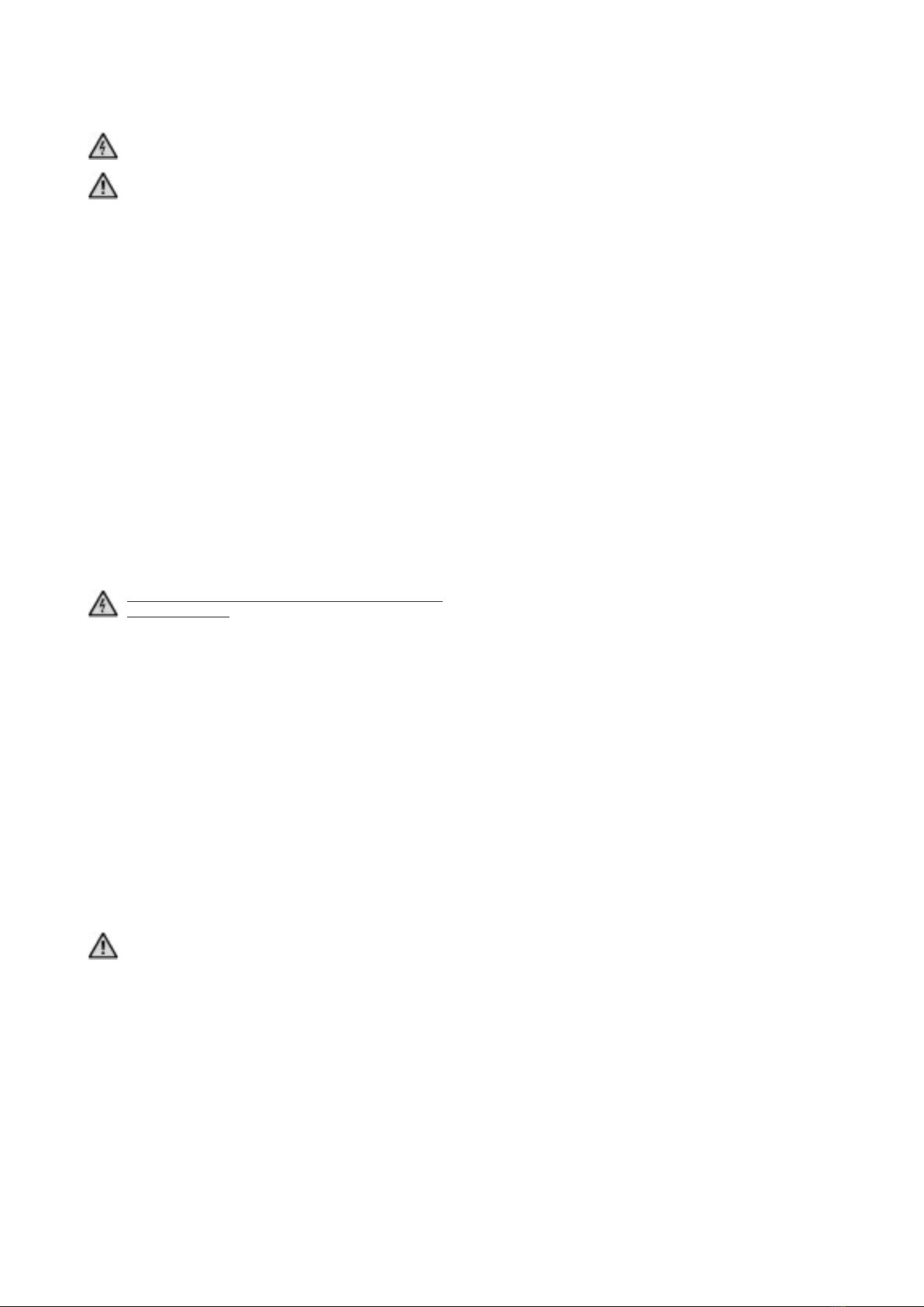
Der Spannungsbereich des Schaltnetzteils (C) umfasst 100–240 V und verfügt
über einen 3-poligen Steckeranschluss.
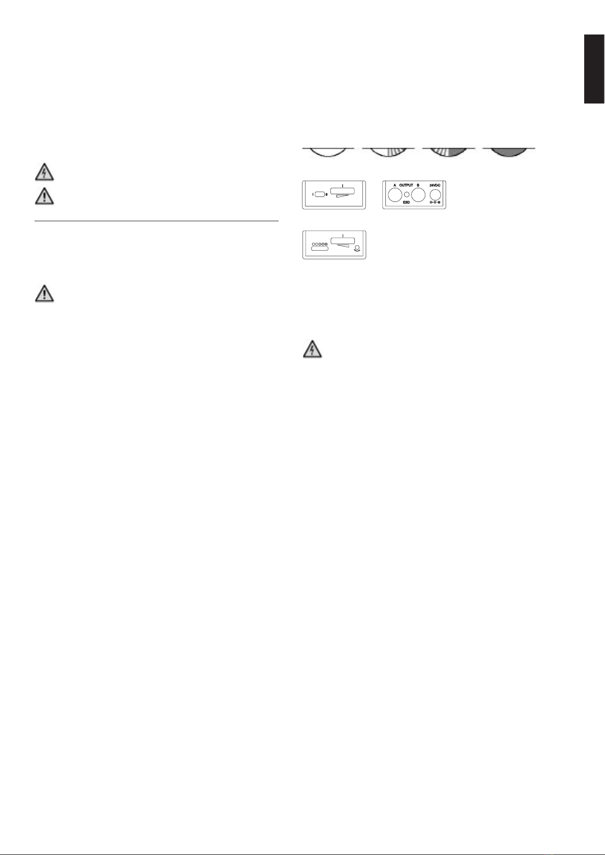
Die kompakte Steuereinheit (D) verfügt über einen Ein-/Ausschalter (1),
eine stufenlose Helligkeitsregelung (2) mit einem „Turbobereich“ sowie zwei
Anschlussbuchsen (4) zur Aufnahme der LED-Beleuchtungseinheiten. An den
Anschluss der Steuereinheit mittels Hohlsteckers (3) kann über ein geeignetes
Kabel auch eine 24V Batterie bzw. ein entsprechender Akku angeschlossen
werden.
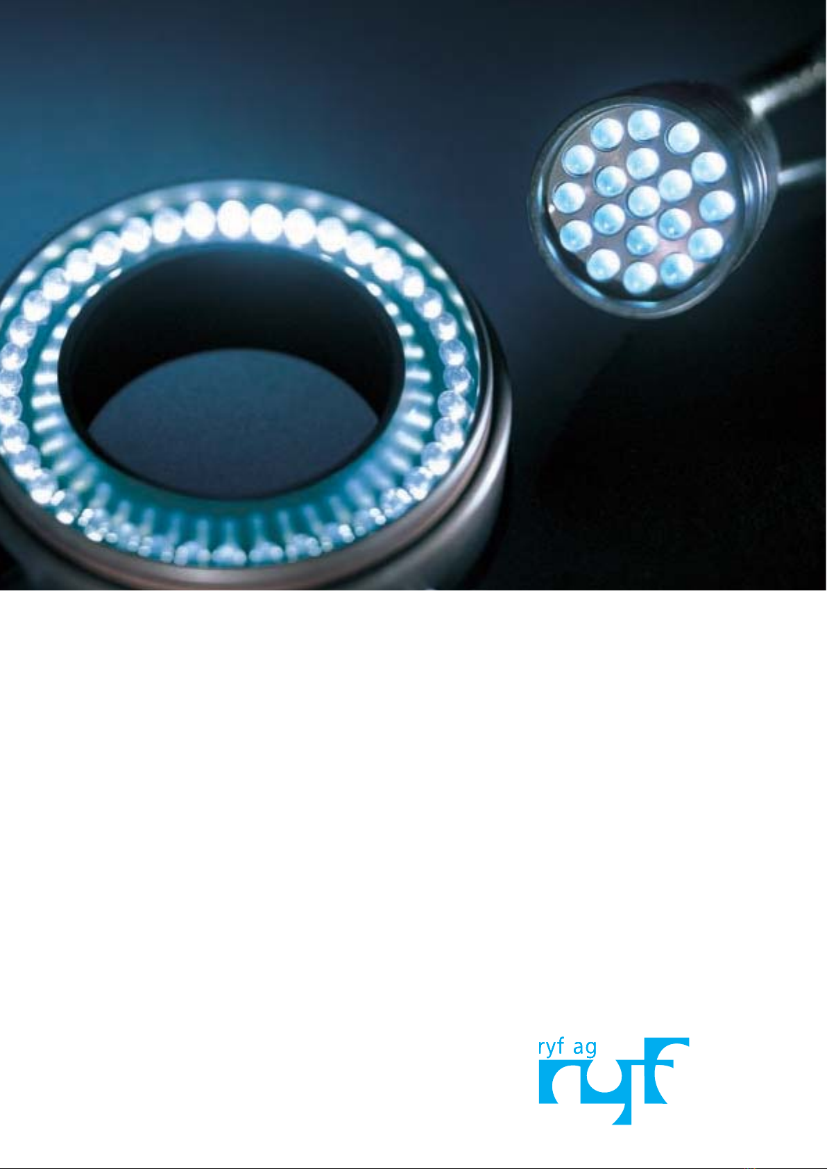
Das LED-Ringlicht (40 LEDs) (A) erlaubt eine außergewöhnlich helle und
homogene Ausleuchtung von Flächen und ist für Mikroskope mit einem Objek-
tivdurchmesser von 66 mm ausgelegt. Für andere Mikroskope stehen geeignete
Adapter zur Verfügung. Die Befestigung des Ringlichtes erfolgt objektivscho-
nend mittels Feder und Schraube (7).
Der LED-Spot (19 LEDs) (B) kann mittels Schwanenhals (6) direkt am Mikroskop
befestigt werden oder mittels Schwanenhals und Basisplatte an beliebiger
Stelle positioniert werden. Ein umfangreiches Zubehör erlaubt einen vielfältigen
Einsatz dieser LED-Beleuchtung.
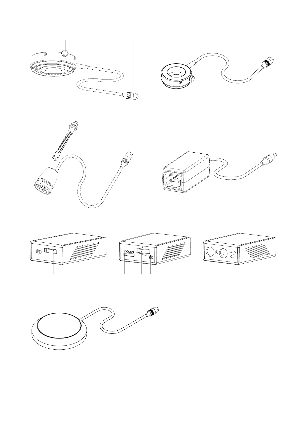
Das LED-Durchlicht (20 LEDs) (E) kann anstelle des mikroskopeigenen Objekt-
trägers zur Durchleuchtung von transparenten Objekten verwendet werden.

In dieser Betriebsanleitung werden zwei Gefahrensymbole verwendet:
Warnung vor gefährlicher elektrischer Spannung!
Warnung vor einer Gefahrenstelle. Achtung, Dokumentation beachten!
Dieses Kapitel behandelt die Sicherheitshinweise, die beim Einsatz des Gerätes
unbedingt einzuhalten sind.
BEACHTEN SIE IN IHREM EIGENEN INTERESSE ALLE SICHERHEITSHINWEISE,
die auf dem Gerät und in dieser Broschüre angeführt werden.
Zielpublikum
Personen, die mit dem Gerät arbeiten, müssen die für die Tätigkeit relevanten
Kapitel lesen. Dies gilt insbesondere für das Kapitel „Hinweise zu Ihrer Sicher-
heit“
Produktbeobachtungspflicht
Der Benutzer muss Veränderungen im Betriebsverhalten oder an sicherheits-
relevanten Geräteteilen sofort einer zuständigen Person oder dem Hersteller
melden.
Aufbewahrungsort der Betriebsanleitung
Es wird empfohlen, die Betriebsanleitung in unmittelbarer Nähe des Geräts
aufzubewahren, um sicherzustellen, dass sie im Bedarfsfall sofort vom Benutzer
eingesehen werden kann.
Gesetzliche Vorschriften
Die allgemein gültigen nationalen und lokalen Sicherheits- und Unfallverhü-
tungsvorschriften sind ebenso einzuhalten wie die ergänzenden Benutzerricht-
linien des Betreibers.
Technische Änderungen am Gerät sind in jedem Fall zu
unterlassen!
Als verbindliche Einsatzgrenzen gelten die Angaben im Kapitel „Technische
Daten“.
Betreiben Sie das Gerät nicht in der Nähe von Wasser oder in Räumen mit
extremer Luftfeuchtigkeit. HINWEIS: Zur Vermeidung von Elektroschocks setzen
Sie die Beleuchtung weder Regen noch hoher Luftfeuchtigkeit aus.
VERSCHÜTTEN SIE NIEMALS FLÜSSIGKEIT AUF DEM GERÄT, SCHIEBEN SIE
KEINE FREMDKÖRPER IN DAS PRODUKT! Sie könnten dadurch Elektroschocks
oder Geräteschäden auslösen.
In unmittelbarer Nähe des Gerätes sollen NIEMALS BRENNBARE MATERIALIEN
plaziert sein. Das Gerät ist von jeglichen Hitzequellen fernzuhalten. Das Gerät
ist nicht für den Einsatz in explosionsgefährdeten Bereichen zugelassen!
Das Gerät darf nur mit der vorgeschriebenen Netzspannung betrieben werden.
Öffnen Sie niemals das Gerät oder Komponenten, außer es wird später in dieser
Anleitung ausdrücklich darauf hingewiesen.
Blicken Sie niemals direkt in die LEDs, wenn diese eingeschaltet sind,
da Sie sonst Augenverletzungen riskieren!
Reinigung
Trennen Sie das Produkt vor der Reinigung vom Stromnetz und verwenden Sie
zur Reinigung nur ein feuchtes Tuch aber auf keinen Fall brenn- und entflamm-
bare Flüssigkeiten. Falls versehentlich Flüssigkeit ins Innere des Geräts gelangt,
Gerätestecker sofort abziehen und Gerät vor der nächsten Inbetriebnahme
trocknen lassen.
Ersatzteile
Es dürfen nur Orginalersatzteile verwendet werden. Andernfalls können
Personen- oder Sachschäden entstehen. Die Artikelnummern sind im Kapitel
„Ersatzteile“ angeführt.
Verantwortung
Der Betreiber ist als übergeordnete juristische Person verantwortlich für die
bestimmungsgerechte Verwendung des Produkts sowie für die Information
anderer Benutzer und legt die Kompetenzen für die Gerätebedienung fest.
ZIEHEN SIE DAS NETZKABEL AB, wenn das Gerät längere Zeit unbenutzt bleibt.
VERWENDEN SIE NUR ORIGINAL-NETZKABEL Verlegen Sie das Kabel so, dass
es weder eingeklemmt noch durchtrennt werden kann.
Verwenden Sie aus Sicherheitsgründen ausschließlich ein 3-poliges Netzkabel
mit Erdleiter.
In dieser Broschüre nicht beschriebene Reparaturen dürfen nur von autorisierten
Werkststätten durchgeführt werden.
Der Hersteller haftet nicht für Schäden durch Nichtbeachtung obiger Hinweise!
Stand der Technik
Die LED-Beleuchtungen von Photonic entsprechen dem letzten Stand der Tech-
nik unter Verwendung anerkannter sicherheitsrelevanter Regeln.
Dieses Gerät wurde nach folgenden Richtlinien und Standards konstruiert und
gebaut:
TEEC/89/336: Elektromagnetische Verträglichkeit (CE)
TISO 9001/2: Qualitätssysteme für Entwicklung und Produktion
HINWEISE ZUR IHRER SICHERHEIT

Die einzelnen Systemelemente aus der Verpackung nehmen und auf eine ausrei-
chend große horizontale Fläche stellen.
Die LED-Beleuchtung muss für eine optimale Funktion exakt plaziert sein.
Beachten Sie dabei folgende Kriterien:
Tkeine hohe Luftfeuchtigkeit (siehe Technische Daten)
Tkeine hohe Raumtemperatur (siehe Technische Daten)
Das Gerät darf nur mit der vorgeschriebenen Netzspannung betrieben
werden. Schließen Sie das Gerät nur an Steckdosen mit Schutzerde an!
Lüftungsschlitze freihalten!
Die Steuereinheit darf am Stromnetz nur mit dem mitgelieferten Schalt-
netzteil betrieben werden!
Stecken Sie das Netzteil einerseits mittels Hohlstecker (9) an die Steuereinheit
(3) (24 V DC-Eingang) andererseits mittels Netzkabel (8) an das Stromnetz
(100–240 V AC, 50–60 Hz). Wenn nötig, verwenden Sie den ESD Stecker (10)
zum Potentialausgleich.
Stecken Sie nun die LED-Beleuchtung in die Steuereinheit. Verwenden
Sie für das LED-Ringlicht 66/40 (und alle zukünftigen Produkte mit 40
LEDs) nur den Port A der Steuereinheit. LED-Spot, LED-Durchlicht und LED-Ring-
licht 38/20 können auf Port A und/oder B verwendet werden.
Mit den beiden Ports A und B (4) der Steuereinheit, ergeben sich folgende
Möglichkeiten:
T1 LED Ringlicht 66/40 auf Port A
T1 oder 2 LED Spots oder LED Durchlicht oder LED Ringlicht 38/20 auf Port
A und B
Das LED-Ringlicht kann nun direkt auf Mikroskop-Objektiven mit einem Durch-
messer von 66 mm mittels oberflächenschonendem Klemmring befestigt wer-
den. Für Objektive anderer Durchmesser stehen eine Vielzahl von Adapter zur
Verfügung.
Für die Montage des LED-Spots stehen „Schwanenhälse“ (6) unterschiedlicher
Länge und Gewinde zur Verfügung, wodurch die LED-Spots in jede gewünschte
Lage gebracht werden können. Diese steckt man einfach mit dem Ende an
dem sich ein O-Ring befindet in die Öffnung des LED-Spots. Das andere Ende
schraubt man entweder direkt an das Mikroskop oder in eine optionale Boden-
platte.
Mittels Schalter an der Steuereinheit (1) kann die LED Beleuchtung eingeschal-
tet werden (I...eingeschaltet, 0...ausgeschaltet).
Das Potentiometer-Rad (2) dient der Helligkeitsregelung, wobei der Strom von
3 mA bis 30 mA variiert werden kann. Beachten Sie dabei, dass die Höhe des
Stromes zwar die Helligkeit, aber auch die Lebensdauer der LEDs beeinflusst.
Arbeiten Sie daher immer nur mit der Helligkeit, die Sie auch wirklich benöti-
gen.
An einer Skala kann man die aktuelle Potentiometer-Rad Einstellung ungefähr
ablesen.
Minimum (3 mA) 10 mA 20 mA Maximum (30 mA)
Ansicht der Standard-Steuereinheit
Ansicht der Steuereinheit mit Segmentsteuerung
Mit dem Ein/Aus-Schalter kann man auch folgende Segmente anwählen:
THalbkreis
TViertelkreis
T2 Viertelkreise gegenüber
Diese Segmentauswahl kann man mittels (13) rotieren lassen.
Öffnen Sie niemals das Gerät oder die Komponenten.
Lebensdauer
LED-Chips besitzen eine typische Lebensdauer von über 100.000 Stunden. Die
tatsächliche Lebensdauer hängt allerdings erheblich von der Umgebungstem-
peratur und vom Betriebsstrom der LEDs ab. Ein höherer Betriebsstrom erzeugt
zwar mehr Licht, aber auch mehr Wärme, was wiederum zu einer Verkürzung
der Lebensdauer der LEDs führt.
Grundsätzlich nimmt bei LEDs auch die Helligkeit über die Lebensdauer ab. Bei
der höchstmöglichen Helligkeit – in der „Turbostellung“ des Potentiometerrades
– fällt diese nach ca. 7.000 Stunden auf die Hälfte ab, hingegen wird derselbe
Wert bei der 10 mA-Stellung erst nach über ca. 20.000 Stunden erreicht. Unter-
halb der 10 mA-Stellung wird dieser Wert noch weiter erheblich erhöht.
Um die Lebensdauer der LEDs zu erhöhen, sollte daher immer nur die tatsäch-
lich benötigte Helligkeit eingestellt werden.
Defekte LEDs können getauscht werden. Setzen Sie sich diesbezüglich mit dem
Händler oder dem Hersteller in Verbindung.
Deutsch
AUFSTELLEN UND ANSCHLIESSEN BEDIENUNG UND BETRIEB

Artikelbeschreibung Artikelnummer
Desktop-Schaltnetzteil 100–240 V AC, 24 V DC, 15 W 302 11 002
Standard-Steuereinheit (max. 40 LEDs) 302 11 001
Segment-Steuereinheit (max. 40 LEDs) 302 11 004
Segment-Steuereinheit (max. 80 LEDs) nur für LED-Ringlicht 66/80 302 11 005
LED-Ringlicht 66/40 (40 LEDs) 302 10 004
LED-Ringlicht 66/80 (80 LEDs) 302 30 002
LED-Ringlicht 38/20 (20 LEDs) 302 30 001
LED-Spot (19 LEDs) 302 20 001
LED Durchlicht (20 LEDs) 302 40 001
Schwanenhals für Spot M5 – 85 mm 302 21 005
Schwanenhals für Spot M5 – 200 mm 302 21 006
Schwanenhals für Spot M5 – 300 mm 302 21 007
Farbfilter blau für LED-Spot 302 21 001
Farbfilter grün für LED-Spot 302 21 002
Farbfilter gelb für LED-Spot 302 21 003
Farbfilter rot für LED-Spot 302 21 004
Basisplatte mit M5 Adapter für Schwanenhals 302 21 008
Polarisationsfilter SET für LED Ringlicht 66/40 302 31 001
Klemmring für LED-Ringlicht 66/40 & 66/80 301 22 102
Schraube für Klemmring 302 31 002
Adapter für:
Objektiv 66/58mm 595-32-258
Olympus SZ III, SZ 60, SZ 1145 598-30-002
Olympus SD, SF, SZ mit Vorsatzlinse 598-30-017
Olympus SZH, SZX9, SZX12, Nikon SMZ 800, SMZ /U, 10A, 1000, 1500 598-32-043
Nikon (außer SMZ-1) 598-30-004
Olympus SD, SF, SZ ohne Vorsatzlinse, Nikon SMZ-1, 1B, 2B, 2T 598-32-049
Nikon SMZ 645 and SMZ 660 598-32-050
Universal Adapter für Durchmesser 38 mm bis 58 mm 598-30-022
Adapter DM38 / DM36 mm
Netzkabel 3polig IEC320 für:
EU 301 17 104
CH 301 17 105
IT 301 17 103
UK 301 17 106
USA/CAN/J 301 17 102
AUS 301 17 107
ERSATZTEILE UND ZUBEHÖR
Artikelnummer
ENSS-15.001
619-30-001
619-30-021
619-30-022
619-20-002
619-20-035
619-20-006
619-20-011
619-20-032
619-30-003
619-30-004
619-30-005
619-30-010
619-30-011
619-30-012
619-30-013
619-30-007
619-20-021
595-32-013
619-30-008
595-32-258
598-30-002
598-30-017
598-32-043
598-30-004
598-32-049
598-32-050
598-30-022
619-32-056
ELN-3.001
ELN-3.002
ELN-3.009
ELN-3.004
ELN-3.003
ELN-3.006

Die Entwicklung dieses Produktes ist einer laufenden Weiterentwicklung
unterworfen. Obwohl wir uns bemühen, diese Bedienungsanleitung auf dem
aktuellsten Stand zu halten, behalten wir uns vor, Gerätedaten jederzeit ohne
vorherige Ankündigung zu ändern. Die Erstellung der Bedienungsanleitung
erfolgt vorbehaltlich Irrtümern und Druckfehlern.
Deutsch

(A) 5 Connecteur de 4
7 Vis de fixation
(B) 5 Connecteur de 4
6 Col de cygne
(C) 8 Connecteur du câble de réseau
9 Connecteur pour 3
(D) 1 Interrupteur de marche/arrêt
2 Réglage de la luminosité
3 Alimentation 24 V
4 A/B Port A/B pour spot/lampe annulaire
10 Connecteur ESD
12 Commutateur de segments
13 Rotation des segments
(E) Éclairage diascopique
(A)
757 5
(B) (C)
658 9
1 2 12 2 13 4A 10 4B 3
(D)
(E)

Français
MODE D’EMPLOI DE L’ÉCLAIRAGE PAR LED
DÉSCRIPTION
Cet éclairage par LED (diodes électroluminescentes) d’un nouveau type a été
développé pour l’éclairage en stéréomicroscopie dans l’industrie et les labora-
toires.
Utiliser les illustrations imprimées sur la deuxième de couverture de ce mode
d’emploi. Ce produit fournit un éclairage par LED de grande valeur qui s’utilise
partout où l’on a besoin d’un éclairage puissant mais qui ne génère pas de
chaleur. Les LED servent à éclairer.
Caractéristiques de ce type d’illumination :
TTempérature de couleur 5 000 K (lumière du jour !)
TAbsence d’ondulation et de clignotement
TLongue durée de vie des LED
TFonctionnement silencieux sans vibration
TModèle extrêmement compact
TFonctionnement sur batterie possible
La conception modulaire de l’éclairage par LED procure, en association avec
Tla lampe annulaire – un éclairage homogène et sans ombre portée ;
Tle spot – un éclairage dirigé ;
Tla diascopie – un éclairage diascopique homogène.
Système d’éclairage :
TAlimentation électrique en mode commutateur (bureau) ;
Tunité de commande et
TUnité de LED (1 lampe annulaire 66/40 ou 1 ou 2 spots ou lampes à
transmission ou lampes annulaires 38/20)
La plage de tension de l’alimentation électrique en mode commutation (C)
est comprise entre 100 et 240 V avec un raccord enfichable à 3 broches.
L’unité de commande (D) compacte dispose d’un interrupteur de marche-arrêt
(1), d’un réglage continu de la luminosité (2) ayant une »plage turbo« ainsi que
de deux connecteurs (4) pour les unités d’éclairage par LED. En utilisant un
câble approprié, il est possible de connecter à l’unité de commande au moyen
du connecteur creux (3) une pile de 24 V ou l’accumulateur correspondant.
La lampe annulaire à LED (40 LED) (A) permet d’obtenir un éclairage
exceptionnellement clair et homogène des surfaces ; elle est prévue pour
les microscopes équipés d’un objectif de 66 mm de diamètre. Pour les autres
microscopes, des adaptateurs appropriés sont disponibles. La fixation de la
lampe annulaire s’effectue au moyen d’un ressort et d’une vis (7), de façon à
préserver l’objectif.
Le spot à LED (19 LED) (B) peut être fixé directement au microscope au moyen
d’un col de cygne (6) ou bien placé à l’endroit souhaité au moyen du col de
cygne et de l’embase. Un jeu complet d’accessoires permet d’utiliser cet
éclairage par LED de diverses façons.
L’éclairage diascopique par LED (20 LED) (E) peut être utilisé à la place du
porte-objet spécifique au microscope pour éclairer les objets transparents.
Veuillez lire l’intégralité de ce mode d’emploi avant de mettre en service l’éclairage par LED !
Caractéristiques techniques
Lampe annulaire à LED 66/40 Lampe annulaire à LED 66/80 Lampe annulaire à LED 38/20
Diodes 40 LED blanches 80 LED blanches 20 LED blanches
Température de couleur 5 000 K 5 000 K 5 000 K
Dimensions extérieures : Ø94x25 extérieures : Ø 112 x 23,5 mm extérieures : Ø60x25mm
intérieures : Ø66mm intérieures : Ø66mm intérieures : Ø38mm
Fixation circulaire avec ressort et vis
Spot à LED Éclairage diascopique par LED
Diodes 19 LED blanches 20 LED blanches
Température de couleur 5 000 K 5 000 K
Dimension Ø34mmx45mm
Fixation par col de cygne
Plaque de support en PVC noir, Ø 120 x 24,5 mm
Porte-objet en verre composite, Ø95mm
Surface éclairée Ø55mm
Unité de commande Standard avec des segments (40 LED) avec des segments (80 LED)
Alimentation électrique 24VCC+/–5%,douille cannelée 5,5 x 2,1 mm
250 mA 250 mA 500 mA
Dimension 95,5 x 64 x 29 mm 95,5 x 64 x 29 mm 102 x 106 x 39 mm
Connecteurs de la lampe annulaire/du spot 2 prises mini-Din à 9 broches 2 prises mini-Din à 9 broches D-Sub (25 broches)
Commutateur marche/arrêt marche/arrêt avec commande des segments avec commande des segments
Bouton pour rotation des segments – 1 2
Molette de potentiomètre 3–30 mA, avec graduations
Connecteur ESD connecteur banane de 4 mm
Température ambiante 10 à40 °C (*)
Humidité relative 30 à70 %
Symbole test CE
Bloc d’alimentation
Raccord enfichable à 3 broches CEI 320
Plage de tension 100–240 V
Fréquence de réseau 50–60 Hz
Puissance absorbée max. 15 VA
Classe de protection I
Symbole test CE, UL, CSA
(*) Les LED peuvent fonctionner même si la température ambiante atteint 40 °C mais leur durée de vie est d’autant plus faible que la température et l’humidité sont élevées. Pour un fonctionnement optimal,
une température ambiante de 25 °C (ou moins) et une hygrométrie relative de 50 % (ou moins) sont appropriées.
Marque de conformité CE : confirme que l’unité de commande est conforme à la directive 89/336/CEE concernant la compatibilité électromagnétique.

Ce mode d’emploi contient deux symboles de danger :
Attention : risque de choc électrique !
Attention : zone dangereuse. Avertissement : se reporter à la documen-
tation d’accompagnement !
Ce chapitre contient des consignes de sécurité à respecter scrupuleusement
lors de l’utilisation du dispositif.
IL Y VA DE VOTRE INTÉRÊT DE FAIRE ATTENTION À TOUS LES AVERTISSE-
MENTS inclus dans ce chapitre et ce manuel.
Audience-cible
Les personnes travaillant avec le dispositif doivent impérativement lire les cha-
pitres relatifs à leur activité. Ceci s’applique tout particulièrement au chapitre
intitulé « Informations sur la sécurité ».
Obligation d’observation du produit
L’opérateur doit signaler immédiatement au superviseur responsable ou au
fabricant toute irrégularité ou modification des composants mettant en jeu la
sécurité du dispositif.
Conservation du mode d’emploi
Il est recommandé de conserver le mode d’emploi à proximité de
l’appareil et le rendre ainsi rapidement accessible au personnel d’exploitation.
Dispositions légales
Il y a lieu d’observer strictement les règlements nationaux et régionaux de
sécurité et pour la protection contre les accidents en vigueur, en plus des
recommandations émanant de l’unité opérationnelle.
Aucune modification technique ne peut être apportée au
dispositif en aucune circonstance !
Se reporter aux spécifications mentionnées dans le chapitre « Caractéristiques
techniques » pour déterminer les limites d’exploitation.
NE PAS UTILISER cette unité à proximité d’eau ou dans un endroit à forte humi-
dité. AVERTISSEMENT : pour la prévention de choc électrique, ne pas exposer
ce matériel à l’eau de pluie ou à l’humidité élevée.
NE JAMAIS VERSER DE LIQUIDE NI INSÉRER D’OBJETS DANS L’UNITÉ ! Cela
pourrait être la cause de choc électrique ou endommager l’unité.
NE JAMAIS PLACER DE MATIÈRES INFLAMMABLES sur ou à proximité de
l’unité. Conserver l’unité à l’écart de toute source de chaleur. Le dispositif
n’a pas été homologué pour fonctionner dans des zones sujettes aux dangers
d’explosion !
Le dispositif fonctionne uniquement avec la tension de secteur indiquée.
Ne jamais ouvrir le dispositif ou aucun de ses composants à moins d’instruction
expresse dans le présent document.
Ne jamais regarder directement les LED quand elles sont allumées, en
raison des risques de blessures oculaires !
Nettoyage
débrancher le produit du secteur avant de le nettoyer. N’utiliser qu’un chiffon
humide ; n’utiliser en aucun cas des matières combustibles et inflammables.
Si par mégarde des liquides pénètrent dans le dispositif, débrancher immé-
diatement le câble de réseau et laisser sécher l’unité complètement avant sa
réutilisation.
Pièces de rechange
utiliser exclusivement des pièces de rechange d’origine. Dans le cas contraire,
il peut en résulter des accidents corporels et des dommages matériels. On
trouvera les codes des composants au chapitre « Pièces de rechange ».
Responsabilité
en tant qu’entité juridique finale, l’institution opérationnelle est responsable
de la bonne utilisation du dispositif et de la remise d’informations nécessaires
aux autres opérateurs et spécifie les compétences requises au fonctionnement
du dispositif.
DÉBRANCHER LE CÂBLE DE RÉSEAU lorsque l’unité est inutilisée pendant une
longue période. UTILISER UNIQUEMENT LE CÂBLE DE RÉSEAU D’ORIGINE.
Acheminer le câble de façon à ce qu’il n’y ait ni pincement ni coupure.
Pour des raisons de sécurité utiliser uniquement un câble de réseau à 3 pôles
avec conducteur de mise à la terre.
Les réparations non décrites dans ce document ne doivent être effectuées que
par des ateliers agréés !
Le fabricant ne peut être tenu responsable de dommages résultant du non-
respect des présentes instructions !
État de la technique
les éclairages par LED de Photonic correspondent à l’état le plus récent de la
technique et sont conformes aux règles de sécurité reconnues.
Cet instrument a été conçu et construit conformément aux réglementations et
normes suivantes :
TEEC/89/336 : compatibilité électromagnétique (CE)
TISO 9001/2 : systèmes de qualité pour le développement et la
production
INFORMATIONS SUR LA SÉCURITÉ

Die einzelnen Systemelemente aus der Verpackung nehmen und auf eine ausrei-
Retirer les composants individuels du système de leur emballage et les placer
sur une surface suffisamment grande.
Pour un fonctionnement optimal, l’éclairage par LED doit placé de façon précise.
Observer les critères suivants :
Tl’hygrométrie ne doit pas être élevée (voir les données techniques)
Tla température de l’air ne doit pas être élevée (voir les données
techniques)
Le dispositif fonctionne uniquement avec la tension de secteur nomi-
nale. Raccorder l’unité uniquement à des douilles mises à la masse.
Ne pas obstruer les grilles d’aération !
L’unité de commande doit être branchée au secteur au moyen du bloc
d’alimentation secteur fourni !
Raccorder le bloc d’alimentation à l’unité de commande (3) (24 V CC en entrée)
au moyen du connecteur creux (9) d’une part et au secteur (100 à 240 V CA,
50 à 60 Hz) au moyen du câble d’alimentation électrique (8) d’autre part. Au
besoin, utilisez le connecteur ESD (10) pour l’équilibrage du potentiel.
Branchez ensuite l’éclairage à DEL dans l’unité de commande. Pour la
lampe annulaire LED 66/40 (et tous les produits futurs à 40 LED), utili-
sez toujours le port A de l’unité de commande. Le spot, la lampe à transmission
et la lampe annulaire de 38/20 peuvent être branchés indifféremment sur le
port A ou B.
Les deux ports A et B (4) de l’unité de commande permettent les configurations
suivantes :
T1 lampe annulaire LED 66/40 sur le port A
T1 ou 2 spots LED ou lampes à transmission LED ou lampes annulaires LED
38/20 sur les ports A et B
La lampe annulaire à LED ne peut être fixée directement que sur les objectifs de
microscope ayant un diamètre de 66 mm, au moyen d’une bague de serrage qui
en préservera la surface. Pour les objectifs de diamètres différents, un grand
nombre d’adaptateurs sont disponibles.
Pour le montage des spots à LED, des cols de cygne (6) de longueurs et fileta-
ges différents sont disponibles, ce qui permet de placer les spots à LED dans
la position souhaitée. Il suffit d’introduire l’extrémité du col qui est équipée du
joint torique dans l’orifice du spot à LED. L’autre extrémité se visse directement
sur le microscope ou sur un socle optionnel.
Le commutateur situé sur l’unité de commande (1) permet de mettre sous
tension l’éclairage à LED (I... marche, 0... arrêt).
La molette du potentiomètre (2) sert à régler la luminosité, l’intensité du
courant pouvant varier de3à30mA.Tenir compte du fait que l’intensité a un
effet sur la luminosité mais aussi sur la durée de vie des LED. N’utiliser que le
réglage de luminosité indispensable.
Une graduation sur la molette du potentiomètre permet de lire le réglage
actuel.
Minimum (3 mA) 10 mA 20 mA Maximum (30 mA)
Vue de l’unité de commande standard
Vue de l’unité de commande avec commande des segments
L’interrupteur permet aussi de sélectionner les segments suivants :
Tdemi-cercle
Tquart de cercle
Tdeux quarts de cercle opposés
Vous pouvez faire tourner cette segments à l’aide de (13)
Ne pas ouvrir l’unité ou ses composants individuels !
Durée de vie
Les puces des LED ont une durée de vie typique supérieure à 100 000 heures.
La durée de vie effective dépend toutefois de la température ambiante et du
courant de service des LED. Un courant de service élevé produit plus de lumière,
mais aussi plus de chaleur, ce qui entraîne à son tour une réduction de la durée
de vie des LED.
Une caractéristique fondamentale des LED est que leur luminosité diminue avec
le temps. La plus grande luminosité possible – correspondant à la „position
turbo“ de la molette du potentiomètre – est réduite de moitié au bout de
7 000 heures environ, alors qu’en position 10 mA, il faut plus de 20 000 heures
d’utilisation pour arriver à ce résultat. Avec une position inférieure à 10 mA,
la valeur résultante est encore plus grande.
Pour augmenter la durée de vie des LED, il ne faut utiliser que le réglage de la
luminosité vraiment nécessaire.
Le remplacement des LED défectueuses est possible. Contacter le revendeur ou
le fabricant à cet effet.
INSTALLATION ET BRANCHEMENT FONCTIONNEMENT
Français

Description du composant Numéro article
Bloc d’alimentation secteur 100–240 V AC, 24 V DC/15 W 302 11 002
Unité de commande (max. 40 LED) 302 11 001
Unité de commande avec commande des segments (max. 40 LED) 302 11 004
Unité de commande avec commande des segments (max. 80 LED) pour lampe annulaire à LED 66/80 302 11 005
Lampe annulaire à LED 66/40 (40 LED) 302 10 004
Lampe annulaire à LED 66/80 (80 LED) 302 30 002
Lampe annulaire à LED 38/20 (20 LED) 302 30 001
Spot à LED (19 LED) 302 20 001
Éclairage diascopique à LED (20 LED) 302 40 001
Col de cygne pour spot M5 – 85 mm 302 21 005
Col de cygne pour spot M5 – 200 mm 302 21 006
Col de cygne pour spot M5 – 300 mm 302 21 007
Filtre bleu pour spot 302 21 001
Filtre vert pour spot 302 21 002
Filtre jaune pour spot 302 21 003
Filtre rouge pour spot 302 21 004
Embase avec adaptateur M5 pour col de cygne 302 21 008
Filtre à polarisation réglé pour l’éclairage diascopique à LED 66/40 302 31 001
Bague de serrage pour la lampe annulaire à LED 66/40 + 66/80 301 22 102
Vis de la bague de serrage pour lampe annulaire 302 31 002
Adaptateur de lampe annulaire à LED pour :
Objectif 66/58 mm 595-32-258
Olympus SZ III, SZ 60, SZ 1145 598-30-002
Olympus SD, SF, SZ avec bonnette 598-30-017
Olympus SZH, SZX9, SZX12, Nikon SMZ 800, SMZ /U, 10A, 1000, 1500 598-32-043
Nikon (excepté SMZ-1) 598-30-004
Olympus SD, SF, SZ sans bonnette, Nikon SMZ-1, 1B, 2B, 2T 598-32-049
Nikon SMZ 645 et SMZ 660 598-32-050
Adaptateur universel pour diamètres de 38 à 58 mm 598-30-022
Adaptateur DM38 / DM36 mm
Câble de réseau à 3 broches CEI320 pour :
UE 301 17 104
CH 301 17 105
IT 301 17 103
RU 301 17 106
E.-U./CAN/J 301 17 102
AUS 301 17 107
PIÈCES DE RECHANGE ET ACCESSOIRES
Numéro article
ENSS-15.001
619-30-001
619-30-021
619-30-022
619-20-002
619-20-035
619-20-006
619-20-011
619-20-032
619-30-003
619-30-004
619-30-005
619-30-010
619-30-011
619-30-012
619-30-013
619-30-007
619-20-021
595-32-013
619-30-008
595-32-258
598-30-002
598-30-017
598-32-043
598-30-004
598-32-049
598-32-050
598-30-022
619-32-056
ELN-3.001
ELN-3.002
ELN-3.009
ELN-3.004
ELN-3.003
ELN-3.006

Le produit considéré fait l’objet de développements et de perfectionnements
permanents. Bien que nous nous efforcions de mettre à jour ce manuel
d’utilisation régulièrement, nous nous réservons le droit de modifier les
caractéristiques techniques sans préavis. Ce manuel est réalisé sous réserve
de toute faute ou omission et de toute erreur typographique.
Français

(A) 5 Spina per 4
7 Vite di bloccaggio
(B) 5 Spina per 4
6 Supporto flessibile
(C) 8 Spina per cavo di rete
9 Spina per 3
(D) 1 Interruttore di accensione-spegnimento
2 Regolazione luminosità
3 Alimentazione a 24 V
4 A/B Porta A/B per spot/luce ad anello
10 Connettore ESD
12 Interruttore segmenti
13 Rotazione segmento
(E) Luce trasmessa
(A)
757 5
(B) (C)
658 9
1 2 12 2 13 4A 10 4B 3
(D)
(E)
This manual suits for next models
2
Table of contents
Languages: