RYKOV SNOWBLADE 120 User manual

RYKOV Libčany, s.r.o.
Libčany 14
50322 Libčany
Czech Republic
T/F +420 495 585 422
rykov@rykov.cz
www.rykov.cz
USER GUIDE – INSTALLATION
AND OPERATION
INSTRUCTIONS
SNOWBLADE 120-150
(
ATV, UTV MODEL)
EAN: SB-120-02-02 08/2022

2
Contents
1 Introduction.................................................................................................................. 3
1.1 Basic warnings……........................................................................................ 3
2 Safety of operation...................................................................................................... 4
2.1 Safety regulations.......................................................................................... 4
2.2 Safety pictograms.......................................................................................... 4
3 Basic information........................................................................................................ 5
3.1 Snowblade use.............................................................................................. 5
3.1.1 Technical data............................................................................... 5
3.2 Snowblade and parts description.................................................................. 5
4 Instruction of use........................................................................................................ 6
4.1 Snowblade assembly..................................................................................... 6
4.2 Total vehicle payload (ATV/ UTV) ................................................................. 7
4.3 Connecting the snowblade to the ATV/ UTV................................................. 7
4.4 Putting the snowblade into operation............................................................ 7
4.4.1 Use in slope/hill............................................................................. 8
4.5 Work with snowblade.................................................................................... 8
4.5.1 Height adjustment......................................................................... 8
4.5.2 Angle adjustment …………........................................................... 8
4.5.3 Work height adjustment................................................................. 9
4.5.4 Snow plowing method................................................................... 9
4.5.4.1 Snow plowing problems................................................. 9
5 Maintenance, care, storage........................................................................................ 10
5.1 Snowblade lubrication..................................................................................... 10
5.2 Lubrication points........................................................................................... 10
5.3 Service intervals............................................................................................ 11
5.4 Troubleshooting and solutions....................................................................... 11
5.5 Storage.......................................................................................................... 11
5.5.1 Washing and cleaning................................................................... 11
5.6 Packing material and snowblade disposal after end of lifetime.................... 12
5.7 Production tag................................................................................................ 12
6 List of spare parts........................................................................................................ 13

3
1 Introduction
Dear valued customer and user!
Thank you for your trust and purchase of our product.
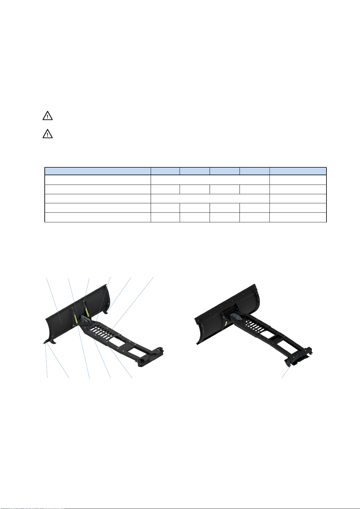
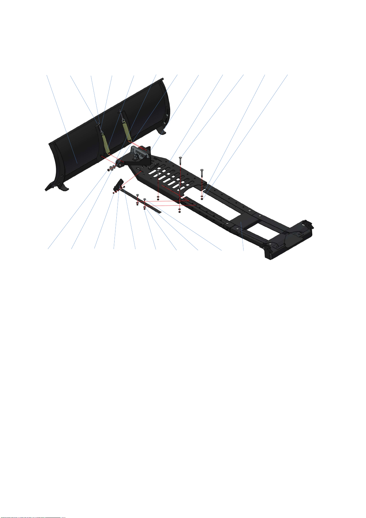
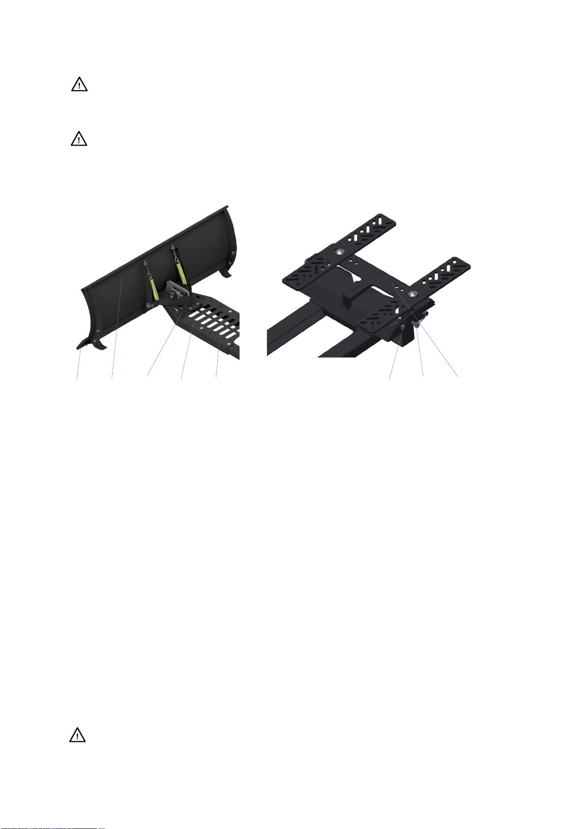
The snowblade is designated for use with ATV/UTV. Primary use is plowing of snow and impurities from
roads, sidewalks, and other applicable areas.
Please carefully read user installation and operation information.
1.1 Basic information
We strongly recommend reading and follow installation and operation instructions for safety of user,
other persons, and property.
The safety instructions given in this manual do not describe all possibilities, conditions and situations
that may occur in practice. Safety factors such as common sense, caution and diligence are not part of
this manual, but are assumed to be used by every person who handles or performs work with this
snowblade.
Only mentally and physically healthy persons may work with this snowblade. In the case of professional
use of this machine, the owner of the snowblade is obliged to ensure that the operators who will use the
machine receive training on work safety and conduct an instruction on how to operate this snowblade
and keep records of these trainings. They must also carry out the so-called categorization of works
according to the relevant national legislation.
If you do not understand some of the information in the manual, contact your supplier or the snowblade
manufacturer directly.
The instructions for use are an integral part of the snowblade. They must be always available, stored in
an accessible place where there is no risk of their destruction. When selling the snowblade to another
person, the user manuals must be handed over to the new owner.
The manufacturer is not responsible for risks, dangers, accidents, and injuries arising from the operation
of the snowblade if the above conditions are not met. The manufacturer is not responsible for damage
caused by unauthorized use, improper operation of the snowblade and for damage caused by any
modification of the snowblade without the manufacturer's consent.
When working, it is especially necessary to follow the safety regulations to avoid the risk of injury to
yourself, other people or causing damage to property.
Any unauthorized modification of the snowblade will void the warranty.
If you see this symbol in the manual, read the following information carefully!
This international safety symbol indicates important safety-related information. When
you see this symbol, be alert to the possibility of injury to yourself or others and read
the following information carefully.
Tab. 1: Symbols
The manufacturer reserves the right to technical changes and innovations that do not affect the
function and safety of the snowblade.
These changes may not be reflected in this user guide. Typographical errors reserved.

4
2 Safety of use
The machine is designed to protect the operator from flying parts as much as possible. Do not remove
any passive or active safety feature. This puts you at risk of injury.
2.1 Safety regulations
The operator of the snowblade must be over 18 years old. It is necessary to understand the
instructions for using the machine and to be aware of the general principles of occupational
safety.
Every time you use the snowblade, check that any part is not damaged or loose. Detected defects
must be removed immediately. A damaged snowblade must not be put into operation. Use only
original spare parts for repairs.
Before using the snowblade, the working area must be free of large solid objects (such as stones,
wires, loose construction debris, etc.) that could be hit or could damage the machine. If they
cannot be removed, avoid these places.
When working with the snowblade, all other people (especially children) and animals must be
outside the working area of the machine. The operator can continue working only after they
have been sent to a safe distance.
It is forbidden to remove all protective devices and covers from the snowblade.
All repairs, adjustments, lubrication, and cleaning of the snowblade must be performed when the
machine is stationary and in its secured position.
Connect and disconnect the snowblade from the ATV/UTV on a flat, dry and firm surface.
2.2 Safety pictograms
Respect the pictograms located on the machine and their meaning!
PIC. 1: Read the user manual before using the machine.
PIC. 2: Danger of being hit by flying fragments, cuttings, thrown objects, etc. Other people and
animals - keep a safe distance from the machine.
PIC. 3: Maximum speed allowed when plowing.

5
3 Basic Information
3.1 Snowblade use
The snowblade SB 120 – 150 is designed and manufactured according to the latest knowledge in the
field ATV/UTV. It stands out for its easy handling and trouble-free maintenance.
The snowblade is mainly intended for plowing snow, but also other loose materials, e.g.: garden soil,
sand, gravel, etc. The height and angle of the snowblade can be adjusted (5 positions) using a main
lever.
Use snowblade only for specified purpose. Use for any other unspecified purpose is
prohibited!
It is forbidden to remove all protective devices and covers from the snowblade.
3.1.1 Technical data
TYPE
SB 120
SB 130
SB 140
SB 150
Unit
Length (incl. main lever) 1430 - 1730 mm
Width 1200 1300 1400 1500 mm
Height (incl. main lever) 448 mm
Snowblade working width 1200 1300 1400 1500 mm
Weight 50,2 51,4 52,6 53,8 kg
Tab. 2: SB 120 Snowblade technical data
3.2 Snowblade and parts description
4.1 4.2 5.2 4.9 4.7 4.3
4.6 4.5 4.4 4.10 4.8 5.1
PIC. 4: Snowblade description view A PIC.5: Machine description view B
The main part of the snowblade is the front blade (4.1). Blade is connected via an angle adjustment
bracket (4.2) to main frame (4.3). Springs (4.4) return the front blade to the working position in the event
of an impact with a fixed obstacle. A rubber wear strip is mounted to the front part (4.5). Steel bar
reinforcement (4.6). Adjustment of the working height is possible using the skid shoes (4.7). Main control
lever (4.8) for lifting and angle setting. The snowblade is connected to the ATV/UTV by pin (5.1). (4.9)
lifting eye is dedicated for snowblade lifting and travel possition. A spring (5.2) pulls the control lever
into the secured turning position. The lever, rod and spring system (4.10) serves to unlock the
mechanism.

6
4 Instruction of use
4.1 Snowblade assembly
6.2 6.10 6.9 6.8 6.7 6.4 6.3 6.1 6.12 6.13 6.14 6.15
6.6 6.5 6.19 6.17 6.18 6.22 6.21 6.16 6.20 6.11
PIC. 6: Snowblade assembly
Assembly procedure:
1. Unpack the components from the box.
2. Put angle adjustment frame (6.1) between blade front reinforcements (6.2). Put COACH BOLT-
M10x30 into the square hole in the turning frame (6.3). Use OVERSIZED WASHER 10,5 (6.4) for
definition, attach OVERSIZED WASHER 11 (6.5) and tighten LOCKNUT M10 (6.6). Thread into the
bottom oval hole EXTENSION SPRING 5x30x120x23 (6.7). Second end of EXTENSION SPRING
attach to FORGED EYEBOLT M10x73 (6.8). FORGED EYEBOLT put into top reinforcement hole.
Put on the WASHER 10.5 (6.9) and tighten the M10 NUT (6.10) so that the threaded part of the
forged eye is approx. 15 mm from the upper return bend. Repeat the entire procedure on the other
side.
3. Connection part of main frame (6.11) slide in supporting part of main frame (6.12). The total length of
main frame set and adjust in safe position against front part of ATV/UT. After connecting the blade
to the adapter that is mounted on the ATV or UTV, the condition of collision-free rotation of the blade
must be met. This means that when the blade is turned at maximum angle position, it must not come
into contact with, for example, the front wheels etc. Assemble and connect the frames using four
COACH BOLTS-M8x65 (6.13), WASHERS 8.4 (6.14) and LOCK NUTS M8 (6.15).
4. Insert the pull control bar (6.16) into the main support frame. Insert the control lever (6.17) into the
opening and secure it with the M6x10 SCREW (6.18) and the M6 LOCK NUT (6.19). Connect the
pull control bar using two COACH BOLTS M6x16 (6.20), OVERSIZE WASHERS 6.4 (6.21) and
LOCK NUTS M6 (6.22). After tightening the screw connections, the pull control bar must be
connected and overlapping one on top of the other.

7
4.2 Total ATV/UTV payload
The ATV/UTV payload cannot be exceeded after snowblade connection.
Considering the operating weight of the ATV/UTV + the weight of the blade + the weight of the
operator is strongly advised.
The stability of the ATV/UTV changes when the snowblade is attached.
4.3 Attaching the snowblade to the ATV/UTV
7.2 7.3 7.4 7.5 7.1 8.1 8.2 8.3
PIC. 7: Front part of main frame PIC. 8: Rear part of main frame
Snowblade connection to ATV/UTV:
1. Slide the snowblade under ATV/UTV the way that adapter snap on jaws (8.1) will be located under
adapter pins (8.2). Now put the hook in one of the cross holes (7.1), you will use this hole every time
you will connect the snowblade to ATV/AUT.
2. Lift the snowblade using the winch the bottom edge of snowblade (7.2) must be approx. 20cm above
the ground. Grab the snowblade from front (7.3) and using the swing move push and clip the
snowblade frame in adapter (8.3). Control lever (7.4) should be in back position. If all done correct
the side-by-side movement of snowblade should be less than 10cm. Lower the snowblade to the
ground and reconnect the winch hook in hook lifting eye (7.5)!
3. Disconnection of the blade from the machine when lowered to the ground. Pull the control lever (7.4)
towards font. Push the snowblade beck from machine. Release the winch hook from snowblade
lifting eye (7.5). Now the snowblade is disconnected.
4.4 Putting the snowblade into operation
1. Connect the snowblade to the ATV or UTV.
2. Using the winch lift the snowblade in proper position against ground.
Check that all persons, animals, children are at a safe distance from the device! If not, do
not proceed with this activity!

8
4.4.1 Use in slope/hill
Do not perform the work with snowblade in steeper slopes and terrain.
The safe slope accessibility of the ATV/UTV is 12°. Cleaning steeper slopes is at your
responsibility.
4.5 Work with snowblade
4.5.1 Height adjustment
Winch hook must be connected to the snowblade hook lifting eye (9.1).
9.2 9.1
a) Snowblade lifting
Use ATV/UTV winch for snowblade lifting
and lowering. The maximum snowblade
height position IS NOT secured by STOP
switch. DO NOT lift the snowblade to the
maximum height when snowblade frame
collide/touches the ATV/UTV frame.
b) Snowblade lowering
Use ATV/UTV winch for snowblade
lowering. When snowblade lowered to the
ground position leave the winch rope bit
lose so that the snowblade follows the
surface of the terrain.
PIC. 9: Height adjustment
4.5.2 Snowblade work angle settings
Lift the snowblade using the winch. Pull the control lever (9.2) upwards:
- Setting the right angle – push back the snowblade right side towards back.
- Setting the left angle – push back the snowblade left side towards back.
The snowblade have two left possitions, center possition and two right possitions.

9
4.5.3 Work height adjustment – skid shoes setting
Lower the snowblade to the flat surface during work and skid shoes height adjustment.
Procedure:
1. Use wrench size 13 mm, loosen the nuts (10.1) and remove
screws (10.2).
2. Set skid shoes (10.3) – must sit on the ground.
3. Insert screw back and tighten the nuts.
4. Do the check – both skid shoes must be set to same level.
10.2 10.1 10.3
PIC. 10: Skid shoe setting
4.5.4 Snow plowing method
Before using the snowblade, the terrain must be free of solid objects that could damage
the snowblade. If they cannot be removed, avoid these places.
Lower the snowblade to the terrain and then drive towards the snow or other bulk material you want to
clear. Snow/material is collected in the direction of travel forward or to the sides depending on the of the
snowblade angle setting.
4.5.4.1 Snow plowing problems
Be careful when cleaning the area around the rubber wear strip. It can be sharp. Protect
your hands with work gloves when cleaning.
Do the check with the snowblade sitting on the ground. Or in the upper position, where it
must be padded to prevent accidental unlocking of the locking mechanism.
PIC. 11: Winch rope hangig loose
Allways leave winch rope hjanging bit loose, ref. to PIC. 11, to achieve good result when plowing the
snow with snowblade.

10
5 Maintenance, care, storage
During the maintenance lift the snowblade using the control lever in upper position.
To ensure long-term satisfaction with our product, it is necessary to do proper maintenance and care.
Regular maintenance of this machine will prevent its rapid wear and tear and ensure the proper
functioning of all its parts.
Follow all instructions regarding machine maintenance and check intervals.
Before each use of the machine, check the tightness of the screw and nut connections.
5.1 Snowblade lubrication
When working with lubricants, observe the basic rules of hygiene and comply with
regulations and laws of environmental protection.
If you are not sufficiently skilled manually – find professional service.
Before first use, lubricate all moving parts with petroleum jelly or machine oil. We recommend
additional lubrication as needed depending on the frequency of use.
To ensure smooth and easy movement of all mechanical parts, sufficient attention must be paid to
lubrication. Usually a few drops of oil (e.g., bicycle oil).
5.2 Rubber wear strip change
In case the rubber wear strip is worn or damaged – replace it or turn upside down.
In case of any unprofessional repair without the use of original spare parts, the manufacturer is not liable
for damage caused by the snowblade or to the snowblade.
The snowblade is equipped with two height-adjustable skid shoes that prevent wear of the snowblade
rubber wear strip. Rubber wear strip can be turned upside down and use second edge if the first edge
is worn. Spare rubber wear strip can be ordered as well as other spare parts at any time.
The machine must stand on a solid surface and must be secured in STOP possition to allow
good access to the blade.
The snowblade must be secured in the lifted position and supported to prevent accidental
disengagement of the securing mechanism.
Procedure:
1. Use wrench size 13 mm, loosen the rubber wear strip screws and nuts.
2. Remove screw, washers, nuts, and reinforcement steel bar.
3. Replace or turn upside down the rubber wear strip.
4. Reinsert the locking bar, screws, washers, and tighten the nuts in the correct order.

11
5.3 Service intervals
Operation Before work During season Before storage
Washing - 2x Yes
Cleaning - After season Yes
Rubber wear strip check Yes Exchange immediate if
damaged Yes
Bolted joints check Yes Every 5 hours Yes
Tab. 3: Service intervals
5.4 Troubleshooting and solutions
Troubleshooting Cause Solution
Unable lift the
snowblade
Winch rope is not connected to the lifting
eye Connect the winch rope.
Other troubleshooting. Contact seller.
Unable set the
snowblade angle Incorect control lever set.
Set the control lever to
maximum end possition and
set the blade angle.
Mechanism doesn’t work properly. Check, clean and remove
dirt.
Other troubleshooting. Contact seller.
Tab. 4: Troubleshooting and solutions
5.5 Storage
Before after season storage (e.g., after the season), clean the snowblade of all dirt. Prevent
unauthorized persons from accessing the snowblade. Protect the machine from the elements, but do
not use airtight cover due to the possibility of increased corrosion underneath.
Check the condition of the rubber wear strip (if damaged, arrange replacement immediately)
Recommendations:
1. Remove all dirt from snowblade.
2. Repair surface finish at damaged points.
5.5.1 Washing and cleaning
When cleaning and washing the machine, proceed in such a way as to comply with the
applicable regulations and laws on the protection of water courses and other water
sources from their pollution or contamination by chemical substances.

12
5.6 Packing material and snowblade disposal after the end of lifetime
After unpacking the snowblade, you are obliged to dispose the packaging in accordance with national
laws and regulations of waste management.
When disposing the snowblade at the end of useful lifetime, we recommend the following
procedure:
1. Remove all parts from the snowblade that can still be used,
2. Disassemble plastic and non-ferrous metal parts.
3. Dispose the rest of dismantled snowblade and dismantled parts in accordance with national waste
management laws and ordinances.
5.7 Production tag
Production tag placed on product.
PIC. 12: Production tag

13
6 List of spare parts
PIC. 13: Parts scheme
POS. PART NUMBER PART NAME NORM QTY
1
SB01-00-000 SNOWBLADE 01 ( width 120 cm) 1
SB03-00-000 SNOWBLADE 03 (width 130 cm) 1
SB04-00-000 SNOWBLADE 04 (width 140 cm) 1
SB05-00-000 SNOWBLADE 05 (width 150 cm) 1
2 RP03-00-000 ROTATION POINT 03 1
3 CF02-00-000 CONNECTION FRAME 02 1
4 CP03-00-000 CONNECTION PLATE 03 1
5 LE01-00-000 LIFTING EYE 1
Tab. 5: Parts list

14
PIC. 14: Parts scheme 1
SNOWBLADE WIDTH 120 CM
POS
.
PART NUMBER PART NAME NORM QTY
1 SB01-10-000 FRONT ASSEMBLY 1
2 SB01-00-002 SLIDING LEG LEFT CNC CUT 1
3 SB01-00-003 SLIDING LEG RIGHT CNC CUT 1
4 SB01-00-004 BLADE ATTACHMENT CNC CUT 1
5 SB01-00-005 RUBBER BLADE RUBBER 1200x100x15 1
6 PRDIN603080 COACH BOLT M8x25 DIN 603 4
7 71085 COACH BOLT – M8 x 35 DIN 603 6
8 PRDIN125520 WASHER A8,4 DIN 125 10
9 PRDIN127420 SPRING WASHER A8 DIN 127 4
10 PRDIN934230 NUT M8 DIN 934 10
SNOWBLADE WIDTH 130 CM
POS
.
PART NUMBER PART NAME NORM QTY
1 SB03-10-000 FRONT ASSEMBLY 1
2 SB01-00-002 SLIDING LEG LEFT CNC CUT 1
3 SB01-00-003 SLIDING LEG RIGHT CNC CUT 1
4 SB03-00-001 BLADE ATTACHMENT CNC CUT 1
5 SB03-00-002 RUBBER BLADE RUBBER 1300x100x15 1
6 PRDIN603080 COACH BOLT M8x25 DIN 603 4
7 71085 COACH BOLT – M8 x 35 DIN 603 6
8 PRDIN125520 WASHER A8,4 DIN 125 10
9 PRDIN127420 SPRING WASHER A8 DIN 127 4
10 PRDIN934230 NUT M8 DIN 934 10

15
SNOWBLADE WIDTH 140 CM
POS
.
PART NUMBER PART NAME NORM QTY
1 SB04-10-000 FRONT ASSEMBLY 1
2 SB01-00-002 SLIDING LEG LEFT CNC CUT 1
3 SB01-00-003 SLIDING LEG RIGHT CNC CUT 1
4 SB04-00-001 BLADE ATTACHMENT CNC CUT 1
5 SB04-00-002 RUBBER BLADE RUBBER 1400x100x15 1
6 PRDIN603080 COACH BOLT M8x25 DIN 603 4
7 71085 COACH BOLT – M8 x 35 DIN 603 7
8 PRDIN125520 WASHER A8,4 DIN 125 11
9 PRDIN127420 SPRING WASHER A8 DIN 127 4
10 PRDIN934230 NUT M8 DIN 934 11
SNOWBLADE WIDTH 150 CM
POS
.
PART NUMBER PART NAME NORM QTY
1 SB05-10-000 FRONT ASSEMBLY 1
2 SB01-00-002 SLIDING LEG LEFT CNC CUT 1
3 SB01-00-003 SLIDING LEG RIGHT CNC CUT 1
4 SB05-00-001 BLADE ATTACHMENT CNC CUT 1
5 SB05-00-002 RUBBER BLADE RUBBER 1500x100x15 1
6 PRDIN603080 COACH BOLT M8x25 DIN 603 4
7 71085 COACH BOLT – M8 x 35 DIN 603 8
8 PRDIN125520 WASHER A8,4 DIN 125 12
9 PRDIN127420 SPRING WASHER A8 DIN 127 4
10 PRDIN934230 NUT M8 DIN 934 12
Tab. 6: Parts list 1

16
PIC. 15: Parts scheme 2
POS. PART NUMBER PART NAME NORM QTY
1 RP03-10-000 ROTATION FRAME 1
2 RP03-00-001 MIDDLE PLATE CNC CUT 1
3 RP03-00-002 LOCKING KEY CNC CUT 1
4 RP03-00-003 ROTATION STOP CNC CUT 1
5 RP03-00-004 GUIDE PLATE CNC CUT 2
6 RP03-00-005 DISTANCE RING CNC CUT 1
7 PRDIN933143 SCREW M8x30 DIN 933 1
8 71109 SCREW M10x16 DIN 912 2
9 04001326 COACH BOLT – M10x30 8.8 DIN 603 2
10 71140 SCREW M8x40 DIN 933 2
11 04001840 SCREW M10x45 DIN 933 2
12 PRDIN125520 WASHER A8,4 DIN 125 2
13 PRDIN125535 WASHER A10,5 DIN 125 10
14 73107 WASHER 11 DIN 440R 2
15 73601 OVERSIZED WASHER DIN 7349 - 10,5 2
16 PRDIN985231 LOCKNUT M8 DIN 985 1
17 PRDIN985241 LOCKNUT M10 DIN 985 8
18 PRDIN934240 NUT M10 DIN 934 2
19 71112 FORGED EYEBOLT M10x68 2
20 80402 EXTENSION SPRING 5x30x120x23 2
21 80423 COMPRESSION SPRING 28x3,15x75 1
Tab. 7: Parts list 2

17
PIC. 16: Parts scheme 3
POS. PART NUMBER PART NAME NORM QTY
1 CF02-10-000 A-PART
1
2 CF02-00-002 TELESCOPIC FRAME LEFT CNC CUT 1
3 CF02-00-003 TELESCOPIC FRAME RIGHT CNC CUT 1
4 CF02-00-004 MIDDLE REINFORCEMENT CNC CUT 1
5 73278 COACH BOLT M8x55 DIN 603 4
6 71104 COACH BOLT M8x65 DIN 603 4
7 PRDIN125520 WASHER A8,4 DIN 125 8
8 PRDIN985231 LOCKNUT M8 DIN 985 8
Tab. 9: Parts list 3

18
PIC. 17: Parts scheme 4
POS. PART NUMBER PART NAME NORM QTY
1 CP03-00-001 CONNECTION PLATE CNC CUT 1
2 CP03-00-002 LOCKING PLATE CNC CUT 1
3 CP03-00-003 REAR ROD CNC CUT 1
4 CP03-00-004 FRONT ROD CNC CUT 1
5 CP03-00-005 ROD LEVER CNC CUT 1
6 CP03-00-006 GUIDE PLATE CNC CUT 1
7 CP03-00-007 BOUNDARY RING CNC CUT 2
8 71073 SCREW M6x10 DIN 933 1
9 72297 COACH BOLT M6x16 DIN 603 2
10 73345 THREADED HOOK 6x50 1
11 04000539 COACH BOLT M8x20 DIN 603 2
12 71083 SCREW M8x30 DIN 933 2
13 71104 COACH BOLT M8x65 DIN 603 2
14 PRDIN125510 WASHER A6,4 DIN 125 1
15 04000235 OVERSIZE WASHER 6,4 DIN 9021 2
16 PRDIN125520 WASHER A8,4 DIN 125 8
17 PRDIN985221 LOCKNUT M6 DIN 985 4
18 PRDIN985231 LOCKNUT M8 DIN 985 6
19 80417 EXTENSION SPRING 14x2x62 1
Tab. 10: Parts list 4

19
PIC. 18: Parts scheme 5
POS. PART NUMBER PART NAME NORM QTY
1 LE01-00-001 LIFTING EYE CNC CUT 1
2 71083 SCREW M8x30 DIN 933 2
3 PRDIN125520 WASHER A8,4 DIN 125 4
4 PRDIN985231 LOCKNUT M8 DIN 985 2
Tab. 11: Parts list 5

20
ES PROHLÁŠENÍ O SHODĚ (originál)
EC declaration of conformity (the original)
Výrobce / Manufacturer:
RYKOV Libčany,
s.r.o.
Adresa / Address:
Libčany 14, 50322 Libčany, ČR
IČ / ID:
27502805
Jméno a adresa osoby pověřené sestavením
technické dokumentace (podle 2006/42/ES, NV č.
176/2008 Sb.) / Name and address of the person
authorised to compile the technical file (according
to 2006/42/EC):
RYKOV Libčany, s.r.o., Libčany 14, 50322 Libčany, ČR
Výrobek (stroj) – typ /
Product (Machine) – Type: Shrnovací radlice typ SR
Výrobní číslo / Serial number: 001/SB-120-02-02
Popis / Description:
Shrnovací radlice je
určena ke shrnování sněhu, nebo sypkých hmot
na zpevněném povrchu
Šířka záběru: 1200 – 1500 mm.
Rozměry: (1200x550x300) mm.
Hmotnost: 50,2 kg.
Prohlašujeme, že strojní zařízení splňuje všechna
příslušná ustanovení uvedených směrnic (NV) /
We declare that the machinery fulfils all the
relevant provisions of the mentioned Directives
(Government Provisions):
Strojní zařízení – směrnice 2006/42/ES, NV č. 176/2008 Sb. /
the Machinery Directive 2006/42/EC,
Harmonizované technické normy a technické
normy použité k posouzení shody /
The harmonized technical standards and the
technical standards applied to the conformity
assessment:
ČSN EN ISO 12100-2:2004, ČSN EN 953+A1:2009, ČSN EN 55014-2:1997
ČSN EN ISO 3746:2010
Poznámka: Veškeré předpisy byly použity ve znění jejich změn a doplňků platných v době vydání tohoto prohlášení bez jejich citování. /
Note: All regulations were applied in wording of later amendments and modifications valid at the time of this declaration issue without any citation
of them.
Místo a datum vydání / Libčany 1.8.2022
Place and date of issue:
Osoba zmocněná k podpisu za výrobce /
Signed by the person entitled to deal in the name of producer:
Jméno / Jan Rychtera
Name:
Funkce / jednatel
Grade:
Podpis /
Signature:
This manual suits for next models
3
Table of contents
Popular Automobile Accessories manuals by other brands

AUSSIE TONNEAU
AUSSIE TONNEAU ATB01234 Fitting instructions

Lippert Components
Lippert Components Sliding Swivel Seat Base owner's manual

Quadratec
Quadratec 92034.1090 installation manual

AMP Research
AMP Research PowerStep 75101-01A installation guide

Directed
Directed Directechs DB3 installation guide

Axxess
Axxess AX-GMLAN44-SWC installation instructions