Ryobi AIRgrip ELL0002 User manual

OPERATOR’S MANUAL
AIRgrip™ Self-Leveling Laser
ELL0002
SAVE THIS MANUAL FOR FUTURE REFERENCE
Your laser has been engineered and manufactured to our high standard for dependability, ease of operation, and operator
safety. When properly cared for, it will give you years of rugged, trouble-free performance.
WARNING: To reduce the risk of injury, the user must read and understand the operator's manual before using
this product.
Thank you for your purchase.

2 3
n Introduction ..................................................................................................................................................................... 2
�n General Safety Rules....................................................................................................................................................... 3
�nSymbols........................................................................................................................................................................ 4-5
��n Features........................................................................................................................................................................6-7
��n Assembly ......................................................................................................................................................................... 8
�n Operation.................................................................................................................................................................... 8-12
n Maintenance.................................................................................................................................................................. 13
n Troubleshooting............................................................................................................................................................. 13
�n Parts Ordering / Service ................................................................................................................................................ 14
TABLE OF CONTENTS
INTRODUCTION
This tool has many features for making its use more pleasant and enjoyable. Safety, performance, and dependability have
been given top priority in the design of this product making it easy to maintain and operate.
Please visit our website at
www.ryobitools.com to register this product.
Model No. ELL0002

2 3
GENERAL SAFETY RULES
WARNING!
READ AND UNDERSTAND ALL INSTRUCTIONS. Fail-
ure to follow all instructions listed below, may result in
electric shock, fire and/or serious personal injury.
CAUTION:
Use of controls or adjustments or performance of pro-
cedures other than those specified herein may result in
hazardous radiation exposure.
CAUTION:
The use of an optical instrument with this product will
increase eye hazard.
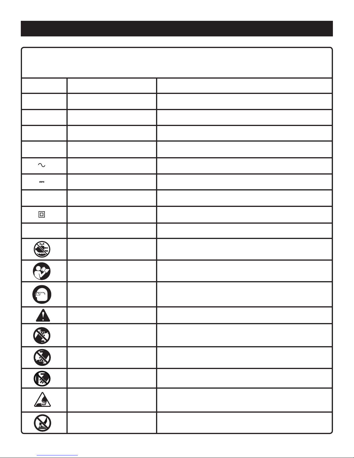
The laser guide radiation used in the laser level attachment
is Class IIIa with < 5mW and 635 nm wavelengths. These
lasers do not normally present an optical hazard, although
staring at the beam may cause flash blindness.
n Avoid direct eye exposure when using the laser and do
not project the laser beam directly into the eyes of others.
Serious eye injury could result.
n Do not remove or deface any product labels. Removing
product labels increases the risk of exposure to laser
radiation.
n Do not place the unit in a position that may cause anyone
to stare into the laser beam intentionally or unintentionally.
Serious eye injury could result.
n Do not operate the laser level around children or allow
children to operate the tool. Serious eye injury could re-
sult.
n Always turn the laser level off when not in use. Leaving
the tool on increases the risk of someone inadvertently
staring into the laser beam.
n Do not operate the unit in combustible areas such as in
the presence of flammable liquids, gasses, or dust.
n Always ensure the laser beam is aimed at a surface with-
out reflective properties. Shiny reflective materials are not
suitable for laser use.
n When using the base, always check to be sure the unit is
securely seated. Damage to the tool and/or serious injury
to the user could result if the unit falls.
n Handle the unit with care. Treat it as you would any other
optical device such as a camera or binoculars.
n Avoid exposing the unit to shock, continuous vibration,
or extreme hot or cold temperatures. Damage to the tool
and/or serious injury to the user could result.
n Save these instructions. Refer to them frequently and
use them to instruct others who may use this product. If
you loan someone this unit, loan them these instructions
also.

4 5
Some of the following symbols may be used on this tool. Please study them and learn their meaning. Proper interpreta-
tion of these symbols will allow you to operate the tool better and safer.
Read The Operator’s Manual
Safety Alert
No Hands Symbol
No Hands Symbol
No Hands Symbol
No Hands Symbol
SYMBOL NAME DESIGNATION/EXPLANATION
Voltage
Current
Frequency (cycles per second)
Power
Time
Type of current
Type or a characteristic of current
Rotational speed, at no load
Double-insulated construction
Revolutions, strokes, surface speed, orbits etc., per minute
Do not expose to rain or use in damp locations.
To reduce the risk of injury, user must read and understand
operator’s manual before using this product.
Eye Protection Always wear safety goggles, safety glasses with side shields, or
a full face shield when operating this product.
Precautions that involve your safety.
Failure to keep your hands away from the blade will result in
serious personal injury.
Failure to keep your hands away from the blade will result in
serious personal injury.
Failure to keep your hands away from the blade will result in
serious personal injury.
Failure to keep your hands away from the blade will result in
serious personal injury.
Wet Conditions Alert
.../min Per Minute
Class II Construction
n
o
No Load Speed
Direct Current
Alternating Current
min Minutes
W Watt
Hz Hertz
A Amperes
V Volts
Hot Surface To reduce the risk of injury or damage, avoid contact with any
hot surface.
SYMBOLS

4 5
SYMBOLS
SERVICE
This unit has no serviceable parts. If the unit fails due to
normal wear and tear within two years of purchase, return
with original receipt for a replacement unit at no charge. Call
1-800-525-2579 for your nearest AUTHORIZED SERVICE
CENTER.
WARNING:
To avoid serious personal injury, do not attempt to use this
product until you read thoroughly and understand com-
pletely the operator’s manual. Save this operator’s manual
and review frequently for continuing safe operation and
instructing others who may use this product.
SAVE THESE INSTRUCTIONS
The following signal words and meanings are intended to explain the levels of risk associated with this product.
SYMBOL SIGNAL MEANING
DANGER:
WARNING:
CAUTION:
CAUTION:
Indicates an imminently hazardous situation, which, if not avoided, will
result in death or serious injury.
Indicates a potentially hazardous situation, which, if not avoided, could
result in death or serious injury.
Indicates a potentially hazardous situation, which, if not avoided, may result
in minor or moderate injury.
(Without Safety Alert Symbol) Indicates a situation that may result in prop-
erty damage.

6 7
FEATURES
PRODUCT SPECIFICATIONS
Recommended Use .................................................................................................................................................... Indoors
Power Supply ........................................................................................................................ 3 AA, 1.5 Volt Alkaline Batteries
Battery Life for Laser With Vacuum.................................................................................................. 4 Hours Continuous Use
Battery Life for Laser Only.............................................................................................................. 40 Hours Continuous Use
Operating Temperature .................................................................................................................................... 32°F to 104°F
Laser.............................................................................................................................................. Class IIIa, < 5mW, 635 nm
Length of Laser Line.......................................................................................................................Up to 50 ft. each direction
Accuracy ........................................................................................................................................................± 1/4 in. at 50 ft.
Laser Coverage ...................................................................................... 260° in Static Position, Rotating Head Covers 360°
Fig. 1
ROUGH-SURFACE
ADAPTOR
LINE POSITION
ADJUSTMENT
THUMBWHEEL
ANGLE FINDER
LASER HEAD
LASER LENS
COVER
VACUUM BASE
ON / OFF BUTTON
AIRGRIP
VACUUM BASE
LASER
POWER / MODE
SELECTOR

6 7
KNOW YOUR SELF-LEVELING LASER
See Figures 1 - 2.
Before attempting to use this product, familiarize yourself
with all operating features and safety rules.
AIRGRIP™ VACUUM TECHNOLOGY
This product uses a vacuum base that can adhere to smooth
surfaces. Using the vacuum seal prevents wall damage
caused by nails or adhesive tape. The vacuum base also
features a 1/4 in. - 20 tripod mount.
ANGLE FINDER
Use the angle finder to dial in the specific angle desired.
CASE
A zippered fabric case stores and protects the laser level
when not in use.
HOOK-AND-LOOP STRAP
The hook-and-loop strap can be used along with the multi-
function base to attach the unit to a variety of irregularly
shaped surfaces.
LASER HEAD
The laser head on your level rotates 180˚ clockwise or coun-
terclockwise to allow for 360˚ of laser line coverage.
LASER LENS
Both laser lens rotate 90˚ to provide for horizontal level lines
or vertical plumb lines.
LASER POWER / MODE SELECTOR
The laser power/mode selector is used to select one of three
available operating modes — travel mode, self-leveling mode,
or angle-finder mode.
LINE POSITION ADJUSTMENT
THUMBWHEEL
The line position adjustment thumbwheel is used to fine tune
the laser line position with a range of 1 in.
MULTI-FUNCTION BASE
The multi-function base allows the laser level to be used on
irregularly shaped walls or objects. It features built-in loops
for a hook-and-loop strap and angled holes for push pins.
The base also protects the unit when using on a dusty or
dirty surface and during storage.
ROUGH-SURFACE ADAPTOR
The rough-surface adaptor increases the number of sur-
faces on which the AIRgrip vacuum can be used.
VACUUM BASE ON/OFF BUTTON
The vacuum base of your laser level conveniently turns on
and off at the touch of a button.
FEATURES
HOOK-AND-LOOP
STRAP
Fig. 2
PUSH PINS
MULTI-FUNCTION
BASE
CASE

8 9
ASSEMBLY
UNPACKING
This product has been shipped completely assembled.
n Carefully remove the tool and any accessories from the
box. Make sure that all items listed in the packing list are
included.
n Inspect the tool carefully to make sure no breakage or
damage occurred during shipping.
n Do not discard the packing material until you have care-
fully inspected and satisfactorily operated the tool.
n If any parts are damaged or missing, please call
1-800-525-2579 for assistance.
PACKING LIST
Self-Leveling Laser
Multi-Function Base
Rough-Surface Adaptor
Hook-and-Loop Strap
Push Pins (2)
AA Batteries (3)
Case
Operator’s Manual
WARNING:
If any parts are missing, do not operate this tool. Please
return to the place of purchase or call 1-800-525-2579
for assistance.
WARNING:
Do not attempt to modify this tool or create accesso-
ries not recommended for use with this tool. Any such
alteration or modification is misuse and could result in a
hazardous condition leading to possible serious personal
injury.
OPERATION
WARNING:
Do not allow familiarity with tools to make you care-
less. Remember that a careless fraction of a second is
sufficient to inflict serious injury.
WARNING:
Do not use any attachments or accessories not recom-
mended by the manufacturer of this tool. The use of at-
tachments or accessories not recommended can result
in serious personal injury.
APPLICATIONS
You may use this tool for the purposes listed below:
n Hanging pictures
n Projecting a laser line on adjacent and opposite walls
n Aligning electrical outlets or ceiling lights
n Leveling shelving or cabinetry
n Installing chair rail and crown molding
n Installing towel bars, curtains, etc.
n Mapping out drop ceilings

8 9
OPERATION
INSTALLING BATTERIES
See Figure 3.
The battery compartment is located on the bottom of the
vacuum base.
�n Squeeze the retaining clip on the battery cover plate to
release.
n Install three AA batteries according to polarity indicators
inside the battery compartment.
n Place the battery cover plate back onto the base and
push down until retaining clip snaps back into locked
position.
TURNING THE VACUUM BASE ON/OFF
See Figure 4.
Press the button located on the right side of the vacuum base
to turn it ON and OFF. Always wait for at least 5 seconds
between stopping and restarting the unit.
USING THE AIRGRIP VACUUM
See Figure 5.
Vacuum grip technology allows the unit to be attached to
most smooth surfaces.
NOTE: The multi-function base is not used when mounting
by vacuum grip.
n Place the unit on the surface you want it secured to and
press against the surface slightly to seal.
n Continue to hold the unit against the surface while press-
ing the on/off button.
n Release the unit when you hear a change in motor
sound.
NOTE: To release the vacuum seal, turn the power to the
vacuum base off. For fast release, press the protrusion on the
side of the AIRgrip seal. Pulling the unit off the wall without
releasing the vacuum could damage the tool.
TURNING THE LASER ON/OFF
See Figure 5.
The laser head has three different positions:
• Travel mode: laser is off, self-leveling is locked, angle
finder is locked.
• Self-leveling mode: laser is on, self-leveling is available,
angle finder is locked.
• Angle-finder mode: laser is on, self-leveling is locked,
angle finder is available.
When the angle indicator dial on the laser head is in the
center, the laser head is in travel mode. For self-leveling
mode, turn the dial to the right. Turn the dial to the left for
angle-finder mode.
Fig. 3
Fig. 4
Fig. 5
BATTERY
COVER
PLATE
RETAINING CLIP
VACUUM
BASE
ON/OFF
BUTTON
ANGLE INDICATOR DIAL
VACUUM
BASE ON/OFF
BUTTON
SELF-LEVELING
MODE
ANGLE-FINDER
MODE
TRAVEL
MODE

10 11
OPERATION
NOTE: The laser head should be kept in travel mode when
carrying the unit or whenever the unit will not be used for
an extended period.
ROUGH-SURFACE ADAPTOR
See Figure 6.
By using the rough-surface adaptor, you can use the AIRgrip
feature to position the unit on many non-smooth surfaces,
including brick and painted cinder block.
NOTE: The AIRgrip feature cannot be used with stucco or
unpainted cinder block.
n Position the rough-surface adaptor on the surface where
you want to secure the vacuum base.
NOTE: Dotted lines on the adaptor should be visible.
n Place the unit against the adaptor on the dotted lines, and
press against the surface slightly to engage the seal.
n Continue to hold the unit against the surface while press-
ing the on/off button.
n Release the unit when you hear a change in motor
sound.
USING THE MULTI-FUNCTION BASE
See Figure 7.
Hook-and-loop strap and push pin mounting methods are
available only when the multi-function base is installed.
To install the base:
n While holding the laser level with the power button facing
you, align the raised ridge on the base with the groove
on the level.
n Slide the laser level and base completely together.
HOOK-AND-LOOP STRAP: The hook-and-loop strap can
be used to attach the laser level to irregularly shaped objects
such as pipes, 2x4s, 2x6s, or metal grates.
n Attach the strap to one side of the multi-function base
by threading it through the loop and fastening.
n Position the laser level on the surface where you want it
mounted.
n Wrap the strap around the object being mounted (pipe,
board, etc.).
n Place the loose end of the strap through the remaining
loop on the multi-function base and secure.
PUSH PINS: Push pins allow the laser level to be mounted
to stucco and permeable surfaces.
Fig. 7
ROUGH-SURFACE
ADAPTOR
HOOK-AND-LOOP
STRAP
LOOP
ANGLED HOLE
Fig. 6
n Place the laser level on the surface where you want it
mounted.
�n Align push pins with angled holes in the base and push
in to secure.
CAUTION:
Use caution when using the multi-function base. Do not
orient the unit in a way that will allow the vacuum base
to slide or fall out of the multi-function base.

10 11
1
2
"
OPERATION
TRIPOD MOUNTING
See Figure 8.
The laser level vacuum base has a standard 1/4 in.-20
threaded fitting for attaching to a tripod (not included). This
method of mounting is ideal for leveling kitchen cabinets,
countertops, window framing, and more.
ADJUSTING THE LASER LINE
See Figure 8 - 9.
The laser level will project a straight line across an obstruction
or interference, as well as around inside corners and onto
adjacent surfaces. The line can be adjusted in three ways:
�n The line can be rotated by turning the laser head in a
clockwise or counterclockwise direction to achieve full
360° coverage.
�n The line can be rotated up to 90°, from vertical to hori-
zontal, by rotating the laser head away from the mounting
surface.
n The line can also be rotated 90° by lifting the lens cover
and turning the lens in a clockwise or counterclockwise
direction.
OPERATING THE LASER LEVEL
See Figures 9 - 11.
�n Place the level in the area where you want the laser line
projected. Refer to Using the AIRgrip Vacuum earlier in
this manual if adhering to a surface is desired.
��n Turn on the laser.
n Rotate the laser head to position the laser line as de-
sired.
NOTE: The line position adjustment thumbwheel can
be used to adjust the laser line ± 1/2 in. Turn the wheel
clockwise to move the laser line slightly down, or coun-
terclockwise to move the line slightly up. A measurement
scale is marked on the base for reference.
��n For best self-leveling results, always position laser head
so that face of angle indicator dial is perpendicular to the
direction of gravity.
NOTE: Due to construction inaccuracy, walls may not be
perfectly straight. This may cause the laser to have slight
variances when in the level position.
Fig. 9
Fig. 10
LASER HEAD LENS
COVER
LASER
LENS
HORIZONTAL
LASER LINE
Fig. 8
LASER LEVEL
MOUNTED ON
TRIPOD
LINE POSITION ADJUSTMENT
THUMBWHEEL
SCALE
GRAVITY

12 13
OPERATION
FULL-ROOM COVERAGE: The unit will project a line out each
end of the laser head at an approximate angle of 130˚ each
way for a total of 260˚. To cover the remainder of the work
area with a level line, turn the laser head as far as 180˚.
SELF-LEVELING MODE: If horizontal lines are desired, use
the self-leveling mode to allow the unit to automatically level.
The LED indicator located next to the thumbwheel will light
if the unit is out of level. Reposition the laser head to within
± 5˚ of the horizontal plane to allow the self-leveling feature
of the level to properly function.
ANGLE-FINDER MODE: The dial indicator on top of the
laser head is an angle finder. It allows any degree angle to
be projected by the unit. To use the angle-finder:
��n Turn the laser head dial to the left to lock out the self-
leveling feature.
��n Move the laser head downward, away from the wall.
��n Wait until the arrow on the dial is pointing downward at
0˚.
��n Move the laser head to the desired angle. The scale is
graduated in 5˚ increments.
NOTE: Unit will not self-level when face of angle indicator
dial is parallel to direction of gravity.
Fig. 11
DIAL INDICATOR
ANGLE FINDER
ROTATE DIAL
LEFT FOR
ANGLE-FINDER
MODE
DOWN ARROW
INDICATES 0°
ROTATE LASER HEAD
FOR FULL-ROOM
COVERAGE
ROTATE DIAL
RIGHT FOR
SELF-LEVELING
MODE
OUT OF LEVEL
LED INDICATOR
GRAVITY

12 13
MAINTENANCE
WARNING:
To avoid serious personal injury, always remove the
batteries from the tool when cleaning or performing any
maintenance.
GENERAL MAINTENANCE
n Before initial use, wipe AIRgrip vacuum base with a damp
cloth to remove any residue.
n Store the unit indoors.
n When not in use, the vacuum base and attachments
should be kept in the protective case.
n Keep the unit free of dust and liquids. Use a damp cloth
and mild soap to clean the outside casing. Avoid using
solvents when cleaning plastic parts. Most plastics are
susceptible to damage from various types of commercial
solvents and may be damaged by their use.
�n To clean the laser lens, if needed, use ONLY a soft cloth
or cotton swab moistened with glass cleaner.
n Check the batteries regularly to avoid deterioration. Re-
move the batteries from the vacuum base if you will not
be using them for an extended time.
�n Do not disassemble the laser level. This could cause
exposure to hazardous laser radiation.
n Do not attempt to change any part of the laser lens.
WARNING:
Do not at any time let brake fluids, gasoline, petroleum-
based products, penetrating oils, etc., come in contact
with plastic parts. Chemicals can damage, weaken, or
destroy plastic, which may result in serious personal
injury.
ALWAYS BE AWARE of the location
where the laser light is emitted when
using the laser level attachment. AL-
WAYS MAKE SURE that any bystanders
in the vicinity of use are made aware of
the dangers of looking directly into the
laser beam.
TROUBLESHOOTING
Problem Possible Cause Solution
Vacuum not running Batteries are low
Power is turned off
Replace batteries.
Press on/off button.
Laser line projection is weak Batteries are low Replace batteries.
Laser line is hard to see Light in area is too bright Dim light in the work area or use laser-
enhancing glasses.
Light is not working Power is not “on”
Batteries are low
Press the on/off button.
Replace batteries.
Light is dim Batteries are low Replace batteries.
Vacuum base won’t stick to wall Surface is incompatible for vacuum Use rough-surface adaptor on stucco
and textured surfaces.

14
RYOBI TECHNOLOGIES, INC.
1428 Pearman Dairy Road, Anderson, SC 29625
Post Office Box 1207, Anderson, SC 29622-1207
Phone 1-800-525-2579
www.ryobitools.com
983000-802
7-05
• SERVICE
This product has no serviceable parts. If unit fails due to normal wear and tear within two
years of purchase, return with original receipt for a replacement unit at no charge. Please
call 1-800-525-2579 for the nearest Authorized Service Center. You can also check our
web site at www.ryobitools.com for a complete list of Authorized Service Centers.
• MODEL NO.
The model number of this tool will be found on a label attached to the laser level. Please
go to www.ryobitools.com to register this product.
• HOW TO ORDER REPLACEMENT PARTS
When ordering replacement parts, always give the following information:
• MODEL NUMBER ELL0002
OPERATOR’S MANUAL
AIRgrip™ Self-Leveling Laser
ELL0002
Ryobi® is a registered trademark of Ryobi® Limited used under license.
Table of contents
Other Ryobi Laser Level manuals

Ryobi
Ryobi AIRgrip MultiTASKit EMM0001 User manual

Ryobi
Ryobi RB360GLL User manual

Ryobi
Ryobi ELL1750 User manual

Ryobi
Ryobi ELL1500 User manual

Ryobi
Ryobi CLL-100 Operation manual

Ryobi
Ryobi RBCLLG1 User manual

Ryobi
Ryobi TLL-90 Operation manual

Ryobi
Ryobi AirGrip ELL1001 User manual

Ryobi
Ryobi AIRgrip RLAG113S User manual

Ryobi
Ryobi LSL-100 Operation manual

Ryobi
Ryobi AIRgrip ELL0001 User manual

Ryobi
Ryobi AirGrip ELL1001 User manual

Ryobi
Ryobi ELL1501 User manual

Ryobi
Ryobi PHONEWORKS ES1600 User manual

Ryobi
Ryobi ELL1002 User manual

Ryobi
Ryobi AIRgrip ProCross ELL0006 User manual

Ryobi
Ryobi CLL-360 Operation manual

Ryobi
Ryobi RLL10RD User manual

Ryobi
Ryobi RBCLLG2 User manual

Ryobi
Ryobi ELL1500 User manual