Ryobi APR-03 User manual

TM
APR-03
PRUNER ATTACHMENT
OPERATOR’S MANUAL

1
2
3
4
5
6
7
Fig. 1
12
5
13
14
9
10
11
Fig. 2

Fig. 3
Fig. 4
Fig. 5 Fig. 6
Fig. 7 Fig. 8
Fig. 9 Fig. 10
19
15
16
17
18
B
A
C
20

Fig.12
Fig. 16
Fig. 17
2121 22
22
23
21
24
25
126
27
228
25
21
29
21
30
Fig. 15
Fig. 14
Fig. 13
Fig. 11
Fig. 18

Fig. 20
Fig. 21
Fig. 22
Fig. 25
Fig. 26
Fig. 27
3
32
34
35
36
38
39
40
41
37
43
42
8
33
12
5
A
Fig. 19
31
Fig. 23
Fig. 24

Important!
It is essential that you read the instructions in this
manual before mounting and operating this machine.
Subject to technical modifications

Your Expand-it™ Pruner Attachment has been engineered and manufactured to our high standards for dependability, ease of
operation, and operator safety. When properly cared for, it will give you years of rugged, trouble-free performance.
WARNING
To reduce the risk of injury, the user must read and understand the operator’s manual before using this product.
Thank you again for buying an Expand-it™ Accessory.
SAVE THIS MANUAL FOR FUTURE REFERENCE
INTRODUCTION
INTRODUCTION
This product has many features for making its use more pleasant and enjoyable. Safety, performance, and dependability have
been given top priority in the design of this product making it easy to maintain and operate.
1
English

WARNING
READ AND UNDERSTAND ALL INSTRUCTIONS.
Failure to follow all instructions listed below,
may result in electric shock, fire and/or serious
personal injury.
SAVE THESE INSTRUCTIONS.
GENERAL SAFETY RULES
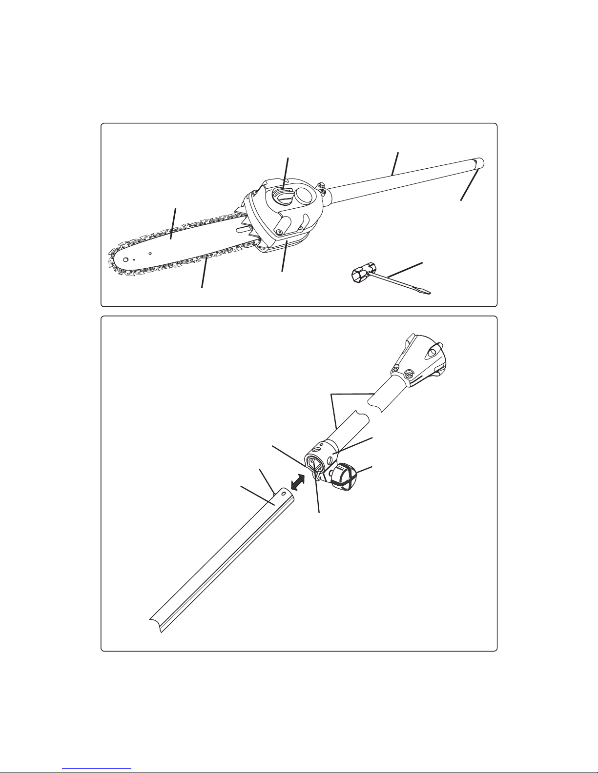
■For safe operation, read and understand all instructions
before using the straight shaft trimmer attachment. Follow
all safety instructions. Failure to follow all safety
instructions listed below, can result in serious personal
injury.
■Do not allow children or untrained individuals to use this
unit.
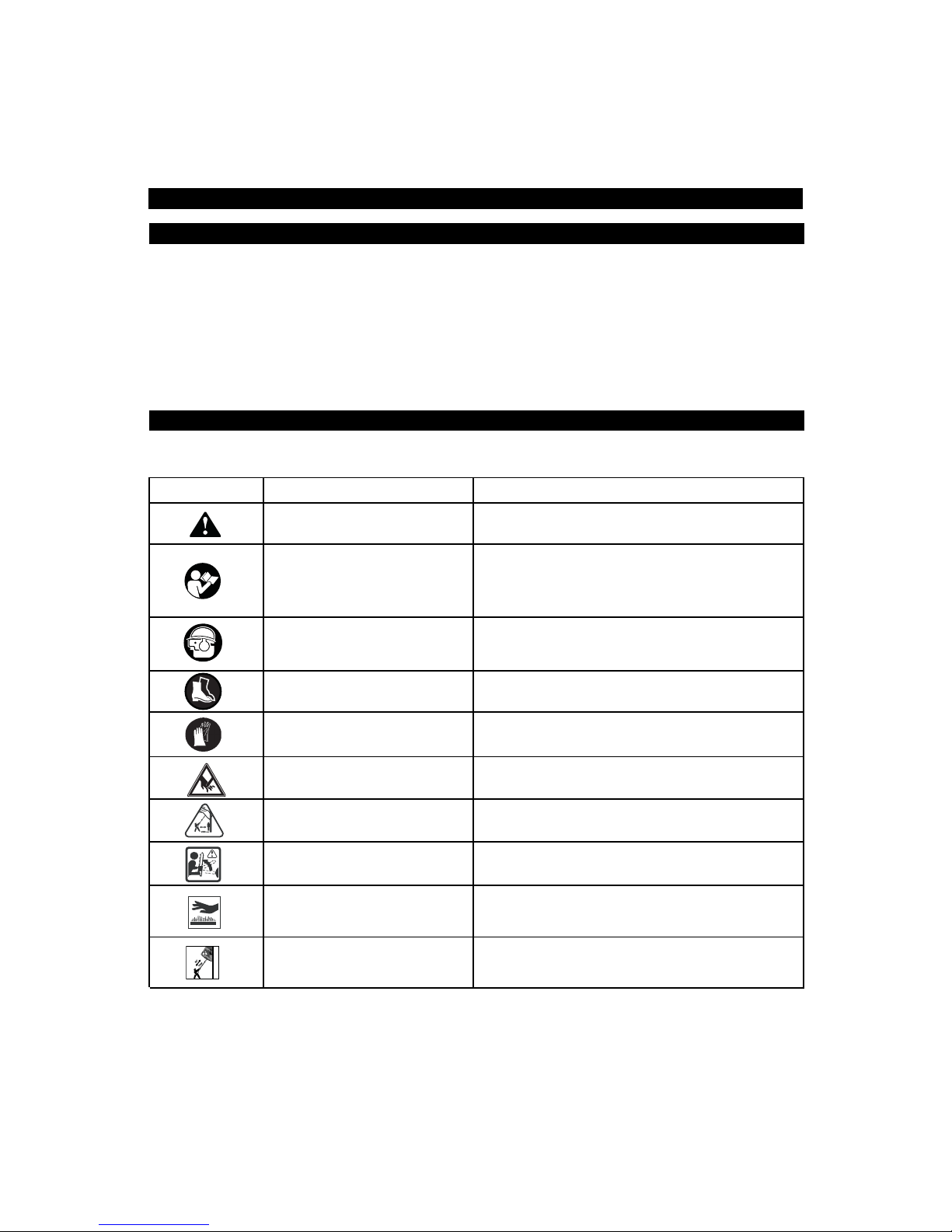
■Wear safety glasses or goggles that are marked to comply
with ANSI Z87.1 standards and hearing protection when
operating this unit.
■Wear heavy long pants, boots, and gloves. Do not wear
loose fitting clothing, short pants, jewelry of any kind, or
go barefoot.
■Secure long hair so it is above shoulder level to prevent
entanglement in any moving parts.
■Keep all bystanders, children, and pets at least
15 m away.
■Do not operate this unit when you are tired, ill,
or under the influence of alcohol, drugs, or medication.
■Do not operate in poor lighting.
■Keep firm footing and balance. Do not overreach.
Overreaching can result in loss of balance or exposure to
hot surfaces.
■Keep all parts of your body away from any moving part.
■Do not touch areas around the muffler or cylinder of the
power head, these parts get hot from operation. Failure to
do so could result in possible serious personal injury.
■Always stop the engine and remove the spark plug wire
before making any adjustments or repairs except for
carburetor adjustments.
■Inspect unit before each use for loose fasteners, damaged
or missing parts. Correct before using the straight shaft
trimmer attachment. Failure to do so can cause serious
injury.
■Check for damaged parts. Before further use of the
appliance, any part that is damaged should be carefully
checked to determine that it will operate properly and
perform its intended function. Check for alignment of
moving parts, binding of moving parts, breakage of parts,
mounting, and any other conditions that may affect its
operation. A guard or other part that is damaged should
be properly repaired or replaced by an authorized service
center.
■Use only original manufacturer’s replacement parts.
Failure to do so, may cause poor performance, possible
injury, and will void your warranty.
■Do not, under any circumstance, use any attachment or
accessory on this product which was not provided with the
product or identified as appropriate for use with this
product in the Operator’s Manual.
SPECIFIC SAFETY RULES FOR PRUNER USE
■Kickback is a dangerous reaction that can lead to serious
injury. Kickback may occur when the moving chain
contacts an object at the upper portion of the tip of the
guide bar or when the wood closes in and pinches the
saw chain in the cut. Contact at the upper portion of the tip
of the guide bar can cause the chain to dig into the object
and stop the chain for an instant. The result is a lightning
fast, reverse reaction which kicks the guide bar up and
back toward the operator. If the saw chain is pinched
along the top of the guide bar, the guide bar can be driven
rapidly back toward the operator. Either of these reactions
can cause loss of saw control which can result in serious
injury. Do not rely exclusively upon the safety devices built
into your saw. As a chain saw user,
you should take several steps to keep your cutting jobs
free from accident or injury.
■With a basic understanding of kickback, you can reduce or
eliminate the element of surprise. Sudden surprise
contributes to accidents.
■Make sure that the area in which you are cutting is free
from obstructions. Do not let the nose of the guide bar
contact a log, branch, fence, or any other obstruction
while you are operating the unit.
■Always cut with the engine running at full speed. Fully
squeeze the throttle trigger and maintain a steady cutting
speed.
■Follow the sharpening and maintenance instructions for
the saw chain.
■Use only the replacement guide bars and low kickback
chains specified for your unit.
■Do not force tool. Use the correct tool for your application.
The correct tool will do the job better and safer at the rate
for which it is designed.
■Do not use on a ladder or unstable support.
■Never let anyone use your machine who has not received
adequate instructions in the machine's proper use.
This applies to rentals as well as private owned units and
also to the power head it is attached to.
■To protect yourself from electrocution, do not operate
within 50 feet (15 m) of overhead electrical lines.
■To protect yourself from falling branches, do not stand
directly under the branch or limb being cut. This unit
should not be held at an angle over 60° from ground level.
■Keep the handles dry, clean, and free of oil or fuel mixture.
2
English
SAFETY RULES

■Before you start the engine, make sure the chain is not
contacting any object.
■Shut off the engine and make sure the cutting attachment
has stopped before setting the unit down.
■To prevent electrical shock or serious personal injury,
do not use this product with any AC power head.
3
English
SAFETY RULES
SYMBOLS
Important: Some of the following symbols may be used on your unit. Please study them and learn their meaning.
Proper interpretation of these symbols will allow you to operate the tool better and safer.
SYMBOL NAME EXPLANATION
Safety Alert Symbol Indicates danger, warning or caution.
It means attention!!! Your safety is involved.
Read Your Operator’s Manual Your manual contains special messages to bring attention to
potential safety concerns, machine damage as well as helpful
operating and servicing information. Please read all the
information carefully to avoid injury and machine damage.
Wear eye, hearing, and Wear eye protection which is marked to comply with
head protection ANSI Z87.1 as well as hearing and head protection when
operating this equipment.
Safety footwear Wear non-slip safety footwear when using this equipment.
Wear gloves Wear non-slip, heavy-duty protective gloves when handling
the pole pruner attachment and the saw chain.
Moving parts Keep hands away from moving parts.
Keep bystanders away Keep all bystanders at least 50 ft. (15 m) away.
Kickback DANGER! Beware of kickback.
Hot surfaces Indicates HOT SURFACES. Keep all body parts away from
all hot surfaces.
Risk of Electrocution DANGER! Risk of electrocution!
50' 15m

SYMBOLS
The following signal words and meanings are intended to explain the levels of risk associated with this product.
SYMBOL SIGNAL MEANING
DANGER Indicates an imminently hazardous situation which, if not avoided, will result in
death or serious injury.
WARNING Indicates a potentially hazardous situation which, if not avoided, could result in
death or serious injury.
CAUTION Indicates a potentially hazardous situation which, if not avoided, may result in
minor or moderate injury.
CAUTION (Without Safety Alert Symbol) Indicates a situation that may result in property
damage.
WARNING
The operation of any product can result in foreign objects being thrown into your eyes, which can result in
severe eye damage. Before beginning operation, always wear safety goggles or safety glasses with side
shields and a full face shield when needed. We recommend Wide Vision Safety Mask for use over eyeglasses
or standard safety glasses with side shields. Always wear eye protection which is marked to comply with
ANSI Z87.1.
SAVE THESE INSTRUCTIONS
4
English
SERVICE
Servicing requires extreme care and knowledge and should
be performed only by a qualified service technician.
For service we suggest you return the product to your
nearest AUTHORIZED SERVICE DEALER for repair.
When servicing, use only identical replacement parts.
WARNING
To avoid serious personal injury, do not attempt to
operate this product until you read thoroughly and
understand completely the operator's manual.
Save this operator's manual and review frequently for
continuing safe operation and instructing others who
may use this product.

1. BAR
2. CHAIN
3. CHAIN OILER TANK CAP
4. GEAR CASE
5. PRUNER ATTACHMENT SHAFT
6. END CAP
7. COMBINATION WRENCH
8. HANGER CAP
9. KNOB
10. COUPLER
11. POWER HEAD SHAFT
12. BUTTON
13. GUIDE RECESS
14. POSITIONING HOLE
15. SHOULDER STRAP HANGER
16. STRAP HANGER
17. BOLT
18. LOCK WASHER
19. NUT
20. CUTTING GUIDE
21. BAR NUT
22. DRIVE CASE COVER
23. CHAIN TENSIONING PIN
24. BAR STUD
25. SPROCKET
26. BAR STUD SLOT
27. CHAIN TENSIONING PIN HOLE
28. CHAIN ROTATION
29. CHAIN TENSIONING SCREW
30. IDLE SPEED SCREW
31. CHAIN OILER TANK
32. DEPTH GAUGE SETTING
33. HANGER HOLE
34. TOP PLATE
35. RIVET HOLE
36. HEEL
37. GULLET
38. CUTTING CORNER
39. SIDE PLATE
40. DEPTH GAUGE
41. TOE
42. LEFT HAND CUTTERS
43. RIGHT HAND CUTTERS
5
English
FEATURES
DESCRIPTION
Before attempting to use this product, familiarize yourself with
all operating features and safety rules.
See Figure 1.
WARNING
Do not allow familiarity with your tool to make you
careless. Remember that a careless fraction of a
second is sufficient to inflict severe injury.
WARNING
Do not attempt to modify this tool or create
accessories not recommended for use with this tool.
Any such alteration or modification is misuse and
could result in a hazardous condition leading to
possible serious personal injury.

JOINING THE POWER HEAD TO THE ATTACHMENT
See Figure 1 and 2.
WARNING
Never attach or adjust any attachment while power
head is running. Failure to stop the engine may cause
serious personal injury.
The attachment connects to the power head by means of a
coupler device.
1. Loosen the knob (9) on the coupler (10) of the power head
shaft and remove the end cap (6) from the attachment
shaft (5).
2. Push in the button located on the attachment shaft. Align
the button with the guide recess (13) on the power head
coupler and slide the two shafts together. Rotate the
attachment shaft until the button locks into the positioning
hole (14).
Note: If the button does not release completely in the
positioning hole, the shafts are not locked into place.
Slightly rotate from side to side until the button is locked
into place.
3. Tighten the knob securely.
Note:If the buttons do not release completely in the
positioning holes, the shafts are not locked into place.
Slightly rotate from side to side until the button is locked
into place.
Note: The pole pruner attachment should only be
operated with the blade in a vertical position. Use only the
specified positioning hole for this pole pruner attachment.
WARNING
Be certain the knob is fully tightened before operating
equipment; check it periodically for tightness during
use to avoid serious injury.
CHAIN OILER
Add bar and chain oil in the chain oiler tank (31) before
starting the engine of the power head.
REMOVING THE ATTACHMENT FROM THE POWER
HEAD
For removing or changing the attachment:
1. Loosen the knob.
2. Push in the button and twist the shafts to remove and
separate ends.
INSTALLING THE SHOULDER STRAP AND
HANGER
See Figure 3 and 4.
When operating this unit, you must wear a shoulder strap to
support the unit. If you unit does not have a strap hanger
installed on the power head shaft, use the following
instructions to install the hanger.
1. Pull strap hanger (16) apart and place over power head
end of shaft, position near the upper knob.
2. Install bolt (17), lock washer (18), and nut (19). Tighten nut
securely.
Note: Check for tightness before each use to avoid
serious injury or product damage.
3. Place shoulder strap over your left shoulder and attach clip
(15) to strap hanger.
4. Shoulder strap can be adjusted by sliding the clip up
or down.
5. When properly adjusted, the power head should be
supported by the shoulder strap about hip level.
6
English
ASSEMBLY
OPERATION
POSITION FOR STARTING
See Figure 5.
Lay the pole pruner on the ground and ensure that no objects
or obstructions are in the immediate vicinity. Make sure
nothing can come in contact with the bar and chain.
WARNING
To avoid kickback, binding of the saw bar, and
possible injury, never cut limbs that the pole pruner
does not reach when supported by the shoulder strap.
PREPARATION FOR CUTTING
PROPER GRIP ON HANDLES
Refer to the “Important Safety Instructions” earlier in this
manual, for appropriate safety equipment.
■Wear non-slip gloves for maximum grip and protection.
■Maintain a proper grip on the unit whenever the engine is
running. Use your right hand to firmly grip the rear handle
while your left hand has a firm grip on the front handle.
■Hold the unit firmly with both hands. Always keep your left
hand on the front handle and your right hand on the rear
handle, so that your body is to the left of the chain line.
Never use a left-handed (cross-handed) grip, or any
stance which would place your body or arm across the
chain line.
See Figure 6.
■Never stand directly under the limb you are cutting.
See Figure 6.
■Always wear shoulder strap for increased safety and to
support the pole pruner.

BASIC CUTTING PROCEDURE
■Accelerate the engine to full throttle just before entering
the cut by squeezing the throttle trigger.
■DO NOT use a back and forth sawing type motion for
cutting.
■The following steps should be followed to prevent damage
to tree or shrub bark.
See Figure 7.
1. The first cut should be a shallow cut (1/4 of the limb
diameter) on underside of limb close to main limb or
trunk (A).
2. The second cut should be made from the top side of the
limb out wards from first cut (B).
3. Make the final cut close to trunk (C).
WARNING
To prevent possible serious injury to yourself or to
others, READ, understand, and follow all instructions
in this Operator's Manual.
■Keep the engine at full throttle the entire time you are
cutting.
■For second and final cuts (from top of limb or branch),
hold the front cutting guide (20) against the limb being cut.
See Figure 8.
This will help steady the limb and make it
easier to cut.
■Allow the chain to cut for you; exert only light downward
pressure. If you force the cut, damage to the bar, chain,
or engine can result.
■Release the trigger as soon as the cut is completed,
allowing the engine to idle. If you run the pole pruner at full
throttle without a cutting load, unnecessary wear or
damage can occur to the chain, bar, and engine.
WORK AREA PRECAUTIONS
■Cut only wood or materials made from wood; no sheet
metal, no plastics, no masonry, no non-wood building
materials.
■Never allow children to operate your pole pruner. Allow no
person to use this pole pruner who has not read this
Operator's Manual and received adequate instructions for
the safe and proper use of this pole pruner.
■Keep everyone - helpers, bystanders, children, and
animals a safe distance, of at least 50 ft. (15 m), from the
cutting area.
■Always cut with both feet on solid ground to prevent being
pulled off balance.
■Cut only when visibility and light are adequate for you to
see clearly.
LIMBING AND PRUNING
This unit is designed for trimming small branches and limbs
up to 6 in. (15 cm) in diameter.
■Plan the cut carefully. Be aware of the direction in which
the branch will fall.
■Branches may fall in unexpected directions. Do not stand
directly under the branch being cut.
■The most typical cutting application is to position the unit
at an angle of 60° or less, depending on the specific
situation.
See Figure 9.
■As the angle of the pole pruner shaft to ground increases,
the difficulty of making the first cut (from the underside
of limb) increases. Failure to follow procedure shown
in Figure 7 will result in the bar and chain binding
and becoming pinched or trapped in the limb. If this
should happen:
1. Stop the engine of the power head.
2. With engine stopped, loosen the knob on coupler.
3. Depress the button on the shaft, twist and pull the
shafts to separate the pruner from the engine.
4. If the limb can be reached from the ground, lift the limb
while holding the attachment. This should release the
"pinch" and free the pruner.
5. If pruner is still trapped, call a professional for
assistance.
■The long reach of the unit allows the operator to prune
branches or limbs that are normally out of reach.
■Long branches should be removed in several stages.
■Cutting lower branches first will allow the top branches
more room to fall.
■Work slowly, keeping both hands on the saw with
a firm grip. Maintain secure footing and balance.
■Keep the tree between you and the chain while limbing.
Cut from the side of the tree opposite the branch you
are cutting.
■Do not cut from a ladder, this is extremely dangerous.
Leave this operation for professionals.
■DO NOT use for felling or bucking.
■When pruning trees it is important not to make the flush
cut next to the main limb or trunk until you have cut off the
limb further out to reduce the weight. This prevents
stripping the bark from the main member. Under cut the
the branch 1/4 way through for your first cut, your second
cut should an over cut to drop the branch off. Now make
your final cut smoothly and neatly against the main
member so the bark will grow back to seal the wound.
See
Figure 7.
■Keep all bystanders at least 50 ft. (15 m) away. To prevent
electrocution, do not operate within 50 feet (15 m) of
overhead electrical lines.
See Figure 11.
Under-Cut
Begin on the under side of the limb with the top of the pruner
against the limb; exert light pressure upward. During
underbucking, the pruner will tend to push back at you.
Be prepared for this reaction and hold the pruner firmly to
maintain control.
7
English
OPERATION

Over-Cut
Begin on the top side of the limb with the bottom of the
pruner against the limb; exert light pressure downward.
Note that the pruner will tend to pull away from you.
WARNING
To prevent electrocution, do not operate within 50 feet
(15 m) of overhead electrical lines.
See Figure 11.
WARNING
Keep all bystanders at least 50 ft. (15 m) away.
See Figure 11.
WARNING
Never climb into a tree to limb or prune. Do not stand
on ladders, platforms, a log or in any position which can
cause you to lose your balance or control of the unit.
8
English
OPERATION
MAINTENANCE
■Never operate a unit that is damaged, improperly
adjusted, or is not completely and securely assembled.
Be sure that the saw chain stops moving when the trigger
is released. If the chain moves at idle speed, the
carburetor may need adjusting, refer to “Maintenance-
Trimmer Engine – Idle Speed Adjustment” later in this
manual. If the chain still moves at idle speed after
adjustment has been made, contact a service dealer for
adjustment and discontinue use until the repair is made.
■Always stop the engine and remove the spark plug wire or
disconnect from power supply before making any
adjustments or repairs except for carburetor adjustments.
■Inspect unit before each use for loose fasteners, fuel leaks
and damaged parts. Replace any parts that are cracked,
chipped, or damaged in any way. Failure to do so can
cause serious injury.
■Make sure all handles are properly and securely attached.
■Never modify the unit in any way. Do not use for any
purpose except that for which it is intended.
■Keep all safety devices in place when using this machine.
Failure to do so can cause serious injury.
WARNING
Use only the manufacturer's replacement parts.
Failure to do so may cause poor performance,
possible injury and may void your warranty.
■Before storing the unit, allow the engine to cool. Always
place the sheath on the saw bar when transporting or
storing your pole pruner. The sheath is a snug fit and must
be attached very carefully due to the sharp teeth on the
saw chain. This is best done by grasping the sheath at
one end, in the center portion of the sheath, and carefully
sliding it over the chain. Use caution to avoid the sharp
teeth of the chain.
See Figure 11.
REPLACING THE BAR AND CHAIN
WARNING
To avoid possible serious injury, stop engine
before replacing the bar, chain, or performing any
maintenance operation.
See Figures 12 and 13.
1. Remove the bar nut and drivecase cover, using the
combination wrench provided.
2. The bar contains a bar stud slot that fits over the bar stud.
The bar also contains a chain tensioning pin hole which fits
over the chain tensioning pin.
See Figures 14 and 15.
3. Place the bar onto the bar stud so that the chain tensioning
pin fits into the chain tensioning pin hole.
4. Fit the chain over the sprocket and into the bar groove. The
cutters on the top of the bar should face toward the bar tip,
in the direction of the chain rotation.
5. Replace the side case cover and install the bar nut. Tighten
the bar nut finger tight only, the bar must be free to move
for tension adjustment.
6. Remove all slack from chain by turning the chain
tensioning screw (29) clockwise, assuring that the chain
seats into the bar groove during tensioning.
See Figure 16.
7. Lift the tip of the bar up to check for sag. Release the tip
of the bar, and turn the chain tensioning screw 1/2 turn
clockwise. Repeat this process until sag does not exist.
8. Hold the tip of the bar up and tighten the bar nut securely.
See Figure 17.
9. Chain is correctly tensioned when there is no slack on the
underside of the bar, the chain is snug, but it can be turned
by hand without binding.
Note: If chain is too tight, it will not rotate. Loosen the
bar nut slightly and turn adjusting screw 1/4 turn counter-
clockwise. Lift the tip of the bar up and retighten
bar nut.
WARNING
Check the chain tension frequently when operating
the unit. Never touch or adjust the chain while the
engine is running. The chain is very sharp, always
wear protective gloves when performing maintenance
to the chain.

TRIMMER ENGINE - IDLE SPEED ADJUSTMENT
See Figure 18.
If the chain turns at idle, the idle speed screw needs
adjusting on your trimmer engine. Turn the idle speed screw
counterclockwise to reduce the idle RPM and stop the chain
movement. If the saw chain still moves at idle speed, contact
a service dealer for adjustment and discontinue use until the
repair is made.
WARNING
The saw chain should never turn at idle. Turn the idle
speed screw “T” counterclockwise to reduce the idle
RPM and stop the chain, or contact a service dealer
for adjustment and discontinue use until the repair is
made. Serious personal injury may result from the saw
chain turning at idle.
CHAIN TENSION
WARNING
To avoid possible serious injury, never touch or adjust
the chain while the motor is running. The saw chain is
very sharp, always wear protective gloves when
performing maintenance to the chain.
1. Stop the engine before setting the chain tension. Make
sure the guide bar nut is loose to finger tight, turn the chain
tensioning screw clockwise to tension the chain. Refer to
“Replacing the Bar and Chain” for additional information.
A cold chain is correctly tensioned when there is no slack
on the underside of the guide bar, the chain is snug, but it
can be turned by hand without binding.
2. Chain must be re-tensioned whenever the flats on the drive
links hang out of the bar groove.
See Figure 19.
3. During normal operation, the temperature of the chain
will increase. The drive links of a correctly tensioned warm
chain will hang approximately .050 in. (1.25 mm) out of the
bar groove.
See Figure 20.
Note: New chain tends to stretch; check chain tension
frequently and tension as required.
CAUTION
Chain tensioned while warm, may be too tight upon
cooling. Check the "cold tension" before next use.
CHAIN OILER
1. Use Premium Bar and Chain Oil. It is designed for chains
and chain oilers and is formulated to perform over a wide
temperature range with no dilution required.
2. Remove the cap (3) and carefully pour approximately 8 oz.
(237 cc) of the bar and chain oil into the chain oiler tank
(31).
See Figure 21.
3. Replace the cap and tighten securely.
4. Check and refill the chain oiler tank every time the engine
is fueled.
Note: Do not use dirty, used or otherwise contaminated oils.
Damage may occur to the oil pump, bar, or chain.
CHAIN MAINTENANCE
Use only the replacement low kickback chain specified
for your unit.
For smooth and fast cutting, the chain needs to be
maintained properly. The chain requires sharpening when the
wood chips are small and powdery, the chain must be
forced through the wood during cutting, or the chain cuts
to one side. During maintenance of your chain, consider
the following:
■Improper filing angle of the side plate can increase the
risk of a severe kickback.
■Depth gauge (or raker clearance) setting (32) determines
the height the cutter enters the wood and the size of the
wood chip that is removed. Too much clearance increases
the potential for kickback. Too little clearance decreases the
size of the wood chip thus decreasing the chain's
cutting ability.
See Figure 22.
■If cutter teeth have hit hard objects such as nails
and stones, or have been abraded by mud or sand on
the wood, have service dealer sharpen chain.
HOW TO SHARPEN THE CUTTERS
See Figure 23.
Be careful to file all cutters to the specified angles and to the
same length, as fast cutting can be obtained only when all
cutters are uniform.
1. Tighten the chain tension enough that the chain does
not wobble. Do all of your filing at the mid-point of the bar.
Wear gloves for protection.
2. Use a 5/32 in. (4.5 mm) diameter round file and holder.
3. Keep the file level with the top plate of the tooth. Do not let
the file dip or rock.
See Figure 24.
4. Using light but firm pressure, stroke towards the front
corner of the tooth. Lift file away from the steel on each
return stroke.
See Figure 25.
5. Put a few firm strokes on every tooth. File all left hand
cutters (42) in one direction. Then move to the other side
and file the right hand cutters (43) in the opposite direction.
Occasionally remove filings from the file with a wire brush.
See Figure 26.
CAUTION
Dull or improperly sharpened chain can cause
excessive engine speed during cutting which may
result in severe engine damage.
9
English
MAINTENANCE

WARNING
Improper chain sharpening increases the potential
of kickback.
Failure to replace or repair damaged chain can cause
serious injury.
The saw chain is very sharp, always wear protective
gloves when performing maintenance to the chain.
STORING THE PRUNER ATTACHMENT
Store the pruner attachment in a well ventilated place that is
inaccessible to children. Keep away from corrosive agents
such as garden chemicals and de-icing salts.
To remove the pruner attachment from the power head for
storage:
1. Loosen the knob on the coupler device.
2. Push the button in, then twist the shafts to remove and
separate the power head from the attachment.
For storing information: Please refer to the Operator’s
Manual of your power head.
ATTACHING THE STORAGE HANGER
See Figure 27.
There are two ways to hang your attachment for storage.
■To use the hanger cap (44), push in the button (12) and
place the hanger cap over end of the pruner attachment’s
shaft (5). Slightly rotate the cap from side to side until the
button locks into place.
■The hanger hole (33) in the pruner attachment shaft can
be used for hanging purposes as well.
10
English
MAINTENANCE
TROUBLESHOOTING
IF THESE SOLUTIONS DO NOT SOLVE THE PROBLEM CONTACT YOUR AUTHORIZED SERVICE DEALER.
PROBLEM POSSIBLE CAUSE SOLUTION
Bar and chain running hot 1. Check chain tension for 1. Tension chain. Refer to “Chain Tension”earlier
and smoking. overtight condition. in this manual.
2. Chain oil tank empty. 2. Check oil tank.
Motor runs, but chain 1. Chain tension too tight. 1. Retension chain, Refer to “Chain Tension”
is not rotating. earlier in this manual.
2. Check guide bar and chain 2. Refer to “Replacing the Bar and Chain”
assembly. earlier in this manual.
3. Check guide bar and chain 3. Inspect guide bar and chain for damage.
for damage.

RYOBI TECHNOLOGIESAUSTRALIA PTY. LTD.
GUARANTEE
RYOBI TECHNOLOGIESAUSTRALIA PTY. LTD.
A.B.N. 98002 277 509
RYOBI NEW ZEALAND PTY. LTD.
AUCKLAND: 27 Clemow Drive, Mt Wellington, N.Z.
Contact during normalbusiness hours.
Subject to the guarantee condition below, thisRyobitool
(hereinafter called ìthe prod uct”)isguaranteed byRyobi
(hereinafter called “the Company”)tobe free from
defectsin material or workmanship for aperiod of 24
monthsfrom the date of originalpurchase covering
both partsand labour. Under the termsof this
guarantee, the repair or replacement of any part shall
be the opinion of the Company or itsauthorised agent.
Should service become necessary during the warranty
period, the owner should contact the RYOBI HELPLINE
1300 361 505 or contact the retailer from whom the
product was purchased.
In order to obtain guarantee service, the owner must
present the salesdocket and Guarantee Certificate
to confirm date of purchase. Thisproduct issold bythe
dealer or agent as principaland the dealer has no
authority from the Company to give any additional
guarantee on the Company’s behalf except as herein
contained or herein referred to.
Guarantee Conditions
Thisguarantee only appliesprovided that the Product
has been used in accordance with the manufacturer’s
recommendationsunder normaluseand reasonable
care (in the opinion of the Company) and such
guarantee doesnot cover damage, malfunction or
failure resulting from misuse, neglect, abuse, or used
for apurpose for which it was not designed or isnot
suited and no repairs,alterationsor modifications
have been attempted by other thananAuthorised
Service Agent. Thisguarantee will not apply if the tool is
damaged byaccident or if repairsarisefromnormal
wearand tear.
The Company acceptsno additionalliability pursuant to
thisguarantee for the costsof travelling or
transportation of the Product or partsto and from the
service dealer or agent - such costsare not included in
thisguarantee.
Certain legislation, including the Trade PracticesAct,
1974 (as amended) and other state and territoriallaws
give rightsto the buyer and imposeliability on the seller in
certain circumstances. Nothing herein shall have the effect
of excluding, restricting or modifying any condition,
guarantee, right or liability imposed, to the extent only
thatsuch exclusion, restriction or modification
would render any term herein void.
BRISBANE : All enquiriesTel : 1 300 361 505
TOWNSVILLE: All enquiriesTel : 1 300 361 505
MELBOURNE:
HOBART: All enquiriesTel : 1300 361 505
ADELAIDE: All enquiriesTel : 1300 361 505
PERTH:
Address Of Dealer
Present ThisForm With YourPurchase Docket When Guarantee Service IsRequired.
Tel: - Fax: 1800 807 993- www.ryobi.com.au
Tel: (09) 5730230-FreeCall: 0800 279 624 - Fax: (09) 5730231 - www.ryobi.co.nz
For your record and to assistinestablishing date of purchase(necessary for in-guarantee service)
pleasekeepyourpurchase docket and thisform completed with the following particulars.
ThisGuarantee Form Should Be Retained By The Customer At All Times
Date Model No SerialNo
SYDNEY: Building B, Rosehill Industrial Estate, 3-5 Shirley Street, Rosehill N.S.W. 2142
Contact during normal business hours.
1300 361 505
All enquiriesTel : 1300 361 505 33-35 Sorbonne Cres. Canning Vale, W.A. 6155
Tel : (08) 9455 7775
Table of contents
Other Ryobi Pole Saw manuals

Ryobi
Ryobi RY18CSX30A User manual

Ryobi
Ryobi RY52604 Application guide

Ryobi
Ryobi RPP1820Li User manual

Ryobi
Ryobi Expand-It RXPR01 User manual

Ryobi
Ryobi OPP18 User manual

Ryobi
Ryobi P560 User manual

Ryobi
Ryobi RPP182020 User manual

Ryobi
Ryobi Expand-It APR05 User manual

Ryobi
Ryobi RY52604 User manual

Ryobi
Ryobi RY52502 User manual