Ryobi BT-256 Operation manual

BT-256
6986614(STD)
11-12

1 2
1
10
2
9
13
Push sticker Battery Blade wrench Locking knob
Table saw assembly
Rip fence Auxiliary rip
fence assembly
Miter gauge assembly Blade guard and
riving knife assembly
Left extension
table assembly
Right extension
table assembly
Rear extension
table assembly
Long top leg
brackets
Blot M8 x 40 Flat washer M8 Nut M8 Screw M6 x 12 Flat washer M6
Spring washer M6 Nut M6 Screw M4 x 10 5mm Hex key 6mm Hex key
Short bottom
support Long bottom
leg brackets Stand legs
Short upper
support
12
8
5
7
6
11
16
4
14
6
15
3

29
3 4
2322
20
19
24
Rubber foot Rubber foot
26
17
24
18
21
25
25
1-1
2
1-3
23
33
33
3
36
34
22
1-2
3
4-2 4-3
4-4 4-5
5-1 5-24-1
8
1
3
31 32 30
27
28
26
35

5 6
8-2 9
10 11-1
11-2 12-1
6-1 6-2
6-3 7-1
7-2 8-1
45
46
90°
45°
46
10
48
47
42
43
44
40
39 37
41
1
31
3
30
32
38
Triangle Square

7 8
16-2 17-1
17-2 18
19 20
12-2 13
14 15-1
15-2 16-1
48
47
51
52
50
55
49
15
4
53
15
4
55
56
53
61
57
54
58 60
59
62
63
P
R
R
E
E
T
T
O
E
S
S
S

9 10
27 28-1
28-2 28-3
21
23 24
25 26
Fixed part
Fixed part
Screw pole
Screw pole
Taper gear
Pole
22
30
1
65 67 67
66
Inner blade flange
68
13
64

11 12
PUSH STICK CONSTRUCTION
This is a full-size drawing (actual size)
Use good quality plywood or solid wood
Use
13mm
or
10mm
material
The push stick MUST be thinner than the
width of the material that is being cut
Drill Hole For
Hanging
Notch 0 Prevent
the Operator’s
Hand From
Slipping
Cut Here To
Push 13mm
Wood
Cut Here To Push
10mm
Wood

13 14
ADDITIONAL SAFETY INSTRUCTIONS FOR
CIRCULAR TABLE SAW
WARNING: Switch the device off, remove the plug from the
power socket and let the machine come to a standstill! No
foreign bodies are allowed to be on the workpiece or the
machine table! Cut pieces of the workpiece can be caught by
away!
1) No other people are allowed to stand in the direct vicinity of
the machine when it is in use.
People not operating the machine must maintain a suitable
safe distance!
2) Never lay the power cable over the machine table!
3) Use the push rod to pass the workpiece safely into the saw
blade! Do not come too close to the saw blade!
4) Make sure that the thickness of the material to be cut is
less than the maximum possible cutting depth.
5) Never cut “hands-free”! The workpiece must always lie
level on the machine table and be moved along the stop!
The workpiece must always be pressed hard against the
stop!
6) Never cut workpieces that are so small that they cannot be
safety pressed against the stop and could turn!
7) Never cut workpieces that are so small that they cannot
be moved by the push rod at a safe distance from the saw
blade!
8) Only cut one workpiece at a time! Never cut several
workpieces simultaneously! Workpiece are not allowed to
be placed behind or on top of each other!
9) There is a danger of the workpiece “jamming” and slipping
away!
10) Make sure that the workpiece cannot slip while cutting or
get jammed in the saw blade!
11) Clean the working area and the workpiece after each cut.
12) Never reach into the openings of the device! Never insert
objects into the openings of the device (e.g. the saw blade
casing, dust extraction adaptor). Danger of cuts!
13) Never remove the cutting piece if the machine is still
switched on or running! Danger of cutting yourself!
14) Cut workpieces may have sharp edges, ridges or wooden
splinters! Danger of cutting injuries!
15) Always switch the machine off and remove the power plug
when your leave the machine.
16) Never expose the device to rain or extreme moisture!
17) Do not perform any cuts with this circular table saw, other
than those described in these operating instructions!
Seams and notches are not allowed to be sawn!
18) Circular saws are not allowed to be used for slitting
(notches which end in the workpiece)!
ADDITIONAL SAFETY INSTRUCTIONS FOR
LASERS
WARNING: The laser beam potentially causes eye damage.
Do not look or stare into the laser beam.
•During use, do not point the laser beam at people, directly or
•This laser complies with class 2 according to the relevant
standard. The unit includes no servicing components. Do not
open the housing for any reason. If the unit is damaged, have
the damage repaired by an authorized repair agent.
•Laser viewing glasses are not protective glasses against laser
radiation.
DESCRIPTION
1. Blade guard
2. Table insert
3. Riving knife
4. Rip fence
5. Miter gauge
6. Side extension table
7. Pointer
8. Blade bevel lock knob
9. ON/OFF switch
10. Height/bevel adjusting handwheel
11. Stand
12. Overload reset switch
13. Saw blade
14. Working table
15. Auxiliary rip fence
16. Push stick
17. Long top leg bracket
18. Short upper support
19. Long bottom leg bracket
20. Stand leg
21. Short bottom support
22. Flat washer
23. Spring washer
24. Hex bolt
25. Hex nut
26. Cross-screw
27. Flat washer 8
29. Cross-screw
30. Hex nut
31. Screw M6 x 45
32. Flat washer 6
33. Socket head bolt
34. Metal plate
35. Framing square
36. Socket head bolt
37. Square
38. 90° stop screw
39. 45° stop screw
40. Cross-screw
41. Laser cover
42. Batteries
43. Cross-screw
44. Laser
45. Gullet
46. Tube
47. Screw M4 x 10
48. Locking knob
49. Rip fence handle
50. Rear holding clamp
51. Rip fence indicator
52. Scale
53. Fastening knob
54. Square nut
55. Rip fence for miter gauge
56. Locking knob
57. Groove
58. Locking handle
59. Miter body
60. Pointer
61. Cross-screw
62. Green I-push button
63. Red O-push button
64. Dust extraction port
65. Blade wrench
66. Outer blade flange
67. Arbor nut
68. Arbor
SPECIFICATIONS
Voltage......................................230V, 50Hz
Power input...............................1500W
No load speed............................4,500min-1
Blade size...................................254mm x 16mm (bore)
Table size...................................645x455mm
Max cutting capacities
at 90°.....................................80mm
at 45°.....................................55mm
Net weight.........................................33.2kg
STANDARD ACCESSORIES
Blade guard with riving knife and laser guide assembly, Left/Right
extension table, Rear extension table, Rip fence, Auxiliary rip fence,
Miter gauge, Rip fence for miter gauge with two locking knobs, Push
sticker, Locking knobs (6pcs), Blade wrench (2pcs), 5mm Hex
key, 6mm Hex key, Batteries (2pcs), Long top leg brackets (2pcs),
Short bottom leg brackets (2pcs), Long bottom leg brackets (2pcs),
Stand legs (4pcs), Short top leg brackets (2pcs), Bolt M8 x 40 (4pcs),
Flat washer 8 (4pcs), Hex nut 8 (4pcs), Screw M6 x 12 (16pcs),
Flat washer 6 (16pcs), Spring washer 6 (16pcs), Hex nut 6 (16pcs),
Screw M4 x 10 (5pcs), Rubber feet (4pcs).
UNPACKING
1. Carefully remove the table saw from the carton.
2. Separate the parts.
3. Lay out all of the parts, and check them again the standard
accessories above. Examine all of the parts carefully.
WARNING:
• IF ANY PART IS MISSING OR DAMAGED, DO NOT PLUG IN
THE TABLE SAW UNTIL YOU HAVE REPLACED THE MISSING
OR DAMAGED PARTS. CALL YOUR DEALER OR RYOBI
SERVICE CERTRE.
• TO AVOID INJURY, THE STYROFOAM BLOCK SHOULD BE
REMOVED BETWEEN THE MOTOR AND THE BLADE.
PREPARATION
WARNING: DO NOT CONNECT THE PLUG TO THE OUTLET
UNTIL ALL INSTALLATIONS AND ADJUSTMENTS HAVE BEEN
COMPLETED AND YOU HAVE READ AND UNDERSTOOD THE
SAFETY AND OPERATIONAL INSTRUCTIONS.
ASSEMBLE THE STAND (Fig. 1-1, 1-2 & 1-3)
1. Unpack all of the parts and group them by type and size.
2. Attach one long top leg bracket (17) to the top of one stand leg
(20) using a screw (24), flat washer (22) spring washer (23) and
hex nut (25).
NOTE: Do not tighten the bolts until the stand is properly aligned
(see step#8).
3. Attach other end of the long top leg bracket to top of another leg
using a hex bolt, flat washer, spring washer and hex nut.
4. Attach one long bottom leg bracket (19) to the centre of each leg
using a hex bolt, flat washer, spring washer and hex nut.
5. Assemble the rear frame section in exactly the same manner.
6. Join the front and rear frame assemblies to the two short upper
supports (18) and two short bottom supports (21) using a hex
bolt, flat washer, spring washer and hex nut.
7. Insert the rubber foot into leg.
8. Place the stand on a level surface, and adjust it so that of the
legs are contacting the floor, and are at similar angles to the
floor. Tighten all of the bolts.
NOTE: The stand should not rock after all of the bolts have been
tightened. Screw: M6*16, flat washer 6, spring washer 6 and hex
nut M6.
REMOVE THE PROTECTIVE FOAM (Fig. 2)
1. Unscrew the six cross-screws (26) with the screwdriver (not
supplied) on the bottom panel under the saw and remove the
bottom panel. (Fig. 2)
2. Tilting the saw blade to 45° by turning the handwheel (10), then
remove the foam around the motor and the blade.
3. Push the bottom panel back up and tighten the six screws (26).
ATTACH THE TABLE SAW TO THE STAND (Fig. 3)
WARNING: Do not operate this machine on the floor. this is a very
dangerous position.
1. Place the stand on a level surface and level the stand to the
floor.
2. Place the table saw on top of the stand, aligning the holes in the
base with the holes in the stand.
3. Put one flat washer 8 (27) before Insert the bolt M8 x 40 (28)
through each hole in the base and the stand.
4. Tighten all four bolts (28) with the 6mm hex key (supplied).
WARNING: Do not over-tighten fout bolts (28). Doing so will damage
the saw base.
TO ASSEMBLE THE RIVING KNIFE (Fig. 4-1, 4-2, 4-3, 4-4 & 4-5)
1. Loosen the six cross-screws (29) with the screwdriver and remove
the table insert (2). (Fig. 4-1)
2. Loosen the hex nut M6 (30) on the blade guard (1) with 10mm
spanner (not supplied), remove the screw M6 x 45 (31), blade
guard (1), flat washer 6 (32) and hex nut M6 (30). (Fig. 4-2)
3. Loosen the blade bevel lock knob (8) and turn the handle (26) to
raise the blade to its highest position. Tighten the blade bevel
lock knob (8). (Fig. 4-3)
4. Loosen the two socket head bolts (33) on the riving knife clamp
with the 5mm hex key (supplied). (Fig. 4-4&4-5)
5. Insert the riving knife (3) between the two metal plates (34) that
form this clamp.
6. Adjust the position of the riving knife (3) so that the gap between
the riving knife (3) and the teeth of the blade is even along the
curve of the blade and is not less than 5mm wide.
7. Tighten the two socket head bolts (33) to secure the riving knife
in place. (Fig. 4-5)
8. Replace the table insert (2) and tighten six cross-screws (29).
CHECK AND ALIGN THE RIVING KNIFE AND SAW BLADE
(Fig. 5-1 & 5-2)
NOTE: The riving knife is already adjusted in the factory before
shipping. When it is out of alignment with the saw blade, adjustment
is needed.
To check the alignment of the riving knife: (Fig. 5-1)
1. Unplug the saw.
2. Raise the saw blade as high as it will go by turning the handle
clockwise.
3. Place a framing square (35) or straight edge against both
the saw blade and the riving knife.
WARNING: Place the framing square (35) between the carbide
teeth, and measure from the blade. This step will ensure that the
framing square (35) is square against the blade from the front to the
back of the blade.
To adjust: (Fig. 5-2)
1. Unplug the saw.
2. Loosen the two socket head bolts (36) that hold the mounting

15 16
bracket using the 5 mm hex key (supplied).
3. Reposition the riving knife (3) left or right, as required in order
aligning the riving knife (3) with the saw blade.
4. Once properly aligned, securely retighten the socket head bolts
(36).
WARNING: The riving kinfe must always be correctly aligned so
that the cut workpiece will pass on either side of the riving knife
without binding or twisting to the side.
WARNING: Improper riving knife alignment can cause kickback
and serious injury.
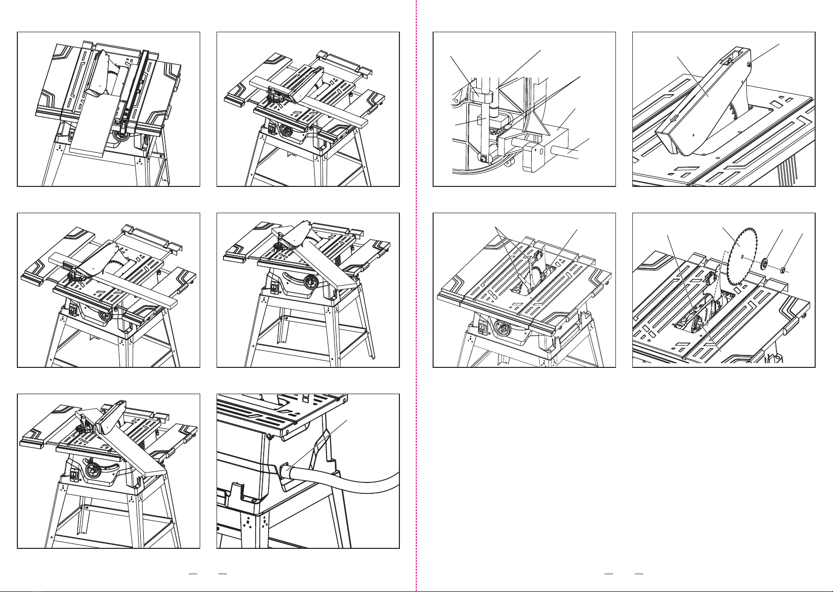
ADJUSTING THE BEVEL STOPS (FIG. 6-1, 6-2 & 6-3)
This saw has positive stops that will quickly position the saw blade
at 90° or 45° to the table.
The angle settings of the saw have been set at the factory and,
unless damaged in shipping, should not require setting during
assembly. After extensive use, it may need to be checked. Make
adjustments only if necessary.
1. Unplug the saw.
2. Raise the blade to the maximum height by turning the high
adjusting handle clockwise.
3. Using a square (37), set the blade to exactly 90°. (Fig. 6-2)
4. If the blade stops bevelling before it gets to 90°, loosen the 90°
stop screw (38) (located in the left of the table insert) (Fig. 6-1)
with the 5 mm hex key (supplied), and then adjust it to 90°.
5. With the blade set at 90°, slowly turn the 90°-stop set screw until
you feel resistance. Bevel the blade away from 90° a little, and
then back to the stop.
6. Re-measure the angle, and repeat the stop adjustment as
necessary until the blade stops at 90°.
7. Set the 45° stop in the same way. The set screw for the 45° stop
(39) is located in the right of table insert.
INSTALLING BATTERY FOR LASER GUIDE (FIG. 7-1 & 7-2)
WARNING: The laser must align with the saw blade.
1. Raise the saw blade (13) to the heightest position.
2. Turning the saw blade to 0° position and lock blade bevel lock
knob (8).
3. Loose the cross-screw (40) with the screwdriver (not supplied).
4. Remove the laser cover (41).
5. Place the batteries (42).
NOTE: Pay attention to correct polarity.
6. Refix the laser cover (41).
7. Tighten the cross-screw (40).
WARNING: Do not operate when the saw is on working.
ADJUSTING LASER GUIDE (FIG. 7-1)
WARNING: The laser must align with the saw blade.
1. Raise the saw blade (13) to the heightest position.
2. Turning the saw blade to 0° position and lock blade bevel lock
knob (8).
3. Loosen the two cross-screws (43).
4. Align the laser (44) to the saw blade.
5. Tighten the two cross-screws (43).
LASER GUIDE
1. A laser beam is not a toy, and it should not be used by children.
Misuse of the laser line can lead to irreparable eye damage.
2. It is strongly advised that you use laser protective eyewear for
the specific wavelength of emitted light when working on or near
reflective surface.
3. Do not perform any adjustments that are intended to increase
the power of the laser.
4. When using the laser line, do not point the laser beam at people
and/or reflecting surface. Even a low-intensity laser beam can
cause eye damage. Do not look directly into the laser beam.
5. If the laser line will not be used for more than three months.
Remove the batteries in order to avoid damage from possible
leakage.
6. The laser line does not include any user-serviceable components.
Do not open the housing in an attempt to repair it.
7. Repairs should only be carried out at a service centre or by an
authorized service technician.
TO ASSEMBLE THE BLADE GUARD (FIG. 8-1 & 8-2)
WARNING: The saw blade guard must be in position at all times
to prevent contact with the blade. It should lift up and onto
the workpiece when the workpiece is passed through the saw.
1. Attach the blade guard (1) over the riving knife (3) so that the
hole in the guard and the hole in the riving knife are aligned.
2. Insert the screw M6 x45 (31) and fit the flat washer 6 (32) and
hex nut M6 (30).
3. Tighten the hex nut (30) sufficiently so that the guard rests on
the table top but will lift when the workpiece is pushed into the
table.
4. Blade guard (1) in place as shown in Fig. 8-2.
WARNING: The blade guard should return to its rest position after
the workpiece has been cut.
CHANGING THE BLADE DEPTH (FIG. 9)
The saw blade depth should be set so that the outer points of the
saw blade are higher than the workpiece by approximately 1/8” (3.2
mm) to 1/4” (6.4 mm), but the lowest points (gullets) (45) are below
the top surface.
1. Unplug the saw.
2. Turn the blade bevel lock knob (8) clockwise to tighten it
securely.
3. Raise the blade (13) by turning the height adjusting handle
clockwise, or lower it by turning the handle counterclockwise.
CHANGING THE BLADE ANGLE (FIG. 10)
1. Unplug the saw.
2. Loosen the blade bevel lock knob (8) by turning it counterclockwise.
3. To adjust the bevel angle, turning the height/bevel adjusting
handwheel (10) counterclockwise increases the angle of the blade,
bringing it closer to 45°; Turning it clockwise decreases the angle,
bringing the blade closer to 90°.
4. To lock by turning the blade bevel lock knob (8) clockwise.
ASSEMBLY THE SIDE EXTENSION TABLE (FIG. 11-1 & 11-2)
1. Sliding the tubes (46) into the two holes at the side of the main
table.
2. Fix the screws M4 x 10 (47) into the holes at the end of both
extension tubes to prevent you from pulling the side table too far
out.
3. You can lock at the desired position with the two locking knobs
(48) at the bottom of the main table.
ASSEMBLY THE REAR EXTENSION TABLE (FIG. 12-1 & 12-2)
1. Sliding the tubes (46) into the two holes at the back of the main
table.
2. Fix the screw M4 x 10 (47) into the hole at the end of extension
tube located near the sliding table to prevent you from pulling the
side table too far out.
3. You can lock at the desired position with the two locking knobs
(48) at the bottom of the main table.
TO ASSEMBLY THE RIP FENCE (FIG. 13)
Lift the rip fence handle (49) until the rear holding clamp (50) is fully
extended.
1. Place the rip fence (4) on the saw table, lowering the rear of the
fence onto the table first.
2. Push down the rip fence handle (49) in order to lock the rip fence
in position.
ADJUSTING THE RIP FENCE INDICATOR (FIG. 14)
1. The rip fence indicator (51) points to the measurement scale (52).
The scale shows the distance from the side of the fence closest
to blade.
2. Measure the actual distance with a ruler. If there is a difference
between the measurement and the indicator, adjust the indicator.
Loosen the screw, and slide the indicator to the correct
measurement on the scale. Tighten the screw, and re-measure
with the ruler.
TO ASSEMBLY THE AUXILIARY RIP FENCE (Fig. 15-1 & 15-2)
When cutting narrow workpieces and for bevel cuts, the auxiliary
rip fence (15) (aluminum) must be mounted to the rip fence (4).
The auxiliary rip fence (15) can be mounted left or right side of the
rip fence (4).
1. Insert the profile rail into the groove on the short side of
the auxiliary rip fence.
2. Position the profile rail in front of the rip fence in such a manner
that the holes of both parts are in alignment.
3. Insert the fastening knobs (53) through the lateral holes in the rip
fence and tighten them.
When sawing high, narrow work pieces, the auxiliary rip fence
(aluminum) must be mounted directly to rip fence.
1. Fasten the auxiliary rip fence with the 2 square nuts (54) (not
supplied) and the fastening knobs directly to the rip fence.
INSTALLING THE MITER GAUGE (Fig. 16-1 & 16-2)
1. Attach the rip fence for miter gauge (55) to the miter gauge by
tighten two locking knobs (56). (Fig. 16-1)
2. Insert the guide rail of the miter gauge into one of the guide
grooves (57) of the saw table intended for this purpose.
ADJUSTING THE MITER GAUGE (Fig. 17-1 & 17-2)
1. Loosen the locking handle (58) in order to allow the miter body
(59) to rotate freely.
Position the miter body at 90° so that the positive detent secures
it in position. Tighten the locking handle in order to hold the miter
body securely in position.
2. If the pointer (60) requires adjustment, loosen the cross-screw
(61) that is located under the pointer using a screwdriver. Adjust
the pointer to 90° on the scale, and then tighten the adjusting
screw firmly.
3. In order to change the angle of the miter gauge, loosen the
locking handle (58) and the rotate the miter body (59) to
the desired angle, as indicated on the scale. Tighten the locking
handle (58) in order to hold the miter body (59) securely
in position.
OPERATION
For safety reasons, verify that the operator has read the section
entitled general safety guidelines for the table saw before operating
this saw. Verify the following before every time the table saw
is used:
• The blade is tight.
• The blade bevel lock knob is locked.
• If ripping, the rip fence locking knob is tight, and the fence
is parallel to the miter gauge groove and the blade.
• If crosscutting, the miter gauge knob is tight.
• The blade guard and splitter are in place, and are working properly.
• Safety glasses are worn.
• Failure to adhere to these safety rules will greatly increase the
chances of injury.
Before using the table saw, polish the tabletop with an automotive
polishing wax in order to keep it clean, and to make it easier to slide
the workpiece.
There are two basic types of table saw cuts: ripping and crosscutting.
Ripping refers to cutting along the length of the grain and the work
piece. Crosscutting refers to either cutting across the width or across
the grain of the work piece. This distinction may be hard to make
with man made materials. Therefore, cutting a piece of material
to a different width is ripping, and cutting across the short dimension
is crosscutting.
Neither operation can be performed safely freehand: ripping requires
the use of the rip fence, and crosscutting requires the use of the
miter gauge. Never use the rip fence and the miter gauge at the
same time during the cutting operation.
ON/OFF SWITCH (Fig. 18)
Switching On
To start the operation, press the green I-push button (62).
Switching Off
Press the red O-push button (63) to stop the saw.
OVERLOAD PROTECTION (Fig. 19)
This saw is equipped with a reset overload relay button. It is situated
at the immediate right of the ON/OFF switch.
The reset button will restart the motor after it shuts off due
to overloading or low voltage.
If the motor stops during operation, press the red O-push button (63)
to make sure the switch is OFF. Wait approximately five minutes
for the motor to cool down and push the reset button. Now you can
switch to the ON position again.
WARNING: In order to avoid injury and prevent accidental start-up
when the reset button is pushed, the switch should be in the off
position, and the power cord should be unplugged from the outlet
while the saw is cooling down. Overheating may be caused by an
under-sized extension cord, an extension cord that is too long,
misaligned parts, or a dull blade. inspect the saw for proper set-up
before using it again.
USING SIDE EXTENSION TABLE (Fig. 11-1 & 11-2)
1. Unlock the side extension table locking knob (48) underneath
the main table.
2. Slide the extension tubes (46) in or out until the scale on the tube
is positioned at the desired distance. Lock the extension table
locking knob (48).
3. To adjust the position of the rip fence, loosen the locking handle
(49), and place the auxiliary rip fence (15) in position by using
the calibration point in red.
4. Tighten the locking handle (49).
USING REAR EXTENSION TABLE (Fig. 12-1 & 12-2)
1. Unlock the rear extension table locking knob (48) underneath
the main table.
2. Slide the extension tubes (46) in or out until the tube is positioned
at the desired distance. Lock the extension table locking knob
(48).
RIPPING (Fig. 20)
1. Remove the miter gauge, and secure the rip fence to the table.
2. Raise the blade until it is approximately 1/8” (3.2 mm) above the
top of the work piece.
3. Place the work piece flat on the table and against the fence so
that the larger portion of the work piece is between the blade and
the fence. Keep the work piece approximately 1” (2.5 cm) away

17 18
from the blade.
4. Turn the saw ON, and wait for the blade to reach full speed.
5. Slowly feed the work piece into the blade by pushing forward on
the section of the work piece that will pass between the blade
and the fence.
6. Do not place your thumbs on the table top. Always hold the work
piece while the blade is turning. Do not let go of it in order to
reach for the push stick. When both thumbs touch the front edge
of the table, complete the cut using a push stick.
7. Always use the push stick when performing ripping operations.
8. Continue to push the work piece with the push stick until it passes
the blade guard and clears the rear of the table.
9. Do not pull the work piece backward while the blade is turning.
Turn the switch OFF, and unplug the power cord. Wait until the
blade comes to a complete stop and slide the work piece out.
BEVEL RIPPING (Fig. 21)
Bevel ripping is the same as ripping, except that the blade bevel
angle is set to an angle other than “0”.
WARNING: The workpiece and the fence must be on the right side
of the blade when cutting.
RIPPING SMALL PIECES
WARNING: Avoid injury caused by contact with the blade. Do not
use this saw to make through-cuts that are narrower than 1/2”
(13 mm).
1. It is not safe to rip small pieces. Instead, rip a larger piece in
order to obtain the size of the desired piece.
2. When ripping a small work piece, it is not safe to place the hand
between the blade and the rip fence. Use one or more push
sticks to push the work piece completely past the blade.
CROSSCUTTING (Fig. 22)
1. Remove the rip fence and place the miter gauge in the miter
gauge groove on the table.
2. Raise the blade until it is approximately 1/8” (3.2 mm) above the
top of the work piece.
3. Hold the work piece firmly against the miter gauge, with the path
of the blade in line with the desired cutting line. Move the work
piece to within 1” (2.5 cm) of the blade.
4. Start the saw, and wait for the blade to reach full speed. Do not
stand directly in line with the saw blade’s path. Instead, stand on
the side where the cut is being made.
5. Keep the work piece against the face of the miter gauge and flat
against the table. Slowly push the work piece through the blade.
6. Do not attempt to pull the work piece backward while the blade
is turning. Turn the switch OFF, and wait until the blade
has come to a complete stop before carefully sliding the work
piece.
WARNING: In order to avoid instability, always place the larger
surface of the workpiece on the table when crosscutting and/
or bevel crosscutting.
BEVEL CROSSCUTTING 0°-45° BLADE BEVEL & 90° MITER
ANGLE (Fig. 23)
This operation is the same as crosscutting, except that the blade is
at a bevel angle other than 0°.
1. Adjust the blade to the desired angle, and then tighten the blade
bevel locking knob.
2. Tighten the miter locking handle at 90°.
3. Hold the work piece firmly against the face of the miter gauge
throughout the cutting operation.
COMPOUND MITER CROSSCUTTING 0°~45° BLADE BEVEL
& 0°-45° MITER ANGLE (Fig. 24)
This sawing operation combines a miter angle with a bevel angle.
1. Set the miter gauge to the desired angle.
2. Set the blade bevel to the desired bevel angle, and tighten the
blade bevel locking knob.
3. Hold the work piece firmly against the face of the miter gauge
throughout the cutting operation.
MITERING: 0°-45° MITER ANGLE (Fig. 25)
This operation is the same as crosscutting, except that the miter
gauge is locked at an angle other than 90°.
1. Set the blade to a 0° bevel angle, and tighten the blade bevel
locking knob.
2. Set the miter gauge to the desired miter angle, and secure it in
position by tightening the miter gauge locking handle.
3. Hold the work piece firmly against the face of the miter gauge
throughout the cutting operation.
TO USE DUST EXTRACTION PORT (Fig. 26)
WARNING: To prevent fire hazard, clean and remove sawdust from
under the saw frequently.
1. To prevent sawdust buildup inside the saw housing, for best
result, attach a vacumm hose (not included) to the dust extraction
port (64). DO NOT operate the saw with hose in place unless the
vacuum is turned on.
2. If the saw is operated without a vacuum attached, some of the
dust will be blown out the dust extraction port (64). After extended
use, the saw’s dust collection system may become clogged.
MAINTENANCE
CAUTION! For your own safety, turn the switch OFF. Remove the
plug from the power source before maintaining or lubricating your
saw.
GENERAL MAINTENANCE
Clean out all sawdust that has accumulated inside the saw base
and around the motor. Polis the saw table with an automotive wax
in order to keep it clean and to make it easier to slide the workpiece.
Clean the cutting blades with pitch and gum remover. Immediately
replace a worn, cut, or damaged power cord.
CAUTION! All electrical and mechanical repairs should be performed
by a qualified repair technician. Use only identical replacement parts.
Any substitute parts may create a hazard.
Use liquid dish washing detergent and water to clean all plastic parts.
NOTE: The use of certain cleaning chemicals may damage solvents
on your table saw: gasoline, carbon tetrachloride, chlorinated solvents,
ammonia, and household detergents that contain ammonia.
BLADE RAISING MECHANISM (Fig. 27)
The blade raising mechanisms should be checked for looseness,
binding, or other abnormalities after every five hours of operation.
Disconnect the table saw from the power source and turn it upside
down, and then alternately pull upward and downward on the motor
unit. Observe any movement in the motor mounting mechanism.
1. Turn the screw pole in the fixed part connection with the wheel.
2. The power will be transferred by the taper gear and screw pole.
3. The pole in the fixed part will be move up and down.
Place a small amount of dry lubricant, such as graphite or silicone,
on the screw rod at the thrust washer. Do not oil the threads of the
screw rod. For smooth operation, the screw rod must be kept clean
and free of sawdust, gum, pitch, and other contaminants. Wet
lubricants such as oil will attract sawdust etc. If excessive looseness
is observed in any other part of the blade raising or tilting mechanisms,
contact your dealer or RYOBI service centre.
All motor bearing are permanently lubricated at the factory, and
do not require any additional lubrication. Lubricate all mechanical
parts of your table saw where a pivot or threaded rod is present with
graphite or silicone. These dry lubricicants will not hold sawdust
like oil or grease will.
TO REPLACE THE BLADE (Fig. 28-1, 28-2 & 28-3)
When you need replace the saw blade, please follow the procedure
as belowing:
1. Unplug the saw.
2. Loosen the hex nut (30) and remove the blade guard (1).
(Fig. 28-1)
3. Turn height adjustment hand wheel (10) counterclockwise to
drop the saw blade to lowest position. Loosen the six cross-
screws (29) and remove the table insert (2).
4. Turn hand wheel clockwise to raise blade to maximum height.
5. Using one opened-ended blade wrench (65), place the flat open
end on the flats on the outer blade flange (66).
6. Using the other opened-ended blade wrench (65), place the flat
open end on the flats on the arbor nut (67). Holding both wrenches
firmly, pull the opened-ended blade wrench on the arbor nut
(67) forward to the front of the machine.
WARNING: Arbor shaft has left-hand threads. Be extremely careful
when loosening arbor nut. Keep firm grasp on both wrenches. Do
not allow hands to slip and contact blade.
7. Remove arbor nut (67), outer blade flange (66) and saw blade
(13).
8. Place one new blade on arbor(68). Make sure saw blade teeth
point down at the front side of saw table. Place outer flange (66)
and nut (67) on arbor (68) and use blade wrenches (65) to tighten
nut (67) securely. Arbor and blade securely snug in position.
9. Lower the saw blade (13) to lowest position and replace table
insert (2).
10. Replace blade guard (1).
WARNING: Verify that the saw blade (13), the arbor flange, and the
nut (67) are properly seated, and that the arbor nut (67) is tightened
securely.

Table of contents
Other Ryobi Saw manuals

Ryobi
Ryobi BT3100-1 User manual

Ryobi
Ryobi SC164VS User guide

Ryobi
Ryobi P2503 User manual

Ryobi
Ryobi TS1342LBF User manual

Ryobi
Ryobi RTBS18X User manual

Ryobi
Ryobi RTS21 User manual

Ryobi
Ryobi EMS2431SCL Instructions for use

Ryobi
Ryobi RY43160A User manual

Ryobi
Ryobi RTS08T User manual

Ryobi
Ryobi RTS22 User manual
Popular Saw manuals by other brands

Makita
Makita N5900B instruction manual

Toolex
Toolex 535819 instruction manual

wurth
wurth KTS 140 Combi Translation of the original operating instructions

Makita
Makita LS1030N instruction manual

Scheppach
Scheppach CRS450-20ProS Translation of original instruction manual

RIDGID
RIDGID MS 1290 owner's manual