Ryobi RY15523 User manual

L’accessoire taille-bordures a été conçue et fabriquée conformément
à nos strictes normes de fiabilité, simplicité d’emploi et sécurité
d’utilisation. Correctement entretenue, elle vous donnera des
années de fonctionnement robuste et sans problème.
AVERTISSEMENT : Pour réduire les risques de
blessures, l’utilisateur doit lire et veiller à bien comprendre le
manuel d’utilisation avant d’employer ce produit.
Merci de votre achat.
Su nuevo accesorio para recortar ha sido diseñada y fabricada
de conformidad con las estrictas normas para brindar fiabilidad,
facilidad de uso y seguridad para el operador. Con el debido cuidado,
le brindará muchos años de sólido y eficiente funcionamiento.
ADVERTENCIA: Para reducir el riesgo de lesiones,
el usuario debe leer y comprender el manual del operador antes
de usar este producto.
Le agradecemos su compra.
OPERATOR’S MANUAL
MANUEL D’UTILISATION
MANUAL DEL OPERADOR
STRAIGHT SHAFT
TRIMMER ATTACHMENT
ARBRE DROIT ACCESSOIRE
TAILLE-BORDURES
ACCESORIO PARA RECORTAR
DE EJE RECTO
RY15523
CONSERVER CE MANUEL POUR
FUTURE RÉFÉRENCE
GUARDE ESTE MANUAL PARA
FUTURAS CONSULTAS
SAVE THIS MANUAL FOR FUTURE REFERENCE
Your trimmer attachment has been engineered and manufactured to our high standard for dependability, ease of operation,
and operator safety. When properly cared for, it will give you years of rugged, trouble-free performance.
WARNING: To reduce the risk of injury, the user must read and understand the operator’s manual before using
this product.
Thank you for your purchase.

ii
Fig. 1
E
B
C
A
A - Hanger cap (capuchon de suspension, tapa
de suspensión)
B - Trimmer shaft (arbre du taille-bordures, eje
de la recortadora)
C - Gear head (carter d’engrenages, cabezal de
engranajes)
Fig. 3 A
DB
C
Fig. 2
B
G
E
A
F
C
D
A - Wing screw (vis à oreilles, tornillo de
mariposa)
B - Tab (languette, orejeta)
C - Slot (fente, ranura)
D - Grass deflector (déflecteur d’herbe,
deflector de pasto)
A - Power head shaft (arbre moteur, cabezal
motor eje)
B - Coupler (coupleur, acoplador)
C - Guide recess (renfoncement du guide,
hueco guía)
D - Button (bouton, botón)
E - Attachment shaft (arbre de l’accessoire, eje
del accesorio)
F - Positioning hole (trou de positionnement,
orificio de posicionamiento)
G - Knob (bouton, perilla)
Fig. 4
A
A - Line trimming cut-off blade (lame de
sectionnement de ligne, cuchilla de corte)
See this fold-out section for all of the figures referenced in the operator’s manual.
Consulter l’encart à volets afin d’examiner toutes les figures mentionnées dans le manuel d’utilisation.
Consulte esta sección desplegable para ver todas las figuras a las que se hace referencia en el manual del operador.
PROPER OPERATING POSITION / BONNE
POSITION DE TRAVAIL / POSICIÓN
CORRECTA PARA EL MANEJO DE LA
HERRAMIENTA
Fig.5
D - String head (tête à ligne de coupe, cabezal
del hilo)
E - Grass deflector (déflecteur d’herbe,
deflector de pasto)
D
C
A
B
A - Dangerous cutting area (zone de coupe
dangereuse, área peligrosa de corte)
B - Direction of rotation (sens de rotation,
sentido de rotación)
C - Best cutting area (zone d’efficacité
maximum, mejor área de corte)
Fig. 6

iii
Fig. 11
A - Drive shaft (arbre moteur, eje de impulsión)
B - string head (tête de coupe, cabezal del hilo)
C - Spool retainer (retenue de bobine, retén del
carrete)
C
B
A
Fig. 7 Fig. 10
A - Eyelet (oeillet, ojillo)
B - Arrow on spool (flèche sur la bobine, flecha
en el carrete)
A
B
Fig. 8
A
A - Spool retainer (retenue de bobine, retén del
carrete)
Fig. 9 A
B
A - Spool retainer (retenue de bobine, retén del
carrete)
B - Spool (bobine, carrete)
A - Pull strings (tirer vers l’extérieur, tira del
hilo)
B - Rotate the spool counterclock wise (tourner
le bobine dans le sens antihoraire, gire a la
izquierda el carrete)
A
A
A - Pull strings (tirer vers l’extérieur, tira del
hilo)
Fig. 12
A - Hole (trou, orificio)
B - Secondary hole (trou secondaire, orificio
secundario)
C - Button (bouton, botón)
D - Hanger cap (capuchon de suspension, tapa
de suspensión)
C
A
D
B
Fig. 13

2
Introduction ...................................................................................................................................................................... 2
Introduction / Introducción
General Safety Rules........................................................................................................................................................ 3
Règles de sécurité générales / Reglas de seguridad generales
Specific Safety Rules........................................................................................................................................................ 3
Règles de sécurité particulières / Reglas de seguridad específicas
Symbols............................................................................................................................................................................ 4
Symboles / Símbolos
Features............................................................................................................................................................................ 5
Caractéristiques / Características
Assembly.......................................................................................................................................................................5-6
Assemblage / Armado
Operation.......................................................................................................................................................................6-7
Utilisation / Funcionamiento
Maintenance..................................................................................................................................................................8-9
Entretien / Mantenimiento
Warranty ......................................................................................................................................................................... 10
Garantie / Garantía
Exploded View and Parts List....................................................................................................................................11-12
Vue éclatée et liste des pièces / Vista desarrollada y lista de piezas
Parts Ordering and Service ...............................................................................................................................Back Page
Commande de pièces et réparation / Pedidos de piezas y servicio ......................................................... Page arrière / Pág. posterior
TABLE OF CONTENTS
TABLE DES MATIÈRES / ÍNDICE DE CONTENIDO
INTRODUCTION
INTRODUCTION / INTRODUCCIÓN
This product has many features for making its use more pleasant and enjoyable. Safety, performance, and dependability
have been given top priority in the design of this product making it easy to maintain and operate.
* * *
Ce produit offre de nombreuses fonctions destinées à rendre son utilisation plus plaisante et satisfaisante. Lors de la
conception de ce produit, l’accent a été mis sur la sécurité, les performances et la fiabilité, afin d’en faire un outil facile à
utiliser et à entretenir.
* * *
Este producto ofrece numerosas características para hacer más agradable y placentero su uso. En el diseño de este producto
se ha conferido prioridad a la seguridad, el desempeño y la fiabilidad, por lo cual se facilita su manejo y mantenimiento.

3 — English
WARNING:
Read and understand all instructions. Failure to follow
all instructions listed below may result in electric shock,
fire, and/or serious personal injury.
SAVE THESE INSTRUCTIONS
Readthese instructionsand theinstructions forthe power
head thoroughly before using the straight shaft trimmer
attachment.
Know the tool. Read and understand the operator’s
manual and observe the warnings and instruction labels
affixed to the tool.
Do not allow children or untrained individuals to use this
unit.
Always wear eye protection with side shields marked to
comply with ANSI Z87.1.
Wear heavy long pants, boots, and gloves. Do not wear
loose fitting clothing, short pants, jewelry of any kind, or
go barefoot.
Secure long hair so it is above shoulder level to prevent
entanglement in any moving parts.
Keep all bystanders, children, and pets at least 50 ft.
away. Bystanders should be encouraged to wear eye
protection.
Stay alert, watch what you are doing, and use common
sense when operating a power tool. Do not use tool while
tired or under the influence of drugs, alcohol, or medica-
GENERAL SAFETY RULES
tion. A moment of inattention while operating power tools
may result in serious personal injury.
Do not operate in poor lighting.
Do not overreach. Keep proper footing and balance at all
times. Proper footing and balance enables better control
of the tool in unexpected situations.
Keep all parts of your body away from any moving part.
Do not touch areas around the muffler or cylinder of the
power head. These parts get hot from operation. Failure
to heed this warning could result in possible serious
personal injury.
Always stop the engine and remove the spark plug wire
before making any adjustments or repairs except for
carburetor adjustments.
Inspect unit before each use for loose fasteners and dam-
aged or missing parts. Correct before using the trimmer
attachment. Failure to do so can cause serious injury.
Use only original manufacturer’s replacement parts.
Failure to do so may cause poor performance, possible
injury, and will void your warranty.
Do not, under any circumstance, use any attachment or
accessory on this product, which was not provided with
the product, or identified as appropriate for use with this
product in the operator’s manual.
Avoid dangerous environments. Do not use the attach-
ment in damp or wet locations. Do not use in rain.
Use the right attachment. Do not use attachment for any
job except that for which it is intended.
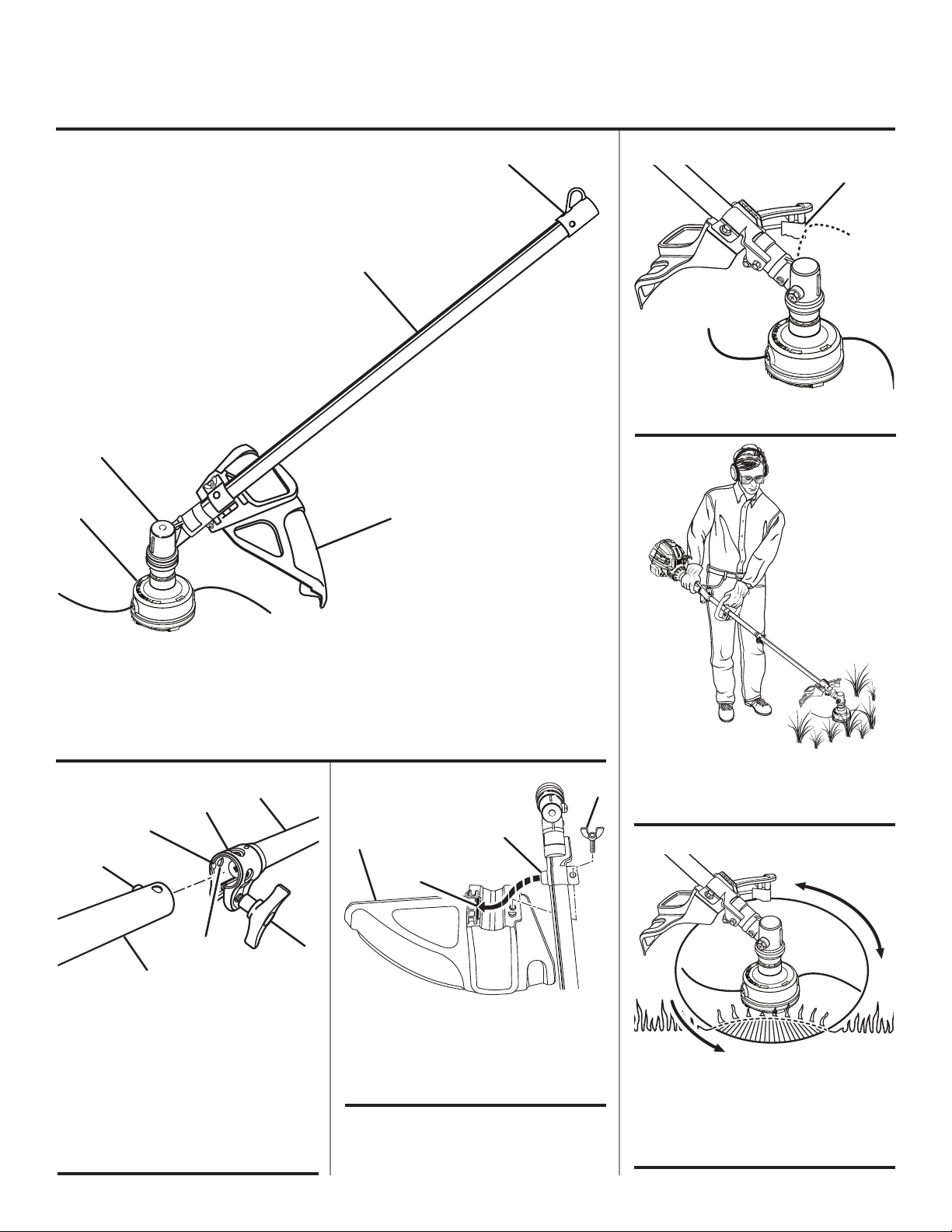
Replace string head if cracked, chipped, or damaged
in any way. Be sure the string head is properly installed
and securely fastened. Failure to do so can cause serious
injury.
Make sure all deflectors and handles are properly and
securely attached.
Use only flexible, non-metallic line recommended by the
manufacturer. Never use wire, wire rope, or flail blades,
which can break off and become dangerous projec-
tiles.
Never operate string trimmer without the grass deflector
in place and in good condition.
Maintain a firm grip on both handles while trimming.
SPECIFIC SAFETY RULES
Keep string head below waist level. Never cut with
the string head located over 30 in. or more above the
ground.
Clear the work area before each use. Remove all objects
such as rocks, broken glass, nails, wire, or string which
can be thrown or become entangled in the cutting line.
To prevent electrical shock or serious personal injury, do
not use this product with any electric power head.
Save these instructions. Refer to them frequently and
use them to instruct others who may use this tool.
If you loan someone this tool, loan them these in-
structions also to prevent misuse of the product and
possible injury.
NOTE: SEE YOUR POWER HEAD OPERATOR’S MANUAL
FOR ADDITIONAL SPECIFIC SAFETY RULES.

4 — English
SYMBOLS
Some of the following symbols may be used on this product. Please study them and learn their meaning. Proper
interpretation of these symbols will allow you to operate the product better and safer.
SYMBOL NAME EXPLANATION
Safety Alert Symbol Indicates a potential personal injury hazard.
Read the Operator’s Manual To reduce the risk of injury, user must read and understand
operator’s manual before using this product.
Eye and Hearing Protection
Always wear eye protection with side shields marked to
comply with ANSI Z87.1, along with hearing protection when
operating this equipment.
Keep Bystanders Away Keep all bystanders at least 50 ft. away.
Ricochet Thrown objects can ricochet and result in personal injury or
property damage.
No Blade Do not install or use any type of blade on a product
displaying this symbol.
The following signal words and meanings are intended to explain the levels of risk associated with this product.
SYMBOL SIGNAL MEANING
DANGER: Indicates an imminently hazardous situation, which, if not avoided, will result
in death or serious injury.
WARNING: Indicates a potentially hazardous situation, which, if not avoided, could result
in death or serious injury.
CAUTION: Indicates a potentially hazardous situation, which, if not avoided, may result in
minor or moderate injury.
CAUTION: (Without Safety Alert Symbol) Indicates a situation that may result in property
damage.

5 — English
FEATURES
KNOW YOUR STRING TRIMMER
ATTACHMENT
See Figure 1.
The safe use of this product requires an understanding of
the information on the product and in this operator’s manual
as well as a knowledge of the project you are attempting.
Before use of this product, familiarize yourself with all op-
erating features and safety rules.
GRASS DEFLECTOR
The trimmer includes a grass deflector that helps protect
you from flying debris.
ASSEMBLY
UNPACKING
This product requires assembly.
Carefully remove the items from the box. Make sure that
all items listed in the packing list are included.
WARNING:
Do not use this product if any parts on the packing list
are already assembled to your product when you unpack
it. Parts on this list are not assembled to the product by
the manufacturer and require customer installation. Use
of a product that may have been improperly assembled
could result in serious personal injury.
Inspect the unit carefully to make sure no damage oc-
curred during shipping.
Do not discard the packing material until you have
carefully inspected and satisfactorily operated the
product.
If any parts are damaged or missing, please call
1-800-860-4050 for assistance.
PACKING LIST
Ryobi®Expand-it™Straight Shaft Trimmer Attachment
Grass Deflector
Operator’s Manual
WARNING:
If any parts are damaged or missing do not operate this
product until the parts are replaced. Use of this product
with damaged or missing parts could result in serious
personal injury.
WARNING:
Do not attempt to modify this product or create acces-
sories not recommended for use with this product. Any
such alteration or modification is misuse and could result
in a hazardous condition leading to possible serious
personal injury.
WARNING:
Donot connectto powerhead untilassembly iscomplete.
Failure to comply could result in accidental starting and
possible serious personal injury.
JOINING THE POWER HEAD TO THE
STRAIGHT SHAFT TRIMMER ATTACHMENT
See Figure 2.
WARNING:
Never attach or adjust any attachment while power head
is running. Failure to stop the engine or motor may cause
serious personal injury.
PRODUCT SPECIFICATIONS
Weight ................................................................... 3.25 lbs.
Line Cutting Width...................................................... 18 in.
Line Diameter
Gas Power Head ................. .080 in. to .095 in. max.
Electric Power Head.................................. .080 max.

6 — English
WARNING:
Do not allow familiarity with this product to make you
careless.Rememberthat acarelessfraction ofa secondis
sufficient to inflict serious injury.
WARNING:
Always wear eye protection with side shields marked to
comply with ANSI Z87.1. Failure to do so could result in
objects being thrown into your eyes, resulting in possible
serious injury.
WARNING:
Do not use any attachments or accessories not
recommended by the manufacturer of this product. The
use of attachments or accessories not recommended
can result in serious personal injury.
ASSEMBLY
OPERATION
APPLICATIONS
You may use this product for the purpose listed below:
Trimming grass and weeds from around porches, fences,
and decks
LINE TRIMMING CUT-OFF BLADE
See Figure 4.
The trimmer is equipped with a line trimming cut-off blade
on the grass deflector. Replace the line whenever you hear
the engine running faster than normal, or when trimming
efficiency diminishes. This will maintain best performance.
OPERATING THE TRIMMER
See Figure 5.
WARNING:
Engine housing on gas power heads may become hot
during trimmer operation. Do not rest or place your arm,
hand, or any body part against the engine housing dur-
ing trimmer operation. Only hold the trimmer as shown
in Figure 4 with all body parts clear of engine housing.
Extended contact with the engine housing may result in
burns or other injuries.
The straight shaft trimmer attachment connects to the power
head by means of a coupler device.
Remove the hanger cap from the attachment shaft.
Loosen the knob on the coupler of the power head shaft.
Push in the button located on the straight shaft trimmer
attachment. Align the button with the guide recess on the
power head coupler and slide the two shafts together.
Rotate attachment shaft until button locks into the posi-
tioning hole.
NOTE: If the buttons do not release completely in the
positioning holes, the shafts are not locked into place.
Slightly rotate from side to side until the button is locked
into place.
Tighten the knob securely.
WARNING:
Be certain the knob is fully tightened before operating
equipment. Check it periodically for tightness during use
to avoid serious injury.
ATTACHING THE GRASS DEFLECTOR
See Figure 3.
NOTE: Install the grass deflector before the attachment is
connected to the power head.
Remove the wing screw from the grass deflector.
Insert the tab on the mounting bracket in the slot on the
grass deflector.
Align the screw hole in the mounting bracket with the
screw hole in the grass deflector.
Insert the wing screw through the mounting bracket and
into the grass deflector.
Tighten the screw securely.
REMOVING THE ATTACHMENT FROM THE
POWER HEAD
For removing or changing the attachment:
Stop the engine or motor.
Loosen the knob.
Push in the button and twist the shafts to remove and
separate ends.

7 — English
WARNING:
Always position the unit on the operator’s right side. The
use of the unit on the operator’s left side will expose
the user to hot surfaces and can result in possible burn
injury.
WARNING:
To avoid burns from hot surfaces, never operate unit with
the bottom of the engine above waist level.
Hold the trimmer with your right hand on the rear handle
and your left hand on the front handle. Keep a firm grip with
both hands while in operation. Trimmer should be held at a
comfortable position with the rear handle about hip height.
Always operate trimmer at full throttle for gas power heads
or with the switch trigger fully pressed for electric power
heads. Cut tall grass from the top down. This will prevent
grass from wrapping around the shaft housing and string
head which may cause damage from overheating. If grass
becomes wrapped around the string head, STOP THE EN-
GINE or MOTOR, disconnect the spark plug wire for gas
power heads or disconnect the plug from the power source
for electric power heads, and remove the grass. Prolonged
cutting at partial throttle will result in lubricant dripping from
the muffler.
WARNING:
Always hold the string trimmer away from the body keep-
ing clearance between the body and the product. Any
contact with the housing or string trimmer cutting head
can result in burns and/or other serious personal injury.
OPERATION
CUTTING TIPS
See Figures 5 - 6.
Avoid hot surfaces by always keeping the tool away from
your body. (Proper operating position shown in figure 5.)
Keep the trimmer tilted toward the area being cut; this is
the best cutting area.
The trimmer cuts when passing the unit from right to left.
This will avoid throwing debris at the operator. Avoid cut-
ting in the dangerous area shown in figure 6.
Use the tip of line to do the cutting; do not force string
head into uncut grass.
Wire and picket fences cause extra line wear and break-
age. Stone and brick walls, curbs, and wood may wear
line rapidly.
Avoid trees and shrubs. Tree bark, wood moldings, siding,
and fence posts can easily be damaged by the line.
ADVANCING LINE USING THE REEL-EASY™
TAP ADVANCE SYSTEM
Line advance is controlled by tapping the string head’s
spool retainer on grass while running engine at full throt-
tle for gas power heads or with the switch trigger fully
pressed for electric power heads.
Run engine at full throttle for gas power heads or with the
switch trigger fully pressed for electric power heads.
Tap string head on ground to advance line. Line advances
each time the head is tapped.
Several taps may be required until line strikes the cut off
blade.
Resume trimming.
NOTE: If the line is worn too short you may not be able
to advance the line by tapping it on the ground. If so,
STOP THE ENGINE or MOTOR, disconnect the spark plug
wire for gas power heads or disconnect the plug from
the power source for electric power heads, and manually
advance the line.
ADVANCING THE LINE MANUALLY
Stop the unit. Push the spool retainer down while pulling
on line(s) to manually advance the line.

8 — English
MAINTENANCE
WARNING:
When servicing, use only identical replacement parts.
Use of any other parts may create a hazard or cause
product damage.
WARNING:
Always wear eye protection with side shields marked to
comply with ANSI Z87.1. Failure to do so could result in
objects being thrown into your eyes, resulting in possible
serious injury.
WARNING:
Before inspecting, cleaning, or servicing the machine,
shut off engine, wait for all moving parts to stop, and
disconnect spark plug wire and move it away from spark
plug. Failure to follow these instructions can result in
serious personal injury or property damage.
GENERAL MAINTENANCE
Avoid using solvents when cleaning plastic parts. Most
plastics are susceptible to damage from various types of
commercial solvents and may be damaged by their use. Use
clean cloths to remove dirt, dust, oil, grease, etc.
WARNING:
Do not at any time let brake fluids, gasoline, petroleum-
based products, penetrating oils, etc., come in contact
with plastic parts. Chemicals can damage, weaken or de-
stroy plastic which may result in serious personal injury.
You can often make adjustments and repairs described
here. For other repairs, have the trimmer serviced by an
authorized service dealer.
SPOOL REPLACEMENT
REEL-EASY™TAP ADVANCE SYSTEM
See Figures 7 - 10.
If replacing line only, refer to LINE REPLACEMENT later in
this manual.
Use only .095 in. trimmer line.
Stop the unit and disconnect the spark plug wire. Hold
the string head and unscrew the spool retainer.
Remove the empty spool from the string head.
NOTE: It is not necessary to remove the string head
housing from the drive shaft.
Insert the new spool into the string head.
NOTE: Make sure the arrows on the spool are aligned
with the eyelets in the string head housing. Push down
and hold the spool and housing together while completing
the installation.
Reinstall the spool retainer to secure.
Install line as described in LINE REPLACEMENT.
LINE REPLACEMENT
See Figure 11 - 12.
Stop the unit
Rotate the spool clockwise as necessary to align the
arrows on the spool with the eyelets in the string head
housing.
Cut one piece of trimmer line 10 ft. long. Insert the line
into the eyelet on the string trimmer housing. Push until
the end of the line comes out the other side of the string
head. Pull the line from the other side until equal amounts
of line appear on both sides of the spool.
Rotate the spool clockwise to wind the line on the spool
until approximately 6 in. of line is showing on each side.
Push the spool retainer down while pulling on line(s) to
manually advance the line and to check for proper as-
sembly of the string head.
ATTACHING THE STORAGE HANGER
See Figure 13.
There are two ways to hang the attachment for storage.
Tousethehangercap,pushinthe buttonandplacethehang-
er cap over the end of the attachment shaft. Slightly rotate
the cap from side to side until the button locks into place.
The secondary hole in the attachment shaft can be used
for hanging purposes as well.
STORING THE ATTACHMENT
Store the attachment in a well-ventilated place that is
inaccessible to children.
Keep away from corrosive agents such as garden chemi-
cals and deicing salts.

9 — English
MAINTENANCE
MAKE THE MOST OF YOUR PURCHASE!
Go to www.ryobitools.com and register your new tool on-line.
Your product has been fully tested prior to shipment
to ensure your complete satisfaction.
For any questions about operating or maintaining
your product, call the Ryobi Help Line!
To register your Ryobi product by regular mail, please print the following information on a 3 in. x 5 in. card or
standard postcard: your name, mailing address, phone numbers, email address, Ryobi product(s) purchased
with item number from package, and serial number for each product. Mail the card to: Techtronic Industries
North America, Inc., Attn. Ryobi Registration, 1428 Pearman Dairy Road, Anderson, SC 29625.To receive infor-
mation on our company and products, please include the following statement on your registration card: “Send
me information on your products and company using the contact information I am providing with this product
registration.”

10 — English
WARRANTY
LIMITED WARRANTY STATEMENT
Techtronic Industries North America, Inc., warrants to the
original retail purchaser that this RYOBI®brand outdoor
product is free from defect in material and workmanship
and agrees to repair or replace, at Techtronic Industries
North America, Inc.’s, discretion, any defective product
free of charge within these time periods from the date of
purchase.
Three years if the product is used for personal, family
or household use;
90 days, if used for any other purpose, such as
commercial or rental.
This warranty extends to the original retail purchaser
only and commences on the date of the original retail
purchase.
Any part of this product found in the reasonable judgment
of Techtronic Industries North America, Inc. to be defective
in material or workmanship will be repaired or replaced
without charge for parts and labor by an authorized service
center for RYOBI®brand outdoor products (Authorized
Ryobi Service Center).
Theproduct,including anydefectivepart, mustbe returned
to an authorized Ryobi service center within the warranty
period.The expenseof deliveringthe product tothe service
center for warranty work and the expense of returning it
back to the owner after repair or replacement will be paid
by the owner. Techtronic Industries North America, Inc.’s,
responsibility in respect to claims is limited to making the
required repairs or replacements and no claim of breach of
warranty shall be cause for cancellation or rescission of the
contractof saleofanyRYOBI®brandoutdoorproduct.Proof
of purchase will be required by the dealer to substantiate
any warranty claim. All warranty work must be performed
by an authorized service dealer.
This warranty is limited to ninety (90) days from the date
of original retail purchase for any RYOBI®brand outdoor
product that is used for rental or commercial purposes, or
any other income-producing purpose.
This warranty does not cover any product that has been
subject to misuse, neglect, negligence, or accident, or that
has been operated in any way contrary to the operating
instructions as specified in this operator’s manual. This
warranty does not apply to any damage to the product that
is the result of improper maintenance or to any product
that has been altered or modified. The warranty does not
extend to repairs made necessary by normal wear or by the
use of parts or accessories which are either incompatible
with the RYOBI®brand outdoor product or adversely affect
its operation, performance, or durability. In addition, this
warranty does not cover:
A. Tune-ups – Spark Plugs, Carburetor, Carburetor
Adjustments, Ignition, Filters
B. Wear items – Bump Knobs, Outer Spools, Cutting
Lines, Inner Reels, Starter Pulleys, Starter Ropes, Drive
Belts, Tines, Felt Washers, Hitch Pins, Mulching Blades,
Blower Fans, Blower and Vacuum Tubes, Vacuum Bag
and Straps, Guide Bars, Saw Chains
Techtronic Industries North America, Inc., reserves the
right to change or improve the design of any RYOBI®brand
outdoorproductwithout assumingany obligation tomodify
any product previously manufactured.
ALL IMPLIED WARRANTIES ARE LIMITED IN DURATION
TO THE STATED WARRANTY PERIOD. ACCORDINGLY,
ANY SUCH IMPLIED WARRANTIES INCLUDING
MERCHANTABILITY, FITNESS FOR A PARTICULAR
PURPOSE, OR OTHERWISE, ARE DISCLAIMED
IN THEIR ENTIRETY AFTER THE EXPIRATION OF
THE APPROPRIATE THREE-YEAR OR NINETY-DAY
WARRANTY PERIOD. TECHTRONIC INDUSTRIES
NORTH AMERICA, INC.’S, OBLIGATION UNDER THIS
WARRANTYISSTRICTLYANDEXCLUSIVELYLIMITED TO
THE REPAIR OR REPLACEMENT OF DEFECTIVE PARTS
AND TECHTRONIC INDUSTRIES NORTH AMERICA,
INC., DOES NOT ASSUME OR AUTHORIZE ANYONE
TO ASSUME FOR THEM ANY OTHER OBLIGATION.
SOME STATES DO NOT ALLOW LIMITATIONS ON HOW
LONG AN IMPLIED WARRANTY LASTS, SO THE ABOVE
LIMITATION MAY NOT APPLY TO YOU. TECHTRONIC
INDUSTRIES NORTH AMERICA, INC., ASSUMES NO
RESPONSIBILITY FOR INCIDENTAL, CONSEQUENTIAL,
OR OTHER DAMAGES INCLUDING, BUT NOT LIMITED
TO, EXPENSE OF RETURNING THE PRODUCT TO AN
AUTHORIZED RYOBI SERVICE CENTER AND EXPENSE
OF DELIVERING IT BACK TO THE OWNER, MECHANIC’S
TRAVEL TIME, TELEPHONE OR TELEGRAM CHARGES,
RENTAL OF A LIKE PRODUCT DURING THE TIME
WARRANTY SERVICE IS BEING PERFORMED, TRAVEL,
LOSS OR DAMAGE TO PERSONAL PROPERTY, LOSS
OF REVENUE, LOSS OF USE OF THE PRODUCT, LOSS
OF TIME, OR INCONVENIENCE. SOME STATES DO NOT
ALLOWTHEEXCLUSION ORLIMITATIONOFINCIDENTAL
OR CONSEQUENTIAL DAMAGES, SO THE ABOVE
LIMITATION OR EXCLUSION MAY NOT APPLY TO YOU.
This warranty gives you specific legal rights, and you may
also have other rights which vary from state to state.
This warranty applies toall RYOBI®brand outdoor products
manufacturedbyorfor TechtronicIndustriesNorth America,
Inc., and sold in the United States and Canada.
To locate your nearest Authorized Ryobi Service Center,
dial 1-800-860-4050.

11
18
17
16
15
14
10
9
8
11
12
6
5
4
73
2
1
13
EXPLODED VIEW AND PARTS LIST
VUE ÉCLATÉE ET LISTE DES PIÈCES
VISTA DESARROLLADA Y LISTA DE PIEZAS

12
* STANDARD HARDWARE ITEM — MAY BE PURCHASED LOCALLY
* ARTICLE DE QUINCAILLERIE STANDARD — EN VENTE DANS LES MAGASINS LOCAUX
* ARTÍCULO ESTÁNDAR DE FERRETERÍA — PUEDE ADQUIRIRSE EN LA LOCALIDAD
KEY NO.
Pièce
Num.
Núm. Ref.
PART NO.
Num. Réf.
Núm. Pieza DESCRIPTION DESCRIPTION DESCRIPCIÓN QTY.
Qté.
Cant.
1 940726013 Expand-it Label Autocollant Expand-it Etiqueta Expand-it 1
2 940230132 Warning Decal Autocollant d’avertissement Calcomanía de advertencia 1
3 308035011 Straight Shaft Assembly Arbre droit Conjunto del eje recto 1
4 660736001 * Screw (10-24 x 5/8 in.) Vis (10-24 x 5/8 po) Tornillo (10-24 x 5/8 pulg.) 1
5 638125001 Clamp Bride Abrazadera 1
6 518367001 Spacer Pièce d’écartement Separador 1
7 660642001 Screw (1/4-20 x 1-1/4 in.) Vis (1/4-20 x 1-1/4 po) Tornillo (1/4-20 x 1-1/4 pulg.) 1
8 308210002 Gear Head Carter d’engrenages Cabezal de engranajes 1
9 678011002 Flanged Washer Rondelle à épaulement Arandela de brida 1
10 678019002 Arbor Axe Árbol 1
11 660886001 Wing Screw (1/4-20 x 1-1/4 in.) Vis à oreilles (1/4-20 x 1-1/4 po) Tornillo de mariposa (1/4-20 x
1-1/4 pulg.) 1
12 308473001 Grass Deflector Assembly
(Incl. Key No. 11)
Déflecteur d’herbe (incl. pièce
no. 11)
Conjunto del deflector de pasto
(incl. pzas núm. ref. 11) 1
13 518019002 Hanger Cap Capuchon de suspension Tapa de suspensión 1
14 310643001 Bump Feed String Head Tête de coupe à alimentation par
choc
Cabezal del hilo con alimentación
por golpe 1
15 678022001 Spring Ressort Resorte 1
16 310412001 Bump Feed Spool Bobine à alimentation par choc Carrete con alimentación por golpe 1
17 308042003 Spool Retainer Rretenue de bobine Retén del carrete 1
18 309562001 Bump Feed String Head As-
sembly (Incl. Key No. 14-16)
Ensemble tête de coupe à avance
de fil par choc (incl. pièces no. 14
à 16)
Conjunto del cabezal del hilo con
alimentación por golpe (incl. pzas.
núms. ref. 14 a 17)
1
EXPLODED VIEW AND PARTS LIST
VUE ÉCLATÉE ET LISTE DES PIÈCES
VISTA DESARROLLADA Y LISTA DE PIEZAS

13
NOTES / NOTES / NOTAS

14
NOTES / NOTES / NOTAS

15
NOTES / NOTES / NOTAS

3 — Français
AVERTISSEMENT :
Lire et veiller à bien comprendre toutes les
instructions. Le non-respect de toutes les instructions
ci-dessous peut entraîner un choc électrique, un
incendie et/ou des blessures graves.
CONSERVER CES INSTRUCTIONS
Lire attentivement ces instructions et celles du moteur
avant d’utiliser cet accessoire.
Apprendre à connaître l’outil. Lire et veiller à bien
comprendre le manuel de l’opérateur et observer les
avertissements et les instructions des autocollants
apposés sur l’outil.
Ne pas laisser des enfants ou des personnes n’ayant pas
reçu une formation adéquate utiliser cet outil.
Toujours porter une protection oculaire avec écrans
latéraux certifiée conforme à la norme ANSI Z87.1.
Porter des pantalons longs, des chaussures de travail et des
gants épais. Ne pas porter de vêtements amples, shorts,
bijoux quels qu’ils soient et ne pas travailler pieds nus.
Attacher les cheveux longs pour les maintenir au-dessus
des épaules, afin qu’ils ne se prennent pas dans les
pièces en mouvement.
Garder les badauds, enfants et animaux domestiques à
une distance minimum de 15 m (50 pi). Recommander aux
personnes présentes de porter une protection oculaire.
Rester attentif, prêter attention au travail, et faire preuve
de bon sens lors de l’utilisation de tout outil électrique. Ne
pas utiliser cet outil en état de fatigue ou sous l’influence
d’alcool, de drogues ou de médicaments. Un moment
d’inattention pendant l’utilisation d’un outil électrique
peut entraîner des blessures graves.
RÈGLES DE SÉCURITÉ GÉNÉRALES
Ne pas travailler sous un éclairage insuffisant.
Ne pas travailler hors de portée. Toujours se tenir bien
campé et en équilibre. Des pieds bien campés et un bon
équilibre permettent de mieux contrôler l’outil en cas de
situation imprévue.
Garder toutes les parties du corps à l’écart des pièces
en mouvement.
Ne pas toucher les zones autour de l’échappement ou du
cylindre du moteur. Ces pièces deviennent très chaudes
en cours de fonctionnement. Ne pas prendre cette
précaution pourrait entraîner des blessures graves.
Toujours arrêter le moteur et débrancher le fil de la bougie
avant d’effectuer tout entretien ou réglage, à l’exception
des réglages du carburateur.
Inspecter l’appareil avant chaque utilisation pour s’assurer
qu’il n’y a pas de fixations desserrées ou de pièces
endommagées ou manquantes. Effectuer les corrections
requises avant d’utiliser l’accessoire taille-bordures. Ne
pas prendre cette précaution peut entraîner des risques
de blessures graves.
Utiliser exclusivement des pièces de rechange
d’origine. Toute dérogation peut entraîner un mauvais
fonctionnement, des blessures graves et l’annulation de
la garantie.
N’utiliser en aucun cas un accessoire non fourni avec le
produit, ou non indiqué comme pouvant être utilisé sur
l’outil dans le manuel d’utilisation.
Éviter les environnements dangereux. Ne pas utiliser
l’accessoire dans des endroits humides ou mouillés. Ne
pas utiliser sous la pluie.
Utiliser l’accessoire approprié. Ne pas utiliser l’accessoire
dans une application pour laquelle il n’a pas été prévu.
RÈGLES DE SÉCURITÉ PARTICULIÈRES
Si la tête de coupe est fendue, brisée ou endommagée
de quelque façon que ce soit, la remplacer. S’assurer que
la tête de coupe est correctement installée et solidement
assujettie. Ne pas prendre cette précaution peut entraîner
des risques de blessures graves.
S’assurer que tous les déflecteurs et toutes les poignées
sont correctement installés et solidement fixés.
N’utiliser que le fil flexible et non métallique recommandé
par le fabricant. Ne jamais utiliser un fil métallique, un
câble ou des lames de fléau susceptibles de devenir des
projectiles dangereux.
Ne jamais utiliser le taille-bordures si le déflecteur d’herbe
n’est pas en place et en bon état.
Tenir fermement les deux poignées pendant le travail.
Tenir la tête de coupe au-dessous du niveau de la taille.
Ne jamais couper en tenant la tête de coupe à plus de
76 centimètres (30 po) du sol.
Déblayer la zone de travail avant chaque utilisation. La
débarrasser de tous les objets tels que cailloux, verre
brisé, clous, fils métalliques, cordes, etc. risquant d’être
projetés ou de se prendre dans la ligne de coupe.
Pour éviter les risques de choc électrique ou de blessures
graves, ne pas utiliser ce produit avec un bloc moteur à
alimentation secteur.
Conserver ces instructions. Les consulter fréquemment
et les utiliser pour instruire les autres utilisateurs
éventuels. Si cet outil est prêté, il doit être accompagné
de ces instructions, afin d’éviter un usage incorrect et
d’éventuelles blessures.
NOTE : CONSULTEZ LE MANUEL D’UTILISATION DE BLOC
MOTEUR POUR DE TÊTE POUR DES SUPPLEMENTAIRE
RÈGLES DE SÉCURITÉ PARTICULIÈRES.

4 — Français
SYMBOLES
Les termes de mise en garde suivants et leur signification ont pour but d’expliquer le degré de risques associé à
l’utilisation de ce produit.
SYMBOLE SIGNAL SIGNIFICATION
DANGER : Indique une situation extrêmement dangereuse qui, si elle n’est pas évitée,
aura pour conséquences des blessures graves ou mortelles.
AVERTISSEMENT : Indique une situation potentiellement dangereuse qui, si elle n’est pas évitée,
pourrait entraîner des blessures graves ou mortelles.
ATTENTION : Indique une situation potentiellement dangereuse qui, si elle n’est pas évitée,
pourraît entraîner des blessures légères ou de gravité modérée.
ATTENTION : (Sans symbole d’alerte de sécurité) Indique une situation pouvant entraîner
des dommages matériels.
Certains des symboles ci-dessous peuvent être présents sur la produit. Veiller à les étudier et à apprendre leur
signification. Une interprétation correcte de ces symboles permettra d’utiliser la produit plus efficacement et de
réduire les risques.
SYMBOLE NOM EXPLICATION
Symbole d’alerte de sécurité Indique un risque de blessure potentiel.
Lire le manuel d’utilisation Pour réduire les risques de blessures, l’utilisateur doit lire
et veiller à bien comprendre le manuel d’utilisation avant
d’utiliser ce produit.
Protection oculaire et auditive Toujours porter une protection oculaire avec écrans latéraux
certifiée conforme à la norme ANSI Z87.1. ainsi qu’un
protection auditive.
Ne laisser personne s’approcher Ne jamais laisser quiconque se tenir à moins de 15 m
(50 pi) de l’outil.
Ricochet Ne pas utiliser le coupe-bourdures sans le protecteur. Rester
éloigné de la tête de coupe rotative.
Ne pas utiliser de lame Ne jamais utiliser une lame quelconque sur un outil portant
ce symbole.

5 — Français
CARACTÉRISTIQUES
APPRENDRE À CONNAÎTRE L’ACCESSOIRE
TAILLE-BORDURES À ARBRE DROIT
Voir la figure 1.
La sécurité d’utilisation de ce produit exige la compréhension
des informations apposées sur le produit et contenues dans
ce manuel d’utilisation, ainsi que la connaissance du travail
à exécuter. Avant d’utiliser ce produit, se familiariser avec
toutes ses fonctions et règles de sécurité.
DÉFLECTEUR D’HERBE
Le taille-bordures est équipé d’un déflecteur d’herbe qui
protège l’opérateur des débris projetés.
ASSEMBLAGE
DÉBALLAGE
Ce produit nécessite l’assemblage
Avec précaution, sortir le produit et les accessoires de la
boîte. S’assurer que toutes les pièces figurant sur la liste de
contrôle sont incluses.
AVERTISSEMENT :
Ne pas utiliser le produit si, en le déballant, vous constatez
que des éléments figurant dans la liste d’expédition sont
déjà assemblés. Certaines pièces figurant sur cette liste
n’ont pas été assemblées par le fabricant et exigent une
installation. Le fait d’utiliser un produit qui a été assemblé
de façon inadéquate peut entraîner des blessures.
Examiner soigneusement le produit pour s’assurer que rien
n’a été brisé ou endommagé en cours de transport.
Ne pas jeter les matériaux d’emballage avant d’avoir
soigneusement examiné le produit et avoir vérifié qu’il
fonctionne correctement.
Si des pièces sont manquantes ou endommagées, appeler
le 1-800-860-4050.
LISTE DE CONTRÔLE D’EXPÉDITION
Arbre droit accessoire Taille-bordures Ryobi®Expand-it™
Déflecteur d’herbe
Fil pour taille-bordures précoupé
Manuel d’utilisation
AVERTISSEMENT :
Si des pièces manquent ou sont endommagées, ne pas
utiliser ce produit avant qu’elles aient été remplacées.
Le fait d’utiliser ce produit même s’il contient des pièces
endommagées ou s’il lui manque des pièces peut entraîner
des blessures graves.
AVERTISSEMENT :
Ne pas essayer de modifier cet produit ou de créer des
accessoires non recommandés pour le produit. De telles
altérations ou modifications sont considérées comme un
usage abusif et peuvent créer des conditions dangereuses,
risquant d’entraîner des blessures graves.
AVERTISSEMENT :
Ne pas brancher sur le bloc-moteur avant d’avoir terminé
l’assemblage. Le non-respect de cet avertissement peut
causer un démarrage accidentel, entraînant des blessures
graves.
RACCORDEMENT DU BLOC-MOTEUR
À L’ACCESSOIRE TAILLE-BORDURES À
ARBRE DROIT
Voir la figure 2.
AVERTISSEMENT :
Ne jamais installer ou ajuster un accessoire lorsque le
moteur tourne. Ceci pourrait causer des blessures graves.
L’accessoire taille-bordures à arbre droit se raccorde au bloc-
moteur à l’aide d’un dispositif de couplage.
Retirer l’anneau de suspension de l’arbre d’accessoire.
Desserrer le bouton du coupleur de l’arbre du bloc moteur.
Appuyer sur le bouton se trouvant sur l’accessoire de
taille-bordures. Aligner le bouton sur la rainure guide du
bloc moteur et emboîter les deux arbres. Tourner l’arbre
de l’accessoire jusqu’à ce que le bouton de verrouillage
s’engage dans le trou de positionnement.
FICHE TECHNIQUE
Poids ....................................................................1,47 kg (3,25 lb)
Largeur de coupe de ligne.................................... 457 mm (18 po)
Diamètre de coupe
Ensemble moteur à essence................ 2,0 mm à 2,4 mm max.
(0,08 po à 0,095 po max.)
Ensemble moteur électrique.......................... 2,0 mm (0,08 po)
Other manuals for RY15523
1
Table of contents
Languages:
Other Ryobi Trimmer manuals

Ryobi
Ryobi RLT36X26BL User manual

Ryobi
Ryobi RBC430SBSC User manual

Ryobi
Ryobi RPT4545E User manual

Ryobi
Ryobi OPP1820 User manual

Ryobi
Ryobi RBC52FSBB User manual

Ryobi
Ryobi RPT2543C, RY7011 User manual

Ryobi
Ryobi R18HLTR38 User manual

Ryobi
Ryobi RY4CCS User manual

Ryobi
Ryobi RHT4245 User manual

Ryobi
Ryobi RLT4125 User manual

Ryobi
Ryobi RBC26SESB User manual

Ryobi
Ryobi P2008 User manual

Ryobi
Ryobi CLT-1423P User manual

Ryobi
Ryobi RY13016 User manual

Ryobi
Ryobi RBC18X20B4F User manual

Ryobi
Ryobi AHF-03 User manual

Ryobi
Ryobi RHT2660DA User manual

Ryobi
Ryobi OHT18 User manual

Ryobi
Ryobi RAC1103 User manual

Ryobi
Ryobi C430 User manual